Alvarion BreezeAccess II System Manual
Hide thumbs
Also See for BreezeAccess II:
- System manual (346 pages) ,
- Release note (7 pages) ,
- Brochure & specs (4 pages)
Table of Contents
Advertisement
Quick Links
Download this manual
See also:
System Manual
Advertisement
Table of Contents

Subscribe to Our Youtube Channel
Related Manuals for Alvarion BreezeAccess II


Summary of Contents for Alvarion BreezeAccess II
- Page 1 BreezeACCESS II System Manual SW Version 4.5 June 2004 P/N: 213801...
- Page 3 Statement of Conditions The information contained in this manual is subject to change without notice. Alvarion shall not be liable for errors contained herein or for incidental or consequential damages in connection with the furnishing, performance, or use of this manual or equipment supplied with it.
-
Page 4: Limitation Of Liability
INTENDED USE, OR BY ACCIDENT, FIRE, LIGHTNING OR OTHER HAZARD. Limitation Of Liability. (a) ALVARION SHALL NOT BE LIABLE TO THE PURCHASER OR TO ANY THIRD PARTY, FOR ANY LOSS OF PROFITS, LOSS OF USE, INTERRUPTION OF BUSINESS OR FOR ANY... -
Page 5: Power Cord
Important Notice SU-I/I-D and AU-I/I-D 20 cm (8 inches) SU-R 20 cm (8 inches) R&TTE Compliance Statement This equipment complies with the appropriate essential requirements of Article 3 of the R&TTE Directive 1999/5/EC. Safety Considerations For the following safety considerations, “Instrument” means the BreezeACCESS units’ components and their cables. -
Page 6: Important Notice
Corporate and individual names and data used in examples herein are fictitious unless otherwise noted. ! Alvarion Ltd. reserves the right to alter the equipment specifications and descriptions in this publication without prior notice. No part of this publication shall be deemed to be part of any contract or warranty unless specifically incorporated by reference into such contract or warranty. -
Page 7: Table Of Contents
Management Systems ............. 2-12 BreezeCONFIG ..............2-13 Specifications ............3-1 System Specifications .............. 3-2 BreezeACCESS II Radio Regulatory Standards ....3-3 Data Communication ............3-3 Voice/Fax (Subscriber Units with voice support) ....3-4 Telephony (Subscriber Units with voice support) ....3-4 IF Indoor –... - Page 8 BreezeACCESS 4.5 System Manual AU-I/I-D ................3-12 SU-R Subscriber Units ............. 3-13 System Manual Book 2: Installation IF-Based Equipment ..........1-1 Modular Base Station Equipment ........1-2 Standalone AU-A/E-NI Access Unit ........1-3 Other Items Required for Installation ......... 1-3 Guidelines for Selection of Equipment Locations ....
- Page 9 Table of Contents Antenna Diversity ............... 2-4 Antenna Polarization ............2-4 Antenna Seal ..............2-4 Lightning Protection ............2-4 Installing SU-R Indoor Units ............. 2-5 Wall Mounting the Unit ............2-5 Connecting the Omni Antennas ......... 2-6 Connecting a Detached Antenna ........2-6 Connecting the Unit to the Power Supply and to the CPE .
- Page 10 BreezeACCESS 4.5 System Manual System Manual Book 3: Commissioning Setting Basic Parameters ........1-1 Accessing the Monitor Program ..........1-2 Accessing the Monitor Program using the RS 232 MON Connector ..........1-2 Accessing the Monitor Program using Telnet ....1-3 Operating the Monitor Program .........
- Page 11 Table of Contents BS-PS DC Power Supply Module LEDs ......4-5 BS-PS-AC AC Power Supply Module LEDs ...... 4-5 BS-AU LEDs ..............4-6 BS-GU LEDs ..............4-6 SU-R LEDs ................ 4-7 SU-I/SU-I-D LEDs .............. 4-7 AU-I/AU-I-D LEDs .............. 4-8 Manual Revision 1.0...
- Page 12 BreezeACCESS 4.5 System Manual System Manual Book 4: Operations and Administration Accessing the Monitor Program ......1-1 Accessing the Monitor Program using the RS 232 MON Connector ............1-2 Accessing the Monitor Program using Telnet ......1-3 Operating the Monitor Program ..........1-4 Menus and Parameters ..........
- Page 13 Table of Contents Hopping Parameters (GU) ..........2-120 Alarm Parameters (GU) ..........2-122 System Manual: Appendices Appendix A: Configuration Download/Upload .............A-1 Appendix B: Software Version Loading Procedure ..........B-1 General ..................B-1 Loading an Upgrade to a Unit with FLASH Type: F ....B-2 Loading an Upgrade to a Unit with FLASH Type: S ....
- Page 14 BreezeACCESS 4.5 System Manual Appendix F: Hopping Sequences ......F-1 Hopping Standard: Australia ..........F-1 Hopping Standards: Canada, Mexico ........F-3 Hopping Standards: Europe ETSI, US FCC, International F-4 Hopping Standards: France ..........F-6 Hopping Standards: Israel ..........F-7 Hopping Standards: Japan ..........F-8 Hopping Standards: Korea ..........F-10 Hopping Standards: Spain ..........F-12...
- Page 15 BreezeACCESS II SW Version 4.5 Revision 1.0 System Manual Book 1: System Description...
-
Page 17: Introduction
Chapter 1 Introduction About This Chapter This chapter introduces the BreezeACCESS system, its components and its functions. -
Page 18: Introducing Breezeaccess
IEEE 802.1p and ToS based Layer 3 traffic prioritization according to RFC791. BreezeACCESS II operates in the 2.4 GHz ISM band in Time Division Duplex (TDD) mode. It employs wireless packet data switching technology, utilizing Frequency Hopping Spread Spectrum (FH-SS) radios. -
Page 19: System Components
Chapter 2 System Components About This Chapter This chapter describes BreezeACCESS system components. It includes the following sections: Subscriber Units (Customer Premises Equipment)‚ page 2-2, describes BreezeACCESS equipment installed at the customer’s premises. Base Station Equipment‚ page 2-6, describes the equipment used in BreezeACCESS Base Stations. -
Page 20: Subscriber Units (Customer Premises Equipment)
BreezeACCESS Version 4.5 System Description Subscriber Units (Customer Premises Equipment) The BreezeACCESS Subscriber Unit (SU) installed at the customer premises provides data only or data and telephone connections. The data connection is a standard IEEE 802.3 Ethernet 10BaseT (RJ 45) interface while the voice connection (in units that support voice) is a standard RJ 11 Plain Old Telephone (POTS) interface. - Page 21 System Components Figure 2-1: BreezeACCESS SU-A/E Outdoor and Indoor Units BreezeACCESS II SU-A/E units are available with several different levels of output power at the antenna port: ! 26 dBm (HP) ! 15 dBm (GP) ! 7 dBm (MP) ! 4 dBm (LP)
-
Page 22: Su-I/I-D Miniature Indoor Units
BreezeACCESS Version 4.5 System Description X=A: The outdoor radio unit includes an integral high gain flat antenna X=E: The outdoor radio unit has a connector for an external antenna. Y=H: HP model. The maximum output power at the antenna port is 26 Y=G: GP model. - Page 23 System Components The following types of units are available: Data-only Units: SU-X-1D-2.4 The unit supports one Ethernet device SU-X-BD-2.4 The unit provides bridge functionality and can support up to a full LAN Data and Voice Units: SU-X-1D1V-2.4 The unit supports one Ethernet device and has an interface to a standard analog telephone set (POTS).
-
Page 24: Su-R High-Power Indoor Units
BreezeACCESS Version 4.5 System Description SU-R High-Power Indoor Units The SU-R line includes small-footprint, high-power units that are designed for indoor desktop or wall-mount installations. SU-R units are available with three different antenna configurations: ! Two clip-on omni antennas. ! A wall mountable antenna. ! An outdoor high-gain antenna. -
Page 25: Modular Base Station Equipment
System Components ! Standalone “Micro-Cell” Access Unit ! AU-I/I-D miniature indoor units Modular Base Station Equipment The Base Station equipment is based on the BS-SH 3U chassis, which is suitable for installation in 19” racks. The chassis contains one or two power supply modules, up to six active Access Unit Network Interface (BS-AU) modules and an optional BS-GU GPS and Alarms module. - Page 26 BreezeACCESS Version 4.5 System Description Figure 2-4: BreezeACCESS Base Station Module and Outdoor Units BreezeACCESS II AU-A/E-BS units are available with several different levels of maximum output power at the antenna port: ! 26dBm (HP) ! 15dBm (GP) ! 7dBm (MP)
- Page 27 System Components Figure 2-5: BreezeACCESS GU-A-BS System Components The BreezeACCESS BS-GU module is designed to be inserted into the BS-SH 19” base station chassis to provide hopping synchronization signals to the BS-AU Access Unit modules. The card uses timing signals derived from signals received from the GU-RA GPS antenna.
-
Page 28: Au-A/E-Ni Standalone "Micro-Cell" Access Unit
BreezeACCESS Version 4.5 System Description 2-10 Daisy-chained BS-GU modules use the synchronization signals generated by the first module in the chain (the Master module. The BS-GU module also supports the management of alarm inputs and outputs. The module receives Alarms In indications from other BreezeACCESS modules in the base station shelf (internal alarms) and external alarms from other devices via the AL IN connector. -
Page 29: Au-I/I-D Miniature Indoor Units
System Components 2-11 AU-I/I-D Miniature Indoor Units The AU-I/I-D line includes miniature units that are designed for indoor desktop or wall-mount installations and comprise a single unit that is powered from the mains (100-250 VAC). ! The AU-I products include two integral 2 dBi omni antennas. ! The AU-I-D products have two RF connectors for detached diversity antennas. -
Page 30: Networking Equipment
BreezeACCESS Version 4.5 System Description 2-12 Networking Equipment The base station equipment is connected to the backbone through standard data communication and telecommunication equipment. For improved security, the 10BaseT ports of the AU modules are connected directly to a multi-port router. This router is connected by any means of point-to-point link to the backbone. -
Page 31: Breezeconfig
! Simultaneously changing the configuration of multiple units ! Viewing traffic statistics and performance data ! Monitoring traps ! Performing firmware upgrade to a single or multiple units NOTES: The BreezeCONFIG utility can be downloaded from the Alvarion Web site: www.alvarion.com. BreezeACCESS Version 4.5 System Manual... - Page 32 BreezeACCESS Version 4.5 System Description 2-14 Manual Revision: 1.0...
-
Page 33: Specifications
Chapter 3 Specifications About This Chapter This chapter lists the technical specifications of BreezeACCESS and includes the following sections: System Specifications‚ page 3-2, outlines the technical specifications of the BreezeACCESS system. Physical Specifications‚ page 3-7, lists the physical and electical specifications for different types of BreezeACCESS units. -
Page 34: System Specifications
BreezeACCESS Version 4.5 System Description System Specifications Radio and Modem Parameter Value Frequency 2.400-2.500 GHz (according to country standard) Operation Mode Time Division Duplex Radio Access Method FH-CDMA Standard Compliance FCC Part 15.247, ETS 300 328 Channel Bandwidth 1 MHz Central Frequency 1 MHz Resolution... -
Page 35: Breezeaccess Ii Radio Regulatory Standards
Specifications BreezeACCESS II Radio Regulatory Standards The systems support different “country standards” for compliance with the applicable local radio regulations. The country standards are configured at the factory. The country standards determine the following: a: Hopping frequency band and hopping sequences b: Support of synchronization among Access Units (AU-A/E-BS units). -
Page 36: Voice/Fax (Subscriber Units With Voice Support)
BreezeACCESS Version 4.5 System Description Parameter Value MIR (Maximum Information Rate) Programmable for each user, separately for uplink and and CIR (Committed Information downlink. Range: 0 – 2200 Kbps, 1 Kbps resolution. Rate) Voice/Fax (Subscriber Units with voice support) Parameter Value Standard Compliance ITU-T H.323 Ver. -
Page 37: Configuration And Management
Specifications Parameter Value Maximum IF Cable Attenuation 15 dB Maximum IF Cable DC Resistance 1.5 ohm Configuration and Management Parameter Value Management Options a. Via the MON port, using terminal emulation with the built-in monitor program b. Telnet, using the monitor program c. -
Page 38: Environmental
BreezeACCESS Version 4.5 System Description Parameter Value Cable Impedance 100 +/- 15 ohm @ 1 MHz (RS 422 pairs) DC Resistance RS 422 pairs: 145 ohm/km Power supply pair: 94 ohm/km Maximum Cable Length 120 meters Environmental Parameter Unit Value Operating Outdoor Units C to 55... -
Page 39: Physical Specifications
Specifications Physical Specifications SU-A/E Subscriber Unit Connectors Unit Connector Description SU-NI TNC jack, 50 ohm, lightning protected 10BaseT Ethernet (RJ 45) with 2 embedded LEDs. Cable connection to a PC: SU-A/E-1D/1D1V – straight SU-A/E-BD/BD1V - crossed TEL (units with RJ 11 jack (POTS) voice support) DC-12 V DC phone jack for the SU-PS power supply... -
Page 40: Au-A/E-Ni Stand-Alone Access Unit
BreezeACCESS Version 4.5 System Description AU-A/E-NI Stand-Alone Access Unit Connectors Unit Connector Description AU-NI TNC jack, 50 ohm, lightning protected 10BaseT Ethernet (RJ 45) with 2 embedded LEDs Cable connection to a PC: crossed DC-12 V DC phone jack for the AU-PS power supply RS 232, 3-pin low profile jack AU-RE TNC jack, 50 ohm, lightning protected... -
Page 41: Modular Base Station Equipment
Specifications Modular Base Station Equipment Connectors Unit Connector Description AU-A/E-BS AU-BS TNC jack, 50 ohm, lightning protected 10BaseT Ethernet (RJ 45) with 2 embedded LEDs Cable connection to a PC: crossed RS 232, 3-pin low profile jack AU-RE TNC jack, 50 ohm, lightning protected N-Type jack, 50 ohm, lightning protected AU-RA TNC jack, 50 ohm, lightning protected... - Page 42 BreezeACCESS Version 4.5 System Description 3-10 Modular Base Station Equipment - Electrical Unit Details General 200 W for a fully equipped chassis (1 PS, 6 AU, 1 GU) BS-PS DC power input: -48 V, 5.2 A max. DC power output: 12 V; 5 V BS-PS-AC AC power input: 85-256 VAC, 47-65 Hz, DC power output: 12 V;...
-
Page 43: Su-I/I-D
Specifications 3-11 SU-I/I-D Connectors Connector Description Antenna (SU-I-D) 2 x SMA jacks, 50 ohm 10Base-T Ethernet (RJ-45) with 2 embedded LEDs. Cable connection to a PC: SU-I/I-D -1D/1D1V – straight SU-I/I-I-D-BD/BD1V - crossed TEL (units with voice RJ 11 jack (POTS) support) DC IN 5V Standard DC phone jack to external power supply... -
Page 44: Au-I/I-D
BreezeACCESS Version 4.5 System Description 3-12 AU-I/I-D Connectors Connector Description Antenna (AU-I-D) 2 x SMA jacks, 50 ohm 10Base-T (RJ-45) with 2 embedded LEDs. Cable connection to a PC: crossed DC IN 5V Standard DC phone jack to external power supply RS 232, 3-pin low profile jack Electrical Unit... -
Page 45: Su-R Subscriber Units
Specifications 3-13 SU-R Subscriber Units Connectors Connector Description Antenna 2 proprietary jacks, 50 ohm (with special SMA adapters if needed) 10BaseT Ethernet (RJ 45) with 2 embedded LEDs Cable connection to a PC: straight RJ 11 jack (POTS) (units with voice support) DC IN Standard DC phone jack to external power supply RS 232, 3-pin low profile jack... - Page 46 BreezeACCESS Version 4.5 System Description 3-14 Manual Revision: 1.0...
-
Page 47: System Manual Book 2: Installation
BreezeACCESS II SW Version 4.5 Revision 1.0 System Manual Book 2: Installation... -
Page 49: If-Based Equipment
Chapter 1 IF-Based Equipment About This Chapter This chapter describes the basic installation of BreezeACCESS IF-based equipment, including SU-A/E subscriber units, modular base station equipment and stand-alone AU-A/E-NI access units. It includes the following sections: Packing Lists‚ page 1-2, lists the equipment that is packed with each BreezeACCESS IF-based unit. -
Page 50: Modular Base Station Equipment
BreezeACCESS Version 4.5 Installation Packing Lists SU-A/E Subscriber Unit ! SU-NI Indoor unit ! Outdoor unit: SU-RA with integral antenna –Or– SU-RE with a connector to an external antenna (not included) ! SU-PS power supply with a mains power cord ! Pole mounting kit for the outdoor unit ! Wall mounting kit for the SU-NI unit Modular Base Station Equipment... -
Page 51: Standalone Au-A/E-Ni Access Unit
! Documentation CD Other Items Required for Installation ! IF cable* (available from Alvarion in different lengths) ! Grounding cable with an appropriate termination ! Antenna* and RF cable* according to specific installation conditions for units with external separate antennas ! Ethernet cable to connect the equipment to the Ethernet outlet (see Table 1-1‚... - Page 52 ! A portable PC equipped with an Ethernet card and with Telnet software, and an Ethernet cable (see Table 1-1‚ page 1-4) Items marked with an asterisk (*) are available as options from Alvarion. NOTE: The BS-GU does not have an external Monitor port and it should be configured via the Ethernet port using Telnet.
-
Page 53: Guidelines For Selection Of Equipment Locations
Failure to do so may void the BreezeACCESS product warranty and may expose the end user or the service provider to legal and financial liabilities. Alvarion and its resellers or distributors are not liable for injury, damage or violation of regulations associated with the installation of outdoor units or antennas. -
Page 54: If Cable
BreezeACCESS Version 4.5 Installation IF Cable The outdoor unit is connected to the indoor unit by means of an IF cable carrying signaling, control signals and power. The IF frequency is 440 MHz. The maximum allowed attenuation of the IF cable connecting the outdoor unit to the indoor unit is 15 dB at 440 MHz, and the maximum allowed DC resistance (the sum of the DC resistance of the inner and outer conductors) is 1.5 ohm. -
Page 55: Installing The Outdoor Unit
IF Based Equipment Installing the Outdoor Unit NOTE: Outdoor units must be installed by a professional installer only. The Outdoor Unit Bottom Panel The SU-RA and AU-RA outdoor units include the radio and an integral high-gain flat antenna located on the front of the unit. The SU-RE and AU-RE outdoor radio units have an RF connector for connection to an external antenna. - Page 56 BreezeACCESS Version 4.5 Installation Table 1-4: SU-RA/RE Bar Display Description Description Functionality Yellow LED Power On – power is present Off – power is not received from the indoor unit 8 Green LEDs Received signal strength Received RF signal level indication in indication 4 dB resolution, starting from –91 Red LED...
-
Page 57: Pole Mounting The Outdoor Unit
IF Based Equipment Pole Mounting the Outdoor Unit The outdoor unit can be secured to the pole using one of the following options: ! Special brackets and open-ended bolts (supplied with each unit). There are two pairs of threaded holes on the back of the unit, allowing use of the special brackets with various pole widths. - Page 58 BreezeACCESS Version 4.5 Installation 1-10 Figure 1-3: Grooves/Threaded Holes Figure 1-4: 3" Pole Mounting Installation Using the Special Brackets NOTE: When inserting the open-ended bolts, make sure to insert them with the grooves pointing outwards; these grooves are intended to allow fastening of the bolts with a screwdriver.
- Page 59 IF Based Equipment 1-11 The integral antenna of the AU-RA is relatively long. The top of the antenna should also be secured to the pole, as shown in Figure 1-5:. Figure 1-5:: Pole Mounting the AU-RA Figure 1-6:: Pole Mounting the AU-RA (Top View) NOTE: The top of the AU-RA antenna must be secured to the pole only in order to keep it from moving due to strong winds or other adverse conditions.
-
Page 60: Connecting The Antenna Cable (Su-Re And Au-Re)
BreezeACCESS Version 4.5 Installation 1-12 Connecting the Antenna Cable (SU-RE and AU-RE) Connect an RF cable between the ANT connector (located on the top panel of the unit) and the antenna. Connecting the Ground and IF Cables The ground terminal (marked ) and the IF cable connector (marked IF) are located on the bottom panel of the unit. -
Page 61: Installing The Su-Ni And Au-Ni Indoor Unit
IF Based Equipment 1-13 Installing the SU-NI and AU-NI Indoor Unit Figure 1-7: SU-NI with Voice Support Rear Panel Figure 1-8: SU-NI/AU-NI Front Panel NOTE: The rear panel pictured above in Figure 1-7 is a SU-NI with voice support; AU-NI units and SU-NI units that belong to Subscriber Units without voice support are identical, except that they have no TEL port. -
Page 62: Installing The Su-Ni/Au-Ni Unit
BreezeACCESS Version 4.5 Installation 1-14 The SU-NI/AU-NI provides the following interfaces: ! An Ethernet connector (marked ETH) for connecting the unit to the network. See Table 1-1‚ page 1-4 for information on the required type of Ethernet cable. ! An IF connector for connecting the unit to an outdoor unit. ! A DC-12V connector for the power supply. -
Page 63: Installing Modular Base Station Equipment
IF Based Equipment 1-15 Installing Modular Base Station Equipment BS-SH Slot Assignments The base station chassis has ten slots. Figure 1-9: BS-SH Chassis Slot Assignments The two wide slots on both sides of the shelf accommodate the BS-PS or BS-PS-AC power supply modules. The shelf is designed to support power supply redundancy through the use of two power supply modules. -
Page 64: The Bs-Ps
BreezeACCESS Version 4.5 Installation 1-16 The BS-PS The BS-PS provides power to all the modules installed in the BS-SH chassis. The BS-PS front panel is shown in Figure 1-10‚ page 1-16. Figure 1-10: BS-PS Front Panel The BS-PS provides a power input connector (marked -48V) for connecting the -48VDC power source to the module. -
Page 65: The Bs-Ps-Ac
IF Based Equipment 1-17 The BS-PS-AC The BS-PS-AC is an AC to DC converter that provides power to all the modules installed in the BS-SH chassis. The BS-PS-AC front panel is shown in Figure 1-11‚ page 1-17. Figure 1-11: BS-PS-AC Front Panel The BS-PS-AC provides a power input connector (marked AC IN) for connecting the AC power cable to the mains. -
Page 66: The Bs-Au
BreezeACCESS Version 4.5 Installation 1-18 WARNING: If two power supply modules are used in the same chassis for redundancy, both power supplies must be of the same type. Do not use a mix of AC and DC power supply modules in the same chassis. The BS-AU Figure 1-12: BS-AU Front Panel Table 1-9: BS-AU LEDs... -
Page 67: Bs-Sh Chassis And Modules Installation Procedure
IF Based Equipment 1-19 The BS-AU provides the following interfaces: ! An Ethernet connector (marked ETH) for connecting the BS-AU to the network. A straight Ethernet cable should be used to connect the module to a hub, router or switch. ! An IF connector for connecting the BS-AU to an outdoor unit (AU-RE or AU-RA). - Page 68 BreezeACCESS Version 4.5 Installation 1-20 power source and the black wire to the -48 VDC contact of the power source. Connect the red wire to the + (Return) contact. Connect the shield to the ground. 6. If a BS-PS-AC AC power supply is used, connect the AC power cable to the AC jack (marked AC IN) located on the front panel of the BS-PS-AC power supply.
-
Page 69: Installing The Gu-A-Bs Gps And Alarms System
IF Based Equipment 1-21 Installing the GU-A-BS GPS and Alarms System BS-GU Front Panel Figure 1-13: BS-GU Front Panel BreezeACCESS Version 4.5 System Manual... - Page 70 BreezeACCESS Version 4.5 Installation 1-22 Table 1-10: BS-GU Connectors Connector Name Functionality SYNC IN Receives signals from the GPS antenna unit. If more than one collocated BS-GU module is daisy-chained, this connector is used by a “Slave” module to receive signals from the “Master”...
-
Page 71: Installing The Gu-Ra Gps Antenna
IF Based Equipment 1-23 Installing the GU-RA GPS Antenna 1. Screw the GPS antenna firmly to the special 1” threaded pole. 2. Use the mounting kit supplied with the unit (or any other suitable means) to secure the GPS antenna pole to an existing pole (e.g. any pole used for mounting base station antennas or the outdoor units of the BreezeACCESS Access Units). -
Page 72: Installing The Bs-Gu Module
Failure to do so may void the BreezeACCESS product warranty and may expose the end user or the service provider to legal and financial liabilities. Alvarion and its resellers or distributors are not liable for injury, damage or violation of regulations associated with the installation of outdoor units or antennas. - Page 73 Chapter 2 Indoor SU-R Units About This Chapter This chapter explains how to install BreezeACCESS SU-R units and includes the following sections: Packing Lists‚ page 2-2, lists the equipment that is packed with each BreezeACCESS SU-R unit. Installation Guidelines‚ page 2-3, gives general tips and instructions for installing BreezeACCESS SU-R units.
-
Page 74: Packing Lists
(monitor cable is supplied with Access Units) –Or– ! A portable PC equipped with an Ethernet card and with Telnet software, and an Ethernet cable (see Table 2-1‚ page 2-3) Items marked with an asterisk (*) are available as options from Alvarion. Manual Revision: 1.0... -
Page 75: Installation Guidelines
Indoor SU-R Units Table 2-1: Required Type of Ethernet Cable Connection to a Connection to a Unit Type SU-R Subscriber Unit Straight Crossed Installation Guidelines This section describes the installation guidelines and the various considerations that must be taken into account when planning the installation. -
Page 76: Antenna Diversity
In applications where no multipath propagation is expected, a single antenna is sufficient to ensure good performance levels. However, in cases where multipath propagation exists, Alvarion recommends that two antennas be used. This takes advantage of space diversity capabilities. By using two antennas per unit, the system can select the best antenna on a per-packet basis (every several milliseconds). -
Page 77: Installing Su-R Indoor Units
Indoor SU-R Units Lightning protection entails connecting an antenna discharge unit (also called an arrestor) to each cable as close as possible to the point where it enters the building. It also entails proper grounding of the arrestors and of the antenna mast (if the antenna is connected to one). The lightning arrestor should be installed and grounded at the point where the cable enters the building. -
Page 78: Connecting The Omni Antennas
BreezeACCESS Version 4.5 Installation Connecting the Omni Antennas 1. Connect the omni antennas to antenna ports 1 and/or 2 on the sides of the unit. Push each antenna connection carefully into a port with the antenna facing downward and carefully turn the antenna upward to firmly lock it. 2. - Page 79 Indoor SU-R Units 1. Plug the output jack of the power transformer into the DC input jack (marked DC IN) located on the bottom panel of the unit. 2. Connect the supplied universal power transformer to a power outlet -110/ 220VAC.
- Page 80 BreezeACCESS Version 4.5 Installation Manual Revision: 1.0...
- Page 81 Chapter 3 Indoor SU-I and AU-I Units About This Chapter This chapter explains how to install BreezeACCESS SU-I and AU-I units and includes the following sections: Packing Lists‚ page 3-2, lists the equipment that is packed with each BreezeACCESS SU-I and AU-I units. Installation Guidelines‚...
-
Page 82: Packing Lists
BreezeACCESS Version 4.5 Installation Packing Lists SU-I/I-D Subscriber Unit ! Subscriber Unit: SU-I with 2 integral omni antennas –Or– SU-I-D with connectors to external antenna(s) ! Power Supply 5 VDC universal power adaptor (Data only units) –Or– Desktop universal power transformer with an AC power cable (Data + Voice units) ! Mounting bracket for wall or ceiling installation ! A torque key for the antenna connectors (SU-I-D units) - Page 83 ! A portable PC equipped with an Ethernet card, Telnet software and an Ethernet cable (see Table 3-1‚ page 3-3) Items marked with an asterisk (*) are available as options from Alvarion. Table 3-1: Required Type of Ethernet Cable Connection to a...
-
Page 84: Installation Guidelines
In applications where no multipath propagation is expected, a single antenna is sufficient to ensure good performance levels. However, in cases where multipath propagation exists, Alvarion recommends that two antennas be used. This takes advantage of space diversity Manual Revision 1.0... -
Page 85: Antenna Polarization
The installer must install the lightning protector in a way that maximizes lightning protection. AL 1 Lightning Arrestor - Part No. 872905 5 ft (1.5m), “N” Male to “N” Female is available from Alvarion. BreezeACCESS Version 4.5 System Manual... - Page 86 Failure to do so may void the BreezeACCESS Product Warranty and may expose the end user to legal and financial liabilities. Alvarion and its resellers or distributors are not liable for injury, damage or violation of government regulations associated with the installation of detached antennas.
-
Page 87: Installing Su-I/I-D And Au-I/I-D Units
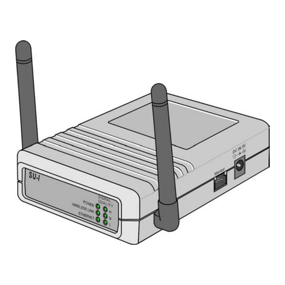
Indoor SU-I and AU-I Units Installing SU-I/I-D and AU-I/I-D Units Connectors and LEDs The unit provides the following interfaces: Figure 3-1: SU-I Rear Panel ! An Ethernet connector (marked ETH) for connecting the unit to the network. See Table 3-1‚ page 3-3 for information on the required type of Ethernet cable. - Page 88 BreezeACCESS Version 4.5 Installation Figure 3-3: SU-I Front Panel Table 3-2: SU-I LEDs Name Description Functionality POWER Power supply On – After successful power up Off – Power off WIRELESS LINK Wireless Link Blinking – Receiving packets from the wireless link Activity Off –...
- Page 89 Indoor SU-I and AU-I Units Figure 3-4:: AU-I Front Panel Table 3-3: AU-I LEDs Name Description Functionality POWER Power supply On – After successful power up Off – Power off WIRELESS LINK Wireless Link Blinking – Receiving packets from the wireless link Activity Off –...
-
Page 90: Wall Mounting The Unit
BreezeACCESS Version 4.5 Installation 3-10 Wall Mounting the Unit Use the supplied brackets for wall mounting to install the unit on a wall or a ceiling. 1. Turn the unit so the rear panel is facing you. 2. Unscrew the two screws located at the antennas end of the unit (the top screws). -
Page 91: Connecting Antenna(S) To The Units
Indoor SU-I and AU-I Units 3-11 Connecting Antenna(s) to the Units For installation convenience, a torque key is included with all BreezeACCESS SU-ID and AU-ID units. WARNING: The use of improper tools for tightening antenna connection cables to BreezeACCESS units may result in damage to the cable connectors. Use the included torque key to tighten the cable(s) to the connector(s) on the side of the unit. - Page 92 BreezeACCESS Version 4.5 Installation 3-12 1. Plug the output jack of the power transformer into the DC input jack (marked DC IN 5V) located on the side of the unit. 2. Connect the power transformer to a power outlet - 110/ 220VAC. 3.
- Page 93 BreezeACCESS II SW Version 4.5 Revision 1.0 System Manual Book 3: Commissioning...
- Page 95 Chapter 1 Setting Basic Parameters About This Chapter This chapter explains how to configure the basic parameters of the BreezeACCESS system and includes the following section: Accessing the Monitor Program‚ page 1-2, explains how to accessyour BreezeACCESS units for configuration. Configuring Basic Parameters in Access and Subscriber Units‚...
-
Page 96: Accessing The Monitor Program
BreezeACCESS Version 4.5 Commissioning Accessing the Monitor Program Accessing the Monitor Program using the RS 232 MON Connector 1. Use the monitor cable to connect the MON connector of the unit to the COM port of your ASCII ANSI terminal or PC. The COM port connector on the monitor cable is a 9-pin D-type plug. -
Page 97: Accessing The Monitor Program Using Telnet
Setting Basic Parameters BreezeACCESS/AU-BS Official Release Version – 4.0.40 Release Date: Thu Dec 20 20:21:36 2001 Main Menu ===================== 1 – Info Screens 2 – Unit Control 3 – Basic Configuration 4 – Site Survey 5 – Advanced Configuration X – Exit >>>... -
Page 98: Operating The Monitor Program
BreezeACCESS Version 4.5 Commissioning Table 1-2: Required Type of Ethernet Cable Connection to a Connection to a Unit Type All SU-R Units and Subscriber Units that support a Straight single Ethernet device (SU-1D, SU-1D1V) Subscriber Units (excluding SU-R Units) that Crossed Straight support multiple Ethernet devices... -
Page 99: Configuring Basic Parameters In Access And Subscriber Units
19 dBm. In legacy units that were upgraded from firmware version 4.3 or lower, it is mandatory to attach the new IC&FCC HDM ID label to the unit. Note that the HDM label is only available from Alvarion when ordering Firmware 4.5.Upgrade Kit. The maximum output power for compliance with the applicable IC&FCC regulations are listed below. - Page 100 BreezeACCESS Version 4.5 Commissioning Table 1-4: Subscriber and Access Units Basic Parameters Parameter Default Value Comment Scrambling Mode Enhanced Applicable only if HDM Mode is enabled Manual Sequence Definition Applicable only when Srambling Mode is configured to Manual Scrambling Spanning Factor Applicable only for Enhanced Scrambling with 7 or more frequencies...
-
Page 101: Configuring Parameters In Gu-A-Bs Units
Setting Basic Parameters Table 1-4: Subscriber and Access Units Basic Parameters Parameter Default Value Comment Authentication Algorithm Open System In the SU, can be changed to Shared Key only after configuring the WEP Key and the applicable Default Key ID. In the AU at least one WEP key must be configured. - Page 102 BreezeACCESS Version 4.5 Commissioning Parameter Default Value Comment IP Address 10.0.0.1 Subnet Mask 255.0.0.0 Default Gateway Address 0.0.0.0 DHCP Option Disable Number of Hopping According to the Number of Frequencies Hopping Frequencies in the AUs Automatic Recovery Option Disable Not Applicable to “slave” modules.
- Page 103 Chapter 2 Optimizing the Wireless Link About This Chapter This chapter explains how to optimize the performance of the wireless link of BreezeACCESS Subscriber Units and includes the following sections: Configuring the Maximum Data Rate (Subscriber Units)‚ page 2-2, explains how to read the RSSI measurement and to configure the optimum value for the Maximum Data Rate parameter.
-
Page 104: Configuring The Maximum Data Rate (Subscriber Units)
BreezeACCESS Version 4.5 Commissioning Configuring the Maximum Data Rate (Subscriber Units) The BreezeACCESS units transmit at data rates of 3 Mbps, 2 Mbps and 1Mbps. If the quality of the link is not sufficient, it is recommended to decrease the value of the Maximum Data Rate. Note that the higher the data rate, the higher the error rate. -
Page 105: Aligning The Antenna Of The Su-A/E Subscriber Unit
Optimizing the Wireless Link Aligning the Antenna of the SU-A/E Subscriber Unit NOTE: Antenna alignment using the RSSI bar display is possible only after the Access Unit you wish to associate with is operational and the basic parameters in the Subscriber Unit were properly configured. -
Page 106: Configuring The Transmit Power Of The Au-Re
BreezeACCESS Version 4.5 Commissioning Configuring the Transmit Power of the AU-RE The transmitted output power of the AU should be adjusted in the following cases: ! If there is a need to cover a relatively small area and to minimize the interference with the operation of neighboring cells. - Page 107 Optimizing the Wireless Link Table 2-2: Transmit Power Control for FCC Certified Antennas Antenna Transmit Power Control Gain* IF cable: IF cable: IF cable: 35m – LMR240 65m – LMR240 150m – LMR400 25m – LMR200 45m – LMR200 100m – RG213 17m –...
-
Page 108: Positioning The Su-I Or Su-R Subscriber Unit With Omni Antennas For Optimal Operation
BreezeACCESS Version 4.5 Commissioning Positioning the SU-I or SU-R Subscriber Unit with Omni Antennas for Optimal Operation To identify the best location for the unit you can either use the signal quality LED indicators on the front panel of the unit or view the Received Signal Strength Indication (RSSI) on the monitor. -
Page 109: Aligning The External Antenna Of Su-R And Su-I-D Units
Optimizing the Wireless Link Aligning the External Antenna of SU-R and SU-I-D Units For Subscriber Units with directional antenna(s), you can either use the signal quality LED indicators on the front panel of the unit or view the Received Signal Strength Indication (RSSI) on the monitor. In most installations, alignment using the LEDs is sufficient. - Page 110 BreezeACCESS Version 4.5 Commissioning Manual Revision: 1.0...
-
Page 111: Bs-Gu Connectors
Chapter 3 BS-GU Connectors About This Chapter This chapter explains how to connect external devices to the AL IN and AL OUT connectors of the BS-GU module. It also includes a description of the cable connecting the BS-GU to the GPS antenna and of the SYNC IN/SYNC OUT connectors’... -
Page 112: Connecting External Devices To The Bs-Gu Al In And/Or Al Out Connectors
BreezeACCESS Version 4.5 Commissioning Connecting External Devices to the BS-GU AL IN and/or AL OUT Connectors Open-ended cables are available from the company for connecting to the module external alarm inputs through the AL IN connector and/or activating external devices through the AL OUT connector. See the tables that follow for descriptions of the connectors’... -
Page 113: Alarms Out Cable
Connecting External Alarm Devices Alarms Out Cable Table 3-2: Alarms Out Cable 9-pin Micro D-Type Description Color Code AL OUT Connector Relay 1 Common Brown Relay 1 Normally Closed White Relay 2 Common Green Relay 3 Common Relay 3 Normally Closed Black Relay 1 Normally Open Purple... - Page 114 BreezeACCESS Version 4.5 Commissioning NOTE: *Descriptions are with respect to the BS-GU SYNC IN connector side. Figure 3-1 shows a 9-pin Micro D-Type Connector (cable side), and Figure 3-2 shows a 12-pin round connector. 9-pin Micro D-Type connector Figure 3-1: 9-pin Micro D-Type Connector (cable side) 12-pin round connector Figure 3-2: 12-pin Round Connector Manual Revision: 1.0...
-
Page 115: Sync Cable
Connecting External Alarm Devices SYNC Cable Cable Type: EIA RS-422 3X2X25AWG +1X2X24 AWG FTP Shielded cable. Table 3-4: SYNC Cable 9-pin Micro D-Type 9-pin Micro D-Type SYNC OUT Description Color Code SYNC-IN Connector Connector GPS TX+/SYNC D+ Black GPS TX-/SYNC D- Brown 1PPS+/SYNC S+ 1PPS-/SYNC S-... - Page 116 BreezeACCESS Version 4.5 Commissioning Manual Revision: 1.0...
- Page 117 Chapter 4 Verifying Proper Operation About This Chapter This chapter explains how to confirm that the BreezeACCESS system is functioning properly and includes the following sections: Verifying Connectivity ‚ page 4-2 , explains how to ensure that your BreezeACCESS and the equipment connected to them are operating properly.
-
Page 118: Verifying Connectivity
BreezeACCESS Version 4.5 Commissioning Verifying Connectivity Verifying the Ethernet Connection Once you have connected the unit to an Ethernet outlet, verify that the Ethernet Integrity indicator (the yellow LED embedded in the Ethernet connector) is on, indicating that the unit is connected to an Ethernet segment. -
Page 119: Verifying Proper Operation Of The Gu-A-Bs Gps Unit
Verifying Proper Operation Verifying Proper Operation of the GU-A-BS GPS Unit NOTE: It may take up to 10 minutes from the time the GU-RA GPS antenna is powered up until it is fully synchronized with the GPS satellite system. When the unit is operating properly, the PWR and OK green LEDS should be on, indicating that the BS-GU module is supplying power to the GU-RA GPS antenna and that the GPS antenna is functioning properly. -
Page 120: Led Indicators
BreezeACCESS Version 4.5 Commissioning LED Indicators To verify correct operation of the units, view the status of the relevant LED indicators: SU-RA/RE Outdoor Units LEDs Table 4-1: SU-RA/RE Outdoor Units LEDs Name Description Functionality ALARM Alarm On – A problem with the power amplifier or in the locking indication process of any of the synthesizers Off –... -
Page 121: Su-Ni And Au-Ni Indoor Units Leds
Verifying Proper Operation SU-NI and AU-NI Indoor Units LEDs Table 4-3: SU-NI and AU-NI Indoor Units LEDs Name Description Functionality Power supply On – After successful power up, indicating that 12 VDC is supplied to the outdoor unit. Off – Power off or DC/DC converter failure (12 VDC not supplied to the outdoor unit) WLNK Wireless link... -
Page 122: Bs-Au Leds
BreezeACCESS Version 4.5 Commissioning BS-AU LEDs Table 4-6: BS-AU LEDs Name Description Functionality Power supply On – After successful power up, indicating that 12 VDC is 12 VDC supplied to the outdoor unit. Off – Power off or DC/DC converter failure (12 VDC not supplied to the outdoor unit) WLNK Wireless link... -
Page 123: Su-R Leds
Verifying Proper Operation SU-R LEDs Table 4-8: SU-R LEDs Name Description Functionality Power supply On – After successful power up Off – Power off SIGNAL Quality of Very low quality reception or not QUALITY received RF signal synchronized with Access Unit. Low quality reception (usually enabling 1Mbps traffic). -
Page 124: Au-I/Au-I-D Leds
BreezeACCESS Version 4.5 Commissioning AU-I/AU-I-D LEDs Table 4-10: AU-I/AU-I-D LEDs Name Description Functionality POWER Power supply On – After successful power up Off – Power off WIRELESS Wireless Link Blinking – Receiving packets from the wireless link LINK Activity Off – no reception of packets from the wireless link LOAD Number of active No subscribers... - Page 125 BreezeACCESS II SW Version 4.5 Revision 1.0 System Manual Book 4: Operations and Administration...
-
Page 127: Accessing The Monitor Program
Chapter 1 Accessing the Monitor Program About This Chapter This chapter explains how to access the monitor program. It also describes how to use the monitor program to set up, configure, and manage BreezeACCESS Broadband Wireless Access system units. This includes the Subscriber Units (SUs), Access Units (AUs) and GPS and Alarms modules (GUs). -
Page 128: Accessing The Monitor Program Using
The GU-BS GPS and Alarms module does not have an external MON port. It does have an internal MON port that can be used in laboratory conditions (consult Alvarion technical support for further details). It is recommended to use Telnet to access the monitor program of the GU-BS. -
Page 129: Accessing The Monitor Program Using Telnet
Accessing the Monitor Program Accessing the Monitor Program using Telnet 1. Connect a PC to the Ethernet port of the unit. See the table below to determine the type of cable. Configure the PC’s IP parameters to enable connectivity with the unit (the default IP Address is 10.0.0.1). Run the Telnet application. -
Page 130: Operating The Monitor Program
BreezeACCESS Version 4.5 Operations and Administration Screens option is displayed. Users with this access level cannot access the Unit Control, Basic Configuration, Site Survey and Advanced Configuration menus. ! For users with Installer access rights, the first four menu items (Info Screens, Unit Control, Basic Configuration and Site Survey) are displayed. -
Page 131: Menus And Parameters
Chapter 2 Menus and Parameters About This Chapter This chapter describes the BreezeACCESS configuration menus and parameters. It includes the following sections: Main Menu‚ page 2-2. Info Screens Menu‚ page 2-3. Unit Control Menu‚ page 2-6. Basic Configuration Menu‚ page 2-14. Site Survey Menu‚... -
Page 132: Main Menu
BreezeACCESS Version 4.5 Operations and Administration Main Menu From the Main Menu you can access the following menus, depending on your access level: ! Info Screens – Provides read-only display of current parameter values. Available at all access levels. ! Unit Control – Enables access to general operations such as resetting the unit, loading the default parameters, changing passwords and switching between software versions. -
Page 133: Info Screens Menu
Menus and Parameters Info Screens Menu BreezeACCESS/AU-BS Official Release Version – 4.5.5 Release Date: Wed Jan 07 13:30:52 2004 Info Screens ==================== 1 – Show Unit Status 2 – Show Basic Parameters 3 – Show Advanced Parameters S – Show All Parameters >>>... - Page 134 BreezeACCESS Version 4.5 Operations and Administration " Version After Reset – Displays the software version that will be used after the next reset. ! Console Speed – Displays the speed defined in the unit for the connected terminal, used for running the terminal emulation program.
-
Page 135: Show Basic Parameters
Menus and Parameters The following parameters appear for GPS Modules only: ! Unit Status – Indicates the status of the GPS antenna. Either one of the following messages may be displayed: " UTC is available; date..; time..: This message indicates that the GPS antenna has synchronized with the satellite system and that the BS-GU is functioning properly. -
Page 136: Unit Control Menu
Set Complete Factory Defaults – Available only with Administrator access rights. Resets the unit to the set of Alvarion’s standard default values. These are the default values as defined in this manual for each of the parameters. After the next reset all parameters will revert to their Factory Defaults value, except for the parameters that are marked in the “Complete”... - Page 137 Menus and Parameters Table 2-1: Parameters not changed after Set Complete/Partial Factory Defaults Partial – Partial - Parameter Complete Admin Installer Unit Control Parameters Passwords ÷ ÷ ÷ Event Log Policy ÷ Auto Configuration Option ÷ IP Parameters IP Address ÷...
- Page 138 BreezeACCESS Version 4.5 Operations and Administration (Continued) Partial – Partial - Parameter Complete Admin Installer VLAN Relaying Support ÷ ÷ Relaying VLAN IDs ÷ ÷ VLAN Priority – Data ÷ ÷ VLAN Priority – Management ÷ ÷ VLAN Priority – Voice ÷...
- Page 139 Menus and Parameters Set Complete Operator Defaults – Available only with Administrator access rights. Set the unit to its’ Operator Defaults configuration. After the next reset, all parameters will revert to their Operator Defaults values, except for the parameters that are marked in the “Complete” column of Table 2-1‚...
- Page 140 BreezeACCESS Version 4.5 Operations and Administration 2-10 ! Change Password – Changes the password(s). A user with Installer access rights can change the passwords for Read Only and Installer levels. A user with Administrator access rights can change the passwords of all levels. Valid values: A string of up to 8 printable ASCII characters.
- Page 141 Menus and Parameters 2-11 for storing it. Events are classified according to their severity level: Trace (lowest severity), Message, Warning, Error or Fatal (highest severity). The severity at which events are saved in the Event Log is configurable. Events from the configured severity and higher are saved and may be displayed upon request.
- Page 142 BreezeACCESS Version 4.5 Operations and Administration 2-12 The address of the TFTP server and the proper name of the configuration file must be configured in the DHCP server: The Server Address should be specified in the ‘sname’ field of the DHCP header. The code for this option is 66, and the minimum length is 1.
- Page 143 Menus and Parameters 2-13 ! Remote Set IP (AU only) - A sub-menu that enables setting the IP parameters of an SU whose IP parameters are not known via the AU associated with it. The feature is based on generation of a Set IP broadcast by the AU, using the SU's MAC Address, its Read/Write community and, when applicable, its VLAN Management ID.
-
Page 144: Basic Configuration Menu
BreezeACCESS Version 4.5 Operations and Administration 2-14 Basic Configuration Menu The Basic Configuration menu includes all the parameters that are necessary for the initial installation and operation of the unit. Once the unit is properly installed and operational, other parameters can be configured either locally using the monitor program or remotely using Telnet, SNMP management or TFTP for loading to the unit a pre-prepared configuration file. -
Page 145: Vlan Parameters
Menus and Parameters 2-15 VLAN Parameters ! VLAN ID – Management (AU and SU without voice support) (see page 2-73) ! VLAN ID – Voice & Management (SU with voice support) (see page 2-74) ! VLAN Link Type (see page 2-75) Security Parameters ! Authentication Algorithm... -
Page 146: Site Survey Menu
BreezeACCESS Version 4.5 Operations and Administration 2-16 Site Survey Menu The Site Survey menu provides various tests and counters for verifying the quality of the wireless link and the proper operation of the unit. These tests can be used to help determine where to position the units for optimal coverage, to align antennas and to assist in troubleshooting. - Page 147 Menus and Parameters 2-17 Wireless Link Counters The unit transmits data frames received from the Ethernet port, as well as self-generated control and wireless management frames, to the wireless media. After transmission of a unicast frame, the unit waits for an acknowledgement (ACK) message from the receiving unit.
- Page 148 BreezeACCESS Version 4.5 Operations and Administration 2-18 If the ACSE Option is enabled, then in addition to the total count, there are also separate counters for total number of data frames and voice (RTP) frames. The voice frames count includes fax frames. This is true also for Subscriber Units that do not support voice in cells where the ACSE Option in the AU is enabled.
-
Page 149: Voice Statistics(Su With Voice Support Only)
Menus and Parameters 2-19 ! Bad fragments received – Displays the number of frames received from the wireless media with errors (CRC errors). ! Duplicate frames discarded – Displays the number of frames discarded due to receiving multiple copies. If an acknowledge message was not received by the originating unit, the same data frame can be properly received twice (or more). -
Page 150: Ping Test (Au, Su And Gu)
BreezeACCESS Version 4.5 Operations and Administration 2-20 Hopping Statistics The number of the information row, assigned automatically and sequentially by the program. Freq The hopping frequency, according to the hopping sequence. The accumulated number of frames received at the specified frequency since last reset. -
Page 151: Continuous Link Quality Display
Menus and Parameters 2-21 ! Start Sending – Starts transmission of ping frames. ! Stop Sending – Stops the transmission of ping frames. The test will end automatically once the number of pings that were sent has reached the value specified in the No. of Pings parameter (described above). - Page 152 The MAC address of the AU (appears twice as it is learned from both the Ethernet and the wireless ports) Alvarion’s Multicast address (01:20:D6:00:00:01, also twice). The system handles this address as a Broadcast address. The Ethernet Broadcast address (FF-FF-FF-FF-FF-FF)
- Page 153 Menus and Parameters 2-23 " The SW version of the SU. Table 2-2: Association Process (Active Scanning) Message Direction Status in AU SU Scanning* SU → AU Probe Request (including ESSID) - Scanning AU → SU Probe Response (only if correct ESSID in Probe Request) SU Synchronized SU →...
-
Page 154: Per-Rate Counters (Au And Su)
BreezeACCESS Version 4.5 Operations and Administration 2-24 Per-rate Counters (AU and SU) Resets or displays the per-rate counters. The per-rate counters display the number of frames (excluding retransmissions) transmitted since the last reset at each of the rates (1 Mbps, 2 Mbps, 3 Mbps) and the total number of frames that were retransmitted at each of the rates. -
Page 155: Au Alarms (If-Based Au Only)
Menus and Parameters 2-25 AU Alarms (IF-based AU Only) The AU Alarms feature enables to identify and alert upon the detection of a potential problem in the outdoor unit of the AU, or another problem that causes significant degradation in the performance of the wireless link. - Page 156 BreezeACCESS Version 4.5 Operations and Administration 2-26 In addition, the Average Rate is also calculated for each of the above traffic statistics rates, using the formula Ra(t)=[Rc*1 +Ra(t-1)*5]/6, where: Rc - Current Rate Ra(t) - The new value of the Average Rate for the applicable rate. Ra(t-1) - the previous Average Rate of the applicable rate.
- Page 157 Menus and Parameters 2-27 Based on the RSSI information responses from the SUs, the AU performs a calculation of the SU Rx Power Average Delta, defined as the average difference for all SUs between the last RSSI at the SU and the previous (one before last) RSSI.
- Page 158 BreezeACCESS Version 4.5 Operations and Administration 2-28 Association Tests If the AU was reset 3 times because no SU became associated with it, a No Associations critical alarm will be generated, provided that previously the AU was associated with at least Minimum Number Of SUs.
- Page 159 Menus and Parameters 2-29 All Associations Lost Alarm Severity: Major On Conditions: No response from any SU to the last 3 polling messages, and prior to that the average number of responding SUs was not lower than the Minimum Number Of SUs. Off Conditions: a.
- Page 160 BreezeACCESS Version 4.5 Operations and Administration 2-30 High Retransmissions Rate Alarm Severity: Minor, Major On Conditions: Minor Severity Alarm: a. The Retransmissions Current Rate exceeds the Retransmissions Minor Alarm Threshold, and is higher than the Retransmissions Average Rate by at least Retransmissions Minor Alarm Minimum Delta, -OR- b.
- Page 161 Menus and Parameters 2-31 High Dropped Frames Rate Alarm Minor, Major Severity: On Conditions: Minor Severity Alarm: a. The Dropped Frames Current Rate exceeds the Dropped Frames Minor Alarm Threshold, and is higher than the Dropped Frames Average Rate by at least Dropped Frames Minor Alarm Minimum Delta, -OR- b.
- Page 162 BreezeACCESS Version 4.5 Operations and Administration 2-32 High CRC Error Rate Alarm Severity: Minor, Major On Conditions: Minor Severity Alarm: a. The CRC Error Current Rate exceeds the CRC Error Minor Alarm Threshold, and is higher than the CRC Error Average Rate by at least CRC Error Minor Alarm Minimum Delta, -OR- b.
- Page 163 Menus and Parameters 2-33 High Duplicate Frames Rate Alarm Severity: Minor, Major On Conditions: Minor Severity Alarm: a. The Duplicate Frames Current Rate exceeds the Duplicate Frames Minor Alarm Threshold, and is higher than the Duplicate Frames Average Rate by at least Duplicate Frames Minor Alarm Minimum Delta, -OR- b.
- Page 164 BreezeACCESS Version 4.5 Operations and Administration 2-34 The AU Alarms Menu The AU Alarms menu enables to configure relevant parameters and to view current statistics. The AU Alarms menu is available only with Administrator access rights, except for Show All AU Alarms Parameters and Data that is also available with Installer access rights.
- Page 165 Menus and Parameters 2-35 The default parameters for these alarms is as follows: Parameter Default (%) Retransmission Minor Alarm Minimum Delta Retransmission Minor Alarm Threshold Retransmission Major Alarm Threshold Dropped Frames Minor Alarm Minimum Delta Dropped Frames Minor Alarm Threshold Dropped Frames Major Alarm Threshold CRC Error Minor Alarm Minimum Delta CRC Error Minor Alarm Threshold...
- Page 166 BreezeACCESS Version 4.5 Operations and Administration 2-36 Default value: 15 (dB). " Show AU Rx Power Test Parameters and Data - Displays the value of the AU Rx Power Decrease Threshold and the current AU Rx Power Average Delta. ! Responding SUs - a sub menu that includes the following options: "...
-
Page 167: Advanced Configuration Menu
Menus and Parameters 2-37 Advanced Configuration Menu The Advanced Configuration menu provides access to all the parameters, including the parameters that are available through the Basic Configuration menu. The Advanced Configuration menu provides access to the following menus: ! IP Parameters (AU, SU and GU) (see page 2-37) ! Air Interface Parameters (AU and SU) -
Page 168: Air Interface Parameters (Au And Su)
BreezeACCESS Version 4.5 Operations and Administration 2-38 ! DHCP Client " DHCP Options – Displays the current status of the DHCP (Dynamic Host Configuration Protocol) support, and allows selecting a new operation mode. The available options are: Disable – Use manual procedure for configuring the IP parameters. - Page 169 Menus and Parameters 2-39 Modulation (HDM) mode. The HDM mode enables flexible selection of the frequencies and supports auto learning of the parameters in the SUs. NOTE: HDM Mode is not certified for use by SU-R units. Using Hopping Set and Hopping Sequence (Shift) ! Hopping Sequence (Shift) –...
- Page 170 BreezeACCESS Version 4.5 Operations and Administration 2-40 Table 2-3: Country Standards Supported by BreezeACCESS II Hopping Hopping Country Frequency Number of Sequences per Sync Standard Range [MHz] Channels Hopping Set Support Australia 2402 to 2461 Canada 2452 to 2481 Europe ETSI...
- Page 171 Menus and Parameters 2-41 the basic sequence and the number of hopping frequencies also define the hopping shift mechanism for generating different actual hopping sequences. 3. If two or more non-synchronized AUs are co-located and Enhanced Scrambling is used for generating the basic sequence, configure the Spanning Factor parameter to define a different hopping sequence for each AU in order to minimize interference between adjacent AUs.
- Page 172 BreezeACCESS Version 4.5 Operations and Administration 2-42 ! Scrambling Definitions - The Scrambling Definitions menu enables defining the method of organizing the selected frequencies to form the actual hopping sequence to be used. Proper organization of the hopping sequence is essential to guarantee minimal cross interference between several neighboring cells that use the same sequence with different Hopping Sequence (Shift) values.
- Page 173 Menus and Parameters 2-43 The first channel in the basic scrambled sequence is frequency 1. Frequency 1 (index=1) is the lowest frequency in the list of frequencies to be used, frequency 2 is the next frequency and so on.) The index of each of the other channels is calculated by adding the Spanning Factor to the index of the previous channel.
- Page 174 BreezeACCESS Version 4.5 Operations and Administration 2-44 Valid values: 1 to Number of Hopping Frequencies minus 1, provided it meets the GCD requirement as described above. It is not recommended to use spanning factors of 1 and N-1, as they result in hopping on consecutive channel (assuming that the available channels are consecutive).
- Page 175 Menus and Parameters 2-45 Spanning Channels Hopping Sequences Factor 1, 2, 3, 4, 5, 6, 7 1, 3, 5, 7, 2, 4, 6 1, 4, 7, 3, 6, 2, 5 1, 5, 2, 6, 3, 7, 4 1, 6, 4, 2, 7, 5, 3 1, 7, 6, 5, 4, 3, 2 1, 2, 3, 4, 5, 6, 7, 8 1, 4, 7, 2, 5, 8, 3, 6...
- Page 176 BreezeACCESS Version 4.5 Operations and Administration 2-46 Spanning Channels Hopping Sequences Factor 1, 2, 3, 4, 5, 6, 7, 8, 9, 10, 11, 12, 13, 14 1, 4, 7, 10, 13, 2, 5, 8, 11, 14, 3, 6, 9, 12 1, 6, 11, 2, 7, 12, 3, 8, 13, 4, 9, 14, 5, 10 1, 10, 5, 14, 9, 4, 13, 8, 3, 12, 7, 2, 11, 6 1, 12, 9, 6, 3, 14, 11, 8, 5, 2, 13, 10, 7, 4...
- Page 177 Menus and Parameters 2-47 Spanning Channels Hopping Sequences Factor 1, 2, 3, 4, 5, 6, 7, 8, 9, 10, 11, 12, 13, 14, 15, 16, 17, 18, 19 1, 3, 5, 7, 9, 11, 13, 15, 17, 19, 2, 4, 6, 8, 10, 12, 14, 16, 18 1, 4, 7, 10, 13, 16, 19, 3, 6, 9, 12, 15, 18, 2, 5, 8, 11, 14, 17 1, 5, 9, 13, 17, 2, 6, 10, 14, 18, 3, 7, 11, 15, 19, 4, 8, 12, 16 1, 6, 11, 16, 2, 7, 12, 17, 3, 8, 13, 18, 4, 9, 14, 19, 5, 10, 15...
- Page 178 BreezeACCESS Version 4.5 Operations and Administration 2-48 Spanning Channels Hopping Sequences Factor 1, 2, 3, 4, 5, 6, 7, 8, 9, 10, 11, 12, 13, 14, 15, 16, 17, 18, 19, 20, 21, 22, 23 1, 3, 5, 7, 9, 11, 13, 15, 17, 19, 21, 23, 2, 4, 6, 8, 10, 12, 14, 16, 18, 20, 22 1, 4, 7, 10, 13, 16, 19, 22, 2, 5, 8, 11, 14, 17, 20, 23, 3, 6, 9, 12, 15, 18, 21 1, 5, 9, 13, 17, 21, 2, 6, 10, 14, 18, 22, 3, 7, 11, 15, 19, 23, 4, 8, 12, 16, 20 1, 6, 11, 16, 21, 3, 8, 13, 18, 23, 5, 10, 15, 20, 2, 7, 12, 17, 22, 4, 9, 14, 19...
- Page 179 Menus and Parameters 2-49 Spanning Channels Hopping Sequences Factor 1, 2, 3, 4, 5, 6, 7, 8, 9, 10, 11, 12, 13, 14, 15, 16, 17, 18, 19, 20, 21, 22, 23, 24, 25 1, 3, 5, 7, 9, 11, 13, 15, 17, 19, 21, 23, 25, 2, 4, 6, 8, 10, 12, 14, 16, 18, 20, 22, 24 1, 4, 7, 10, 13, 16, 19, 22, 25, 3, 6, 9, 12, 15, 18, 21, 24, 2, 5, 8, 11, 14, 17, 20, 23...
- Page 180 BreezeACCESS Version 4.5 Operations and Administration 2-50 Max. Hopping Sequence (Shift) (channels) = Number of hopping frequencies-1. The actual hopping sequences depend on the method used for defining the basic hopping sequence: Standard Scrambling, Enhanced Scrambling or Manual Sequence Definition. In Enhanced Scrambling mode it depends also on the number of frequencies.
- Page 181 Menus and Parameters 2-51 2414 2417 2412 2415 2418 2413 2416 2411 2415 2418 2413 2416 2411 2414 2417 2412 2416 2411 2414 2417 2412 2415 2418 2413 2417 2412 2415 2418 2413 2416 2411 2414 2418 2413 2416 2411 2414 2417 2412...
- Page 182 BreezeACCESS Version 4.5 Operations and Administration 2-52 Table 2-7: Hopping Sequence (Shift) Implementation, Standard Scrambling (N=6) Hopping Sequence (Shift)) Actual Sequence Indexes 0 (basic sequence) 1, 3, 5, 2, 6, 4 3, 5, 2, 6, 4, 1 5, 2, 6, 4, 1, 3 2, 6, 4, 1, 3, 5 6, 4, 1, 3, 5, 2 4, 1, 3, 5, 2, 6...
- Page 183 Menus and Parameters 2-53 (i) is element number in the basic hopping sequence (s=0). For example, in the basic sequence with N=6: (1) =1 (2)=3 (3)=5 (4)=2 (5)=6 (6)=4 For a shift of 3, the actual sequence is: (1) =P [(1+3-1)mod6+1]=P (4)=2 (2) =P...
- Page 184 BreezeACCESS Version 4.5 Operations and Administration 2-54 Hopping Sequence (Shift) Range and Default Value The permitted range for the Hopping Sequence (Shift) parameter is from 0 to N-1, where N is the number of hopping frequencies. The default is 0 Hopping Sync (BS-AU only) –Displays the current Hopping Sync status of the unit and allows defining a new status.
- Page 185 Menus and Parameters 2-55 The default value is ESSID1. ! Operator ESSID Parameters (AU only) – The Operator ESSID is a secondary ESSID that can only be configured in the AU. The Operator ESSID can be used to enhance flexibility and reduce configuration effort when adding new Subscriber Units to operational installations in which different ESSIDs were configured for different sectors that actually belong to the same network.
- Page 186 BreezeACCESS Version 4.5 Operations and Administration 2-56 AUs it can communicate with. At the end of the scanning period, the SU reaches a Best AU decision according to the information gathered. The AU with the highest quality mark is selected as the Best AU, and the SU will immediately try to associate with it.
- Page 187 Menus and Parameters 2-57 NOTE: When Best AU support is enabled, it is recommended to use Active Scanning. If passive scanning is used, the SU may not hear the best AU (or the preferred AU). The higher the number of hopping channels, the higher the probability that the SU will not hear the best (or preferred) AU when passive scanning is used.
- Page 188 BreezeACCESS Version 4.5 Operations and Administration 2-58 Power Control Parameters The power control parameters enable to optimize the performance of the system through controlling the transmitted power level of BreezeACCESS units. The transmitted power level of the unit should be decreased from the maximum level that is supported by the unit in the following cases: ! In a Subscriber Unit that is relatively close to the Access Unit, in...
- Page 189 Menus and Parameters 2-59 ! Transmit Power Control (IF-based units only – SU-A/E, AU-BS and AU-NI) – Controls the relative gain of the Tx power circuits. A value of 15 represents the highest transmit power level, which is the maximum level supported by the specific unit. A lower value represents a lower transmit power level.
- Page 190 18+/- 5 16+/- 5 11+/- 5 6+/- 5 New BreezeACCESS II AU-RA/RE-HP outdoor units, have an output power control mechanism that is different from previous units. The main differences are: a. Higher Transmit Power Control dynamic range b. The output power is not dependent on the attenuation of the IF cable.
- Page 191 Menus and Parameters 2-61 Table 2-10: Transmit Power Output in New AU Outdoor Units Transmit Power Control Outdoor Unit Power (dBm) 26.7 24.5 20.8 19.2 17.2 15.5 12.1 11.3 -0.2 ! Power Level - Applicable to all SU-R units and to SU-I/AU-I units with HW version C or lower.
- Page 192 BreezeACCESS Version 4.5 Operations and Administration 2-62 ! Transmit Level - Applicable to SU-I/AU-I units with HW version D or higher. Sets the transmit power level at the antenna port(s). Valid values: 0 – 21 (dBm) Default value: 17 (dBm) NOTE: For compliance with FCC requirements, the Transmit Level parameter in SU-I/I-D and AU-I/I-D units with HW revision D or higher that operate in HDM...
- Page 193 Menus and Parameters 2-63 Default value: 120 seconds. " ATPC Power Level Step - The step size in percentages of maximum number of available levels that the SU will use when receiving an ATPC Power-Up/Power-Down message. The formula for calculating the step size is: Step=max{1, [ATPC Step*(No.
- Page 194 BreezeACCESS Version 4.5 Operations and Administration 2-64 range/speed trade-off), you may decide to limit the use of higher rates. If the quality of the link is not good enough, it is recommended to decrease the value of this parameter (the higher the data rate, the higher the error rate).
- Page 195 Menus and Parameters 2-65 decrease the overall performance and achievable network throughput. It should be increased only to support ranges of over 10 km. If the range was increased for one SU, it must be increased to the same value for the AU. Valid values are: Low (up to 10 km), Medium (up to 20 km) and High (more than 20 km).
- Page 196 BreezeACCESS Version 4.5 Operations and Administration 2-66 ACSE voice calls will be terminated (no slot will be allocated for the call). The allowed range for the Call Aging Time parameter is 1 (no aging) or 2-50,000 seconds. It is recommended to configure a call aging time of at least 1200 (20 minutes).
- Page 197 Menus and Parameters 2-67 receive circuit is equivalent to reducing the level of the received signal (including both signal and noise) by 2 dB when selecting 10 dB attenuation and 12 dB when selecting 25 dB attenuation. The default is 0 dB. ! ACSE Parameters –...
- Page 198 BreezeACCESS Version 4.5 Operations and Administration 2-68 including units that do not support voice, since they are also affected by the use of the ACSE protocol. Valid values are from 0 (no retransmissions) to 100. The default value is 6. "...
- Page 199 Menus and Parameters 2-69 ! Wireless Trap Threshold - Enables to define the threshold for the wireless quality traps: The brzaccAUWirelessQualityTRAP or the brzaccSUWirelessQualityTRAP indicate that the quality of the wireless link has gone below or above the specified threshold. For AU the threshold is in percents of retransmissions.
-
Page 200: Network Management Parameters (Au, Su And Gu)
BreezeACCESS Version 4.5 Operations and Administration 2-70 " Max Number of Association/Authentication Timeouts - A timer is started each time the SU reboots. If the timer expires before the SU succeeded to associate with an AU, the Number of Associations/Authentication Timeout counter is incremented by 1 and the timer is restarted. - Page 201 Menus and Parameters 2-71 " Disable – No IP address based filtering " Activate Management IP Filter On Ethernet Port – Applicable only if the Access to Network Management parameter is configured to either From Ethernet Only or From Both Ethernet &...
- Page 202 BreezeACCESS Version 4.5 Operations and Administration 2-72 ! Enable Traps Sending - enables sending of SNMP Traps. The Traps that will be sent can be defined by the Per Trap Control menu. The addresses to which these traps will be sent and the SNMP Communities associated with these Traps are defined by the SNMP Traps IP Destination and the SNMP Traps Community options.
-
Page 203: Bridge Parameters (Au, Su And Gu)
Menus and Parameters 2-73 The default of all three SNMP Traps IP Destinations is 0.0.0.0. " SNMP Traps Community – Defines a new community string for each of the 3 SNMP Trap IP Destination entries. Valid strings: Up to 14 ASCII characters, case sensitive. The default for all 3 entries is public (read-only). - Page 204 BreezeACCESS Version 4.5 Operations and Administration 2-74 Frames received from the Wireless link port: ! Only tagged frames with VLAN ID (VID) value equal to the VLAN ID Data defined in the unit are forwarded to the Ethernet port. ! The tag headers are removed from the data frames received from the wireless link prior to transmitting them on the Ethernet port.
- Page 205 Menus and Parameters 2-75 Table 2-13: Management Port Functionality – AU, SU without Voice Support and GU Action Management Port – internal (SU) Receive from Ethernet Tagged frames, matching VID-M Untagged frames when VID-M=65535 Receive from Wireless Tagged frames, matching VID-M (AU and SU) Untagged frames when VID-M=65535 Transmit...
- Page 206 BreezeACCESS Version 4.5 Operations and Administration 2-76 value of the VLAN ID – Voice & Management parameter. The table is valid for all link types. See VLAN Link type – Access Link and Trunk Link for some restrictions when configuring this parameter. Table 2-14: Management and Voice Ports Functionality –...
- Page 207 Menus and Parameters 2-77 Trunk Link – Transfers only tagged frames, because all devices connected to it are VLAN-aware: Only tagged data frames received on Ethernet or wireless link ports are forwarded. WARNING: It is not recommended to configure a unit as a Trunk Link with VLAN ID - Management (or VLAN ID - Voice &...
- Page 208 BreezeACCESS Version 4.5 Operations and Administration 2-78 or VLAN-unaware. This is equivalent to defining no VLAN support, as the unit is transparent to VLAN. The following table summarizes the functionality of the data port for a Hybrid link: Table 2-17: VLAN Data Port Functionality Summary– Hybrid Link Data Port Action (SU and AU)
- Page 209 Menus and Parameters 2-79 Show VLAN ID Forwarding List – Displays the values of the VLAN IDs that are included in the VLAN Forwarding List. NOTE: If the VLAN ID Forwarding List is empty and the VLAN Forwarding Support is enabled, then all data frames will be discarded.
- Page 210 BreezeACCESS Version 4.5 Operations and Administration 2-80 BreezeACCESS Subscriber and Access Units support Layer 2 traffic prioritization based on the IEEE 802.1p standard. The priority field in the 802.1Q header tag can have a value in the range 0-7. This value determines the relative priority of the packet.
- Page 211 Menus and Parameters 2-81 parameter only impacts the way that other VLAN-aware devices will handle the packet. Valid values are 0-7. The default value is 4 for SU units with voice support and 0 for all other units. VLAN Priority – Voice (SU with voice support only) – Applicable for all link types.
-
Page 212: Ethernet Broadcast Filtering
BreezeACCESS Version 4.5 Operations and Administration 2-82 supports quality of service based on IPv4 ToS, the value of this parameter should be configured according to the definitions of the router/gateway in order to take advantage of the QoS feature and to ensure that voice packets will be handled accordingly. Valid values are 0-255. - Page 213 Menus and Parameters 2-83 The Ethernet Broadcasting Filtering menu allows viewing and setting the following parameters: ! Filter Options (SU only) – Defines the Ethernet broadcast filtering functionality of the unit. The following options are available: " Disable: No Ethernet broadcast filtering "...
- Page 214 BreezeACCESS Version 4.5 Operations and Administration 2-84 Available selections are: " Disable– ARP Broadcast messages are filtered or transmitted according to the general filtering criteria set by the Filter Options parameter. " Enable– ARP Broadcast messages are transmitted regardless of the selected value of the Filter Options parameter.
- Page 215 Menus and Parameters 2-85 transmitted by the AU back to the wireless link devices, as well as to the wired LAN. If disabled, these packets are sent only to the local wired LAN and are not sent back to the wireless link. Disable Broadcast Relaying if you are sure that all broadcast messages from the wireless link will be destined to the wired LAN.
-
Page 216: Performance Parameters (Au And Su)
BreezeACCESS Version 4.5 Operations and Administration 2-86 Performance Parameters (AU and The Performance Parameters menu includes the following parameters: ! RTS Threshold – Defines the minimal frame size to require RTS/CTS (Request To Send/Clear To Send) handshake. Frames with a size below the RTS Threshold value are transmitted directly to the wireless link without being preceded with RTS frames. - Page 217 Menus and Parameters 2-87 ! Minimum Contention Window – The BreezeACCESS system uses a special mechanism based on detecting the presence of a carrier signal (Carrier Sense Multiple Access-CSMA) and analyzing the information contained in the transmissions of the AU to estimate the activity of other SUs served by the same AU.
- Page 218 BreezeACCESS Version 4.5 Operations and Administration 2-88 number of successful windows at a certain rate required to reach a decision to increase the rate depends on previous rate of unsuccessful windows at the higher rate. The higher the rate of previous unsuccessful windows at a specific rate, the higher is the number of required consecutive successful windows at the lower rate prior to increasing the rate...
- Page 219 Menus and Parameters 2-89 ! Interference Avoidance Parameters: These parameters enable to define the interference avoidance algorithm. The algorithm is designed to minimize the probability of the modem identifying interference as a possible desired signal. Such an occurrence should be avoided, as locking on the interfering signal may disable the modem from timely identifying the appearance of a desired signal.
- Page 220 BreezeACCESS Version 4.5 Operations and Administration 2-90 " Noise Floor: Enables the user to set the equivalent noise level that is affected by the thermal noise and the average interference level. Available values: -115 to –50 (dBm). Default values: IF-based units: -112(dBm) SU-R: -101(dBm) SU-I/AU-I: -97 (dBm) "...
-
Page 221: Service Parameters (Au And Su)
Menus and Parameters 2-91 algorithm is enabled, then the Runtime Noise Floor is the higher of the following two values: a. The configured Noise Floor. b. Calculated Noise Floor: Average RSSI[dBm] – Delta - Fading Factor – 2dB. Where Delta is a hard coded value that may differ among product types. - Page 222 BreezeACCESS Version 4.5 Operations and Administration 2-92 Disable (No filtering). IP Only (only IP Protocol packets pass). User Defined Addresses Only (only IP messages from/to IP addresses included in the User Filter Addresses list pass). PPPoE Protocol Only (only PPPoE frames pass - Ethernet type 0x8863 and 0x8864).
- Page 223 Menus and Parameters 2-93 Under normal conditions, the actual Information Rate (IR) will be between the applicable CIR and MIR values: IR=CIR+K(MIR-CIR), where K is between 0 to 1 and is determined dynamically by the AU according to overall demand in the cell and the prevailing conditions that may influence the performance of the wireless link.
- Page 224 BreezeACCESS Version 4.5 Operations and Administration 2-94 Valid values are from 32 to 2200Kbps. The default value is 128Kbps. " CIR: AU to SU (SU only) – Sets the Committed Information Rate of the down-link from the AU to the SU. The CIR value cannot be higher than the corresponding MIR value.
-
Page 225: Radius Parameters Menu (Subscriber Units Only)
Menus and Parameters 2-95 Degradation Limit. Higher demand can be expected in cases of significant over subscription and/or in deployments where a high number of subscribers are in locations that do not enable proper communication with the AU at the highest data rate. Valid values: 0 –... - Page 226 BreezeACCESS Version 4.5 Operations and Administration 2-96 Transactions between the client and RADIUS server are authenticated through the use of a shared secret, which is never sent over the network. In addition, any user passwords are sent encrypted between the client and RADIUS server, using a method based on the RSA Message Digest Algorithm MD5.
- Page 227 Menus and Parameters 2-97 ! Shared Secret – To define the key that will be used for encrypting the User Password for increased security. The algorithm used for encrypting the User Password is MD5. Valid values: A string of up to 20 printable ASCII characters, case sensitive.
- Page 228 BreezeACCESS Version 4.5 Operations and Administration 2-98 server. The Accounting Parameters menu includes the following parameters: ! Accounting Option - To enable or disable the accounting records transmission feature. When this option is enabled and the RADIUS Server Accounting IP Address is configured to an address other than 0.0.0.0., the SU enables the RADIUS accounting client.
-
Page 229: Security Parameters (Au And Su)
Menus and Parameters 2-99 Table 2-19: Ethernet Vendor Specific Record Structure (Vendor Specific ID is 710) Field Format Description Traffic Type 1 hexadecimal digit Data (0)/Management (1)/Voice (2). VLAN ID 3 hexadecimal digits VLAN ID. Layer 3 4 hexadecimal digits Third layer protocol type (IP, ARP). - Page 230 BreezeACCESS Version 4.5 Operations and Administration 2-100 " Open System: An SU configured to Open System can be authenticated only by an AU that is also configured to Open System. The WEP algorithm is not used. " Shared Key: Authentication enabled. The authentication messages are encrypted.
-
Page 231: Telephony Parameters (Subscriber Units With Voice Support Only)
Menus and Parameters 2-101 The default for all 4 keys is a string of 10 zeros (no key). NOTE: It is recommended to change the WEP Keys periodically, to enhance system security. Wireless Media Security Wireless media security is provided by preventing the ability to perform data sniffing on the air. - Page 232 BreezeACCESS Version 4.5 Operations and Administration 2-102 Voice Parameters The parameters in the Voice Parameters menu include the following options: ! Volume – Sets the gain of the voice signal to the earphone. Available range is 0 dB to -20 dB in 1 dB steps. The default value is -3 dB.
- Page 233 Menus and Parameters 2-103 6 if ACSE Option is enabled. (covers all G729 codecs, including G729Annex A, G729wAnnexB and G729AnnexAwAnnexB) " G711u-law Frames Per Packet – Valid range is 1-16, Default value is 12 " G711A-law Frames Per Packet – Valid range is 1-16, Default value is 12 NOTE: When the ACSE Option is enabled, this parameter is not applicable and the default...
- Page 234 BreezeACCESS Version 4.5 Operations and Administration 2-104 Protocol Parameters The parameters in the Protocol Parameters menu include the following options: ! GK Parameters " Gatekeeper Option – If set to Enable, the unit will communicate with the Gatekeeper to resolve the destination telephone number into the IP address and to register its own phone number and IP address with the Gatekeeper.
- Page 235 Menus and Parameters 2-105 an RCF containing the same timeToLive or a shorter timeToLive. After this time, the registration will expire. The timeToLive is expressed in seconds. Prior to the expiration time, the endpoint may send an RRQ message with the keepAlive bit set.
- Page 236 BreezeACCESS Version 4.5 Operations and Administration 2-106 " Stop Dialing Indicator: - contols the use of the # sign to indicate end of dialing, thus to speed the dialing process. The options are: Disable: The # sign is interpreted as a part of the dialed sequence.
- Page 237 Menus and Parameters 2-107 Available selections: " Speech (used by H.323 speech terminals) " Unrestricted (used by H.323 AudioVisual terminals for unrestricted digital information) " Restricted (used H.323 AudioVisual terminals for restricted digital information) " 3.1 kHz audio (used by H.323 speech terminals) "...
- Page 238 BreezeACCESS Version 4.5 Operations and Administration 2-108 gateway and sent over the IP network as IP fax packets (IFP) using UDP. Modulation methods that can be used with the T.38 format are V.21 Channel 2, V.27ter 2400, V.27ter 4800, V.29 7200, V.29 9600, V.17 7200, V.17 9600, V.17 12000, and V.17 14400.
- Page 239 Menus and Parameters 2-109 Default selection is Disable. " Inter-Regional Prefix – Defines the prefix indicating an inter-regional call. This is also the first digit in the two digits string indicating an international call. Valid values: One phone key-pad digit (0-9, *, #, A, B, C, D) and X (no prefix).
- Page 240 BreezeACCESS Version 4.5 Operations and Administration 2-110 The default is Enable National Telephony Parameters ! Telephony Country Standard – Selects the call progress tones standard. The following options are available: " Proprietary – Allows definition of specific tones (see below). "...
- Page 241 Menus and Parameters 2-111 Frequency 2 – The second of the two frequencies to be used for generating the applicable tone. Valid values are 0-3000 (in Hz). Level 1 – The level (in dBm) of Frequency 1. Valid values are –32 to +3. Level 2 –...
- Page 242 BreezeACCESS Version 4.5 Operations and Administration 2-112 " Min On-Hook Detect Time – The minimum time for decision on an on-hook condition. Valid values: 210 – 2,000 milliseconds, in steps of 10 ms. Must be higher than Max Flash Detect Time. Default: country-specific "...
- Page 243 Menus and Parameters 2-113 Range: 30 to 330 (%). Default: country specific. Min Inter-Digit Time – The minimum time between two consecutive pulses to be considered as separating between two digits when using pulse dialing. Range: 200 to 1000 milliseconds using steps of 10 ms. Default: country specific ! Line Parameters –The Line Parameters define the telephone line DC characterisitcs and also the AC impedance.
- Page 244 BreezeACCESS Version 4.5 Operations and Administration 2-114 the Minimum Off-Hook Detection Current. Default: country specific. " Normal Line Polarity - The normal polarity of the line. The available options are Forward (Tip>Ring) and Reverse (Tip<Ring). Default: country specific. " Line Impedance - The impedance of the telephone line. The available options are: 0 –...
- Page 245 Menus and Parameters 2-115 " Ring DC Component - The DC component of the ring signal. The available options are 0 volts and –30 Volts. Default: country specific. " Ring Amplitude - The amplitude of the ring signal. The available range is from 30 to 60 Vrms. Default: country specific.
- Page 246 BreezeACCESS Version 4.5 Operations and Administration 2-116 The following options are available: " Disable " ETSI 300 659 1 Ringing: CID signaling in accordance with ETSI ETS 300 659 -1, transmitting CID data during the first long silence between two ring patterns. "...
- Page 247 Menus and Parameters 2-117 ! V5 Pulse Parameters – These are the cadences used by the V5 features. Every cadence has an on period, an off period and an index. The cadence used is determined from the index sent in the V5 message.
- Page 248 BreezeACCESS Version 4.5 Operations and Administration 2-118 Polarity in Talking State Polarity when Called Party Hangs-up First The available options for each of these parameters are Normal and Reverse. The default is Normal " Polarity During Incoming Calls – Includes Polarity reversal parameters for various states during incoming calls: Polarity in Ringing State Polarity in Talking State...
- Page 249 Menus and Parameters 2-119 the digital signal. Payload loopback occurs when voice coming from network is fed back to the network. The loop is performed in the SLIC, on the digital side, before conversion to an analog signal. The available electrical Line tests are: Interruptive Line Test Non-interruptive line tests Some of the tests are canceled automatically if electrical conditions are...
- Page 250 BreezeACCESS Version 4.5 Operations and Administration 2-120 " Foreign AC Ring voltage (mV) " Line State Test Result: Result Not available/On-Hook/Phone Present+On-Hook/Off-Hook/Short Circuit " Line REN Load (REN) " Apparent Capacitive Load. Manual Revision: 1.0...
-
Page 251: Hopping Parameters (Gu)
Menus and Parameters 2-121 Hopping Parameters (GU) The Hopping Parameters Menu allows configuration of the hopping mechanism. The GPS modules deliver signals to the Access Units that insure that their hopping patterns are fully synchronized. This includes synchronizing the time each unit starts a new hop and ensuring that units start the hopping sequence simultaneously. - Page 252 BreezeACCESS Version 4.5 Operations and Administration 2-122 antenna to generate the synchronization signals for the AUs. When two or more BS-GU modules are daisy-chained, the signals from the GPS antenna are transferred to all "slave" BS-GU modules via the SYNC OUT - SYNC IN cable, and all BS-GUs use these signals to generate synchronization signals for their AUs.
-
Page 253: Alarm Parameters (Gu)
Menus and Parameters 2-123 " Automatic Recovery Mode - Enables to control an automatic recovery process: Automatic Recovery Option - To enable or disable automatic initiation of antenna recovery process. If a GPS antenna is not used, the Automatic Recovery Option should be disabled. -
Page 254: Alarms In Names
BreezeACCESS Version 4.5 Operations and Administration 2-124 ! Show Alarm Parameters. Alarms In Names The Alarms In Names menu allows names for each of the four external alarm indications that can be connected to the AL IN connector to be defined. -
Page 255: Show Alarm Parameters
Menus and Parameters 2-125 Alarms Out Control The Alarms Out Control menu allows the functionality of the Alarms Out control mechanism to be defined. Its main purpose is to support “manual” activation/deactivation of each of the Alarms Out either locally or remotely using Telnet or SNMP. For each of the three Alarms Out, the following control options are available: ! 0 –... - Page 256 BreezeACCESS Version 4.5 Operations and Administration 2-126 " Name: Name according to the name defined in the Alarms In Names Menu. " Definition: NONE, Alarm In # or ANY, according to the configuration in the Automatic Alarms Out Definition Menu. "...
-
Page 257: System Manual: Appendices
BreezeACCESS II SW Version 4.5 Revision 1.0 System Manual: Appendices... -
Page 259: Appendix A: Configuration Download/Upload
Appendix A: Configuration Download/Upload This appendix describes the method of configuring a large number of BreezeACCESS units at once. - Page 260 BreezeACCESS Version 4.5 System Manual The Configuration Download/Upload feature in BreezeACCESS units simplifies the task of remotely configuring a large number of units using TFTP protocol. By downloading the configuration file to a PC it is possible to view all the parameters configured at the unit, as it is a plain text ASCII file.
-
Page 261: Appendix B: Software Version Loading Procedure
Appendix B: Software Version Loading Procedure General Firmware upgrades to the unit's FLASH memory are performed by a simple loading procedure using a TFTP application. Before performing an upgrade procedure, be sure you have the correct files and latest instructions. NOTE: Shutting down power to the unit before completion of the loading procedure may cause the unit to be inoperable. -
Page 262: Loading An Upgrade To A Unit With Flash Type: F
BreezeACCESS Version 4.5 System Manual To verify the connection, ping the unit’s IP address. Verify that ping replies are being received. The procedure to be used depends on the unit’s FLASH memory type. Identify the FLASH memory type by using the monitor program, connecting the PC to the unit either directly or via Telnet. - Page 263 Appendix B NOTE: If you are upgrading a Subscriber Unit which is not associated with an AU, the unit will reset every five minutes (approximately) and the following message will be displayed: FTL: file src\wpscan.c line 262 Too large number of scanning attempts The unit will reset and it will take more than a minute before you can re-establish the connection to it.
-
Page 264: Loading An Upgrade To A Unit With Flash Type: S
BreezeACCESS Version 4.5 System Manual From the Flash Memory Control menu select 2 - Use Current Version After Reset. The Use Current Version After Reset menu opens. Select 1 – Set As Default Now and press ENTER. This will actually cause the names of the two versions to switch. - Page 265 Appendix B NOTE: If you are upgrading a Subscriber Unit which is not associated with an AU, the unit will reset every five minute (approximately) and the following message will be displayed: FTL: file src\wpscan.c line 262 Too large number of scanning attempts The unit will reset and it will take more than a minute before you can re-establish the connection to it.
- Page 266 BreezeACCESS Version 4.5 System Manual From the Flash Memory Control menu select 2 - Use Current Version After Reset. The Use Current Version After Reset menu opens. Select 1 – Set As Default Now and press ENTER. This will actually cause the names of the two versions to switch.
-
Page 267: Appendix D: Rssi To Dbm Conversion Table
Appendix D: RSSI to dBm Conversion Table SU-A/E, AU-A/E RSSI RSSI -100... - Page 268 BreezeACCESS Version 4.5 System Manual Manual Revision: 1.0...
-
Page 269: Su-R And Su-I
Appendix D SU-R and SU-I RSSI RSSI -100 BreezeACCESS Version 4.5 System Manual... - Page 270 BreezeACCESS Version 4.5 System Manual Manual Revision: 1.0...
-
Page 271: Appendix E: Parameters List
Appendix E: Parameters List Unit Control Parameters Run-Time Parameter Unit Range Default Updated Change Unit Up to 32 printable ASCII Empty String Name characters Change Read- Up to 8 printable ASCII public Yes – For only Password characters access from Monitor or Telnet only Change Installer... -
Page 272: Site Survey Parameters
BreezeACCESS Version 4.5 System Manual Site Survey Parameters Run- Parameter Unit Range Default Time Updated RSSI Display AU, SU RSSI, dBm RSSI Option AU Alarms IF-based AU Disable, Enable Disable Option Learning Period IF-based AU 1 – 1440 (minutes) 30 (minutes) Test Cycle IF-based AU 1 –... -
Page 273: Ip Parameters
Appendix E Run- Parameter Unit Range Default Time Updated Duplicate IF-based AU 0 – 100 (%) 5 (%) Frames Minor Alarm Minimum Delta Duplicate IF-based AU 1 – 100 (%) 5 (%) Frames Minor Alarm Threshold Duplicate IF-based AU 1 – 100 (%) 15 (%) Frames Major alarm Threshold... -
Page 274: Air Interface Parameters
BreezeACCESS Version 4.5 System Manual Air Interface Parameters Run-Time Parameter Unit Range Default Updated ESSID AU, SU Up to 31 ESSID1 printable ASCII characters Operator ESSID Disable, Enable Option Enable Operator ESSID Up to 31 ESSID1 printable ASCII characters Hopping Sequence Depends on (Shift) hopping... - Page 275 Appendix E Run-Time Parameter Unit Range Default Updated Power Level SU-R, SU-I/ Low, High High AU-I units with HW version C or lower Transmit Antenna SU-R Use Two Use Antenna Number SU-I/AU-I Antennas, Use Antenna No. 1, Use Antenna No. 2 Receive SU-A/E (IF 0, 10dB, 25dB 0...
- Page 276 BreezeACCESS Version 4.5 System Manual Run-Time Parameter Unit Range Default Updated Minimum Interval IF Based 0-3600 120 (seconds) Between ATPC (seconds) Messages RSSI Memory IF Based -1 to 32 Factor ATPC Power Level IF Based 1-100 (%) Steps ATPC Maximum 0-3600 30 (seconds) Last Level Time...
-
Page 277: Network Management Parameters
Appendix E Network Management Parameters Run- Parameter Unit Range Default Time Updated Access To AU, SU From Wlan Only, From Both Network From Ethernet Only, Ethernet & Management From Both Ethernet & Wlan Wlan Network Disable, Disable Management Activate Management Filtering IP Filter On Ethernet Port,... - Page 278 BreezeACCESS Version 4.5 System Manual Run- Parameter Unit Range Default Time Updated Send SU Disable Trap Sending, Enable Trap Wireless Quality Enable Trap Sending Sending Trap Send Parameter AU, SU Disable Trap Sending, Enable Trap Changed Trap Enable Trap Sending Sending Send GPS Alarm Disable Trap Sending,...
-
Page 279: Bridge Parameters
Appendix E Bridge Parameters Run-Time Parameter Unit Range Default Updated VLAN ID-Data 1 – 4094 VLAN ID – AU, GU, 1 – 4094, 65535 65535 (no Management SU without VLAN) voice VLAN ID – Voice SU with 1 – 4094, 65535 65535 (no &... - Page 280 BreezeACCESS Version 4.5 System Manual E-10 Run-Time Parameter Unit Range Default Updated PPPoE Broadcast Disable, Enable Disable Override Filter ARP Broadcast Disable, Enable Disable Override Filter Ethernet AU, SU Disable, Disable Broadcast/ Limit only Broadcast Multicast Limiter Packets, Limit Multicast Option Packets that are not Broadcasts,...
-
Page 281: Performance Parameters
Appendix E E-11 Performance Parameters Run-Time Parameter Unit Range Default Updated RTS Threshold AU, SU 20 – 1600 bytes AU: 1600 SU: 60 Number of AU, SU 1 – 100 Retransmissions Number of AU, SU 0 – 10 Retransmissions to Decrease Rate Number of AU, SU 0 –... - Page 282 BreezeACCESS Version 4.5 System Manual E-12 Run-Time Parameter Unit Range Default Updated Adaptive 1 – 60 (seconds) 15 (seconds) Thresholds Period Adaptive 0 – 70 (dB) 10 (dB) Thresholds Fading Factor Manual Revision: 1.0...
-
Page 283: Service Parameters
Appendix E E-13 Service Parameters Run- Parameter Unit Range Default Time Updated User Filtering Disable, Disable Option IP Only, User Defined Addresses Only, PPPoE Protocol Only Set User Filter IP address (8 entries) 0.0.0.0 (all 8 Address entries) Set User Filter IP address (8 entries) 255.255.255.255 Mask... -
Page 284: Radius Parameters
BreezeACCESS Version 4.5 System Manual E-14 RADIUS Parameters Run- Parameter Unit Range Default Time Updated User Name Up to 64 printable The units’ MAC ASCII characters Address User Password Up to 64 printable RadiusPassword1 ASCII characters Shared Secret Up to 20 characters RadiusSecret1234 Authentication Disable, enable... -
Page 285: Security Parameters
Appendix E E-15 Security Parameters Run-Time Parameter Unit Range Default Updated Authentication AU, SU Open System, Shared Key Open System Algorithm Support All (AU only) Default Key ID 1 – 4 WEP Key # 1-4 AU, SU 10 Hexadecimal Digits 0000000000 (no key) Encryption... -
Page 286: Voice Parameters
BreezeACCESS Version 4.5 System Manual E-16 Voice Parameters Run-Time Parameter Unit Range Default Updated Volume SU with -20 to 0 (dB) -3dB voice Echo SU with Disable, Enable Enable Cancellation voice Voice Codec SU with 1 – 7654321 (use only the 2134 voice digits 1 –... -
Page 287: Protocol Parameters
Appendix E E-17 Protocol Parameters Run- Parameter Unit Range Default Time Updated Gatekeeper SU with Disable, Enable Disable Option voice Gatekeeper / SU with IP address 0.0.0.0 Gateway IP voice Address Alternate SU with Disable, Enable Disable Gatekeeper voice Option Alternate SU with IP address... - Page 288 BreezeACCESS Version 4.5 System Manual E-18 Run- Parameter Unit Range Default Time Updated Registration TTL SU with 0 (not active), 1 – 65535 voice DTMF Relay SU with Disable, Enable, Enable Enable voice Proprietary IRQ Polling SU with Disable, Enable Disable voice Endpoint Type...
-
Page 289: National Telephony Parameters
Appendix E E-19 National Telephony Parameters Run- Parameter Unit Range Default Time Updated Telephony SU with Proprietary, Germany, Country- Country Standard voice Sweden, France, United dependant Kingdom, Belgium, USA, Chile SU with 0 – 3000Hz Country- Frequency 1in voice dependant Call Progress Tones: Dial, Ring-... - Page 290 BreezeACCESS Version 4.5 System Manual E-20 Run- Parameter Unit Range Default Time Updated SU with 100-10,000 milliseconds Country- Cadence On in voice dependant Call Progress Tones: Ring-Back, Busy, Congestion, Error, High Level Error SU with 100-10,000 milliseconds Country- Cadence Off in voice dependant Call Progress...
- Page 291 Appendix E E-21 Run- Parameter Unit Range Default Time Updated Max Make/Break SU with 30-330 (%) Country Ratio voice dependent Min Inter Digit SU with 200-1000 ms in 10 ms Country Time voice steps dependent Max Line SU with 100 Ohm, 540 Ohm Country Resistance voice...
- Page 292 BreezeACCESS Version 4.5 System Manual E-22 Run- Parameter Unit Range Default Time Updated Line Impedance SU with 0 – 600 Ohm Country voice dependent 1 – 900 Ohm (Voice card 2 – 600 Ohm + 2.16uF rev. D and 3 – 900 Ohm + 2.16uF higher) 4 –...
- Page 293 Appendix E E-23 Run- Parameter Unit Range Default Time Updated Ring Duration SU with 0-1000 seconds Country voice dependent (Voice card rev. D and higher) BreezeACCESS Version 4.5 System Manual...
-
Page 294: Special Features Parameters
BreezeACCESS Version 4.5 System Manual E-24 Special Features Parameters Run- Time Parameter Unit Range Default Update Caller ID SU with Disable, Disable voice ETSI 300 659 1 Ringing, Bellcore 202 (Voice MDMF card rev. D and higher) K-Break Support SU with Disable, Enable Disable voice... - Page 295 Appendix E E-25 Run- Time Parameter Unit Range Default Update Pulse Metering SU with 0-100 seconds 3 seconds Timeout voice (Voice card rev. D and higher) V5 Pulse Cadence SU with 0-8000 ms. 0 means dis- On/Off 1: 200 On 1/2/3/4 and voice abled.
- Page 296 BreezeACCESS Version 4.5 System Manual E-26 Run- Time Parameter Unit Range Default Update Polarity During SU with Normal, Reverse Normal Outgoing Calls: voice Polarity in Ring (Voice Back State card rev. D and higher) Polarity During SU with Normal, Reverse Normal Outgoing Calls: voice...
- Page 297 Appendix E E-27 Run- Time Parameter Unit Range Default Update Polarity During SU with Normal, Reverse Normal Incoming Calls: voice Polarity in Called (Voice Party Hangs-up card rev. First D and higher) Polarity During SU with Normal, Reverse Normal Incoming Calls: voice Polarity when (Voice...
-
Page 298: Hopping Parameters
BreezeACCESS Version 4.5 System Manual E-28 Hopping Parameters Run- Parameter Unit Range Default Time Updated Number of 2-151 Hopping Frequencies Automatic Disable, Enable Enable Recovery Option Automatic 5 – 1440 (minutes) 15 (minutes) Recovery Interval ACSE Option AU and Disable, Enable Disable Dwell Time AU and... -
Page 299: Appendix F: Hopping Sequences
Appendix F: Hopping Sequences Hopping Standard: Australia Each hopping sequence is comprised of 60 channels in the frequency band from 2402 MHz to 2461 MHz (channels 2 to 80). Basic Hopping Sequence: Hopping Set=1, Hopping Sequence = 1 Index Channel Index Channel Index... - Page 300 BreezeACCESS Version 4.5 System Manual Actual Frequency: (2400+Channel) MHz Calculating the operational hopping sequence: IF [P (1, 1)+(S-1)x3+(H-1)]>61, than P (H, S) = P (1, 1)+(S-1)x3+(H-1)-60, else P (H, S) = P (1, 1)+(S-1)x3+(H-1) Where: S=Hopping Set. Range: 1-3 H=hopping Sequence. Range: 1-20 i =Index.
-
Page 301: Hopping Standards: Canada, Mexico
Appendix F Hopping Standards: Canada, Mexico Each hopping sequence is comprised of 30 channels in the frequency band from 2452 MHz to 2481 MHz (channels 2 to 80). Basic Hopping Sequence: Hopping Set=1, Hopping Sequence = 1 Index Channel Index Channel Actual Frequency: (2400+Channel)MHz Calculating the operational hopping sequence:... -
Page 302: Hopping Standards: Europe Etsi, Us Fcc, International
BreezeACCESS Version 4.5 System Manual Hopping Standards: Europe ETSI, US FCC, International Each hopping sequence is comprised of 79 channels in the frequency band from 2402 MHz to 2480 MHz (channels 2 to 80). Basic Hopping Sequence: Hopping Set=1, Hopping Sequence = 1 Index Channel Index... - Page 303 Appendix F Calculating the operational hopping sequence: IF [P (1, 1)+(S-1)x3+(H-1)]>80, than P (H, S) = P (1, 1)+(S-1)x3+(H-1)-79, else P (H, S) = P (1, 1)+(S-1)x3+(H-1) Where: S=Hopping Set. Range: 1-3 H=hopping Sequence. Range: 1-26 i =Index. Range: 1-79 (H, S) = Channel with index i in operational sequence with Hopping Set S and Hopping sequence H.
-
Page 304: Hopping Standards: France
BreezeACCESS Version 4.5 System Manual Hopping Standards: France Each hopping sequence is comprised of 35 channels in the frequency band from 2448 MHz to 2482 MHz (channels 28 to 82). Basic Hopping Sequence: Hopping Set=1, Hopping Sequence = 1 Index Channel Index Channel... -
Page 305: Hopping Standards: Israel
Appendix F Hopping Standards: Israel Each hopping sequence is comprised of 35 channels in the frequency band from 2421 MHz to 2455 MHz (channels 21 to 55). Basic Hopping Sequence: Hopping Set=1, Hopping Sequence = 1 Index Channel Index Channel Actual Frequency: (2400+Channel)MHz Calculating the operational hopping sequence: IF [P... -
Page 306: Hopping Standards: Japan
BreezeACCESS Version 4.5 System Manual Hopping Standards: Japan Each hopping sequence is comprised of 23 channels in the frequency band from 2473 MHz to 2495 MHz (channels 73 to 95). Calculating the operational hopping sequence: Step Size D is defined as D(H, S) = 6 + (S-1) x 3 + (H-1) Where: S=Hopping Set. - Page 307 Appendix F (1, 3) = [(17-1) x 12] + 73 = 192 + 73 = 8 + 73 = 81 mod23 mod23 (1, 3) = [(18-1) x 12] + 73 = 204 + 73 = 20 + 73 = 93 mod23 mod23 (1, 3) = [(19-1) x 12]...
-
Page 308: Hopping Standards: Korea
BreezeACCESS Version 4.5 System Manual F-10 Hopping Standards: Korea Each hopping sequence is comprised of 23 channels in the frequency band from 2430 MHz to 2452 MHz (channels 30 to 52) Calculating the operational hopping sequence: Step Size D is defined as D(H, S) = 6 + (S-1) x 3 + (H-1) Where: S=Hopping Set. - Page 309 Appendix F F-11 (1, 3) = [(17-1) x 12] + 30 = 192 + 30 = 8 + 30 = 38 mod23 mod23 (1, 3) = [(18-1) x 12] + 30 = 204 + 30 = 20 + 30 = 50 mod23 mod23 (1, 3) = [(19-1) x 12]...
-
Page 310: Hopping Standards: Spain
BreezeACCESS Version 4.5 System Manual F-12 Hopping Standards: Spain Each hopping sequence is comprised of 27 channels in the frequency band from 2447 MHz to 2473 MHz (channels 47 to 73). Basic Hopping Sequence: Hopping Set=1, Hopping Sequence = 1 Index Channel Index... - Page 311 Index Access Link Parameter ..Book 4, 2-75 Access to DHCP Parameter ..Book 4, 2-38 Access to Network Management Parameter ..Book 4, 2-69 Access Units AU-A/E-NI . Book 1, 2-10 Accounting Interval ..Book 4, 2-97 Accounting Option ..Book 4, 2-97 Accounting Parameters Menu ..Book 4, 2-96 Acknowledge Delay Limit Parameter ..Book 4, 2-64...
- Page 312 BreezeACCESS Version 4.5 Index AU-A/E-BS Packing List ..Book 2, 1-2 AU-A/E-NI ...Book 1, 2-10 Packing List ..Book 2, 1-3 AU-I/I-D Installation ..Book 2, 3-7 Packing List ..Book 2, 3-2 AU-NI Installation ..Book 2, 1-13 Authentication Algorithm Parameter ...Book 4, 2-98 Authentication Option ...Book 4, 2-96 Authentication Parameters Menu...
- Page 313 Index Cadence Off ..Book 4, 2-110 Cadence Off Parameter ..Book 4, 2-110 Cadence On ..Book 4, 2-110 Cadence On Parameter ..Book 4, 2-110 Call Aging Time Parameter ..Book 4, 2-64 Called Party Release Timeout Parameter ..Book 4, 2-111 Caller ID ..Book 4, 2-114 Carrier to Interference Difference Level ..Book 4, 2-89...
- Page 314 BreezeACCESS Version 4.5 Index Delete All Network Management IP Addresses Parameter ...Book 4, 2-71 Delete All User Filtering Entries Parameter ...Book 4, 2-91 Destination IP Address Parameter ...Book 4, 2-20 DHCP Broadcast Override Filter Parameter ...Book 4, 2-82 DHCP Client Parameter ...Book 4, 2-38 DHCP Options Parameter ...Book 4, 2-38...
- Page 315 Index Frequency 2 Parameter ..Book 4, 2-110 G711A-law Frames Per Packet Parameter ..Book 4, 2-102 G711u-law Frames Per Packet Parameter ..Book 4, 2-102 G723 Frames Per Packet Parameter ..Book 4, 2-101 G729 Frames Per Packet Parameter ..Book 4, 2-101 Gatekeeper Option Parameter ..Book 4, 2-103 GateKeeper/GateWay IP Address Parameter ..Book 4, 2-103...
- Page 316 BreezeACCESS Version 4.5 Index Indoor Units ..Book 2, 1-13 Modular Base Station Equipment ..Book 2, 1-15 Outdoor Units ..Book 2, 1-7 Pole Mounting Outdoor Units ..Book 2, 1-9 SU-I/I-D ..Book 2, 3-7 SU-NI and AU-NI ..Book 2, 1-13 SU-R ..Book 2, 2-5 SU-R Guidelines ..Book 2, 2-3 Installation Guidelines...
- Page 317 Index Configuring . Book 3, 2-2 Maximum Data Rate Parameter ..Book 4, 2-63 Maximum Delay Parameter ..Book 4, 2-93 Maximum Multicast Rate Parameter ..Book 4, 2-86 Maximum Number of Associations Parameter ..Book 4, 2-64 Maximum RSSI Level ..Book 4, 2-61 Maximum Voice Sessions Parameter ..Book 4, 2-65 Menus...
- Page 318 BreezeACCESS Version 4.5 Index Multi-Rate Decision Window Size Parameter ...Book 4, 2-87 Multi-Rate Support Parameter ...Book 4, 2-87 National Telephony Parameters ...Book 4, E-19 Network Management Filtering Parameter ...Book 4, 2-70 Network Management Parameters ...Book 4, 2-69, Book 4, E-7 Network Management Parameters Menu ...Book 4, 2-69 Networking Equipment...
- Page 319 Index Ping Frame Timeout Parameter ..Book 4, 2-20 Ping Test ..Book 4, 2-20 Ports Control Parameter ..Book 4, 2-84 Power Level Parameter ..Book 4, 2-60 PPPoE Broadcast Override Filter Parameter ..Book 4, 2-82 Precautions ..Book 2, 3-6 Preferred AU MAC Address Parameter ..Book 4, 2-56 Protocol Parameters ..Book 4, E-17...
- Page 320 BreezeACCESS Version 4.5 Index 1-10 Send Roaming SNAP ...Book 4, 2-68 Send SNMP Traps Parameter ...Book 4, 2-71 Send SU Associated AU Trap ...Book 4, 2-71 Send SU Associated Trap ...Book 4, 2-71 Send UTC Status Trap ...Book 4, 2-71 Service Parameters ...Book 4, 2-90 Service Parameters Menu...
- Page 321 Index 1-11 Telephony . Book 1, 3-4 Voice/Fax . Book 1, 3-4 Start Sending Parameter ..Book 4, 2-21 Statistics Per Hop . Book 4, 2-19 Traffic . Book 4, 2-16 Voice . Book 4, 2-19 Stop Sending Parameter ..Book 4, 2-21 SU Rx Power Decrease Threshold Parameter ..Book 4, 2-35 SU-A/E...
- Page 322 BreezeACCESS Version 4.5 Index 1-12 ToS Priority Parameters ...Book 4, 2-81 Total received data frames Parameter ...Book 4, 2-18 Total received frames from wireless Parameter ...Book 4, 2-18 Total received frames via Ethernet Parameter ...Book 4, 2-16 Total retransmitted frames Parameter ...Book 4, 2-18 Total submitted frames (bridge) Parameter ...Book 4, 2-17...
- Page 323 Index 1-13 VLAN Forwarding Parameter ..Book 4, 2-77 VLAN Forwarding Support Parameter ..Book 4, 2-78 VLAN ID-Data Parameter ..Book 4, 2-73 VLAN ID-Management Parameter ..Book 4, 2-73 VLAN ID-Voice & Management Parameter ..Book 4, 2-74 VLAN Link Type Parameter ..Book 4, 2-75 VLAN Parameters ..Book 4, 2-72 VLAN Priority - Data Parameter...
- Page 324 BreezeACCESS Version 4.5 Index 1-14 Manual Revision:1.0...
Need help?
Do you have a question about the BreezeAccess II and is the answer not in the manual?
Questions and answers