HP ProLiant ML370 G5 User Manual
Hp proliant ml370 generation 5 server
user guide
Hide thumbs
Also See for ProLiant ML370 G5:
- Quickspecs (47 pages) ,
- User manual (135 pages) ,
- Deployment manual (54 pages)

Related Manuals for HP ProLiant ML370 G5


Summary of Contents for HP ProLiant ML370 G5
-
Page 1: User Guide
HP ProLiant ML370 Generation 5 Server User Guide March 2006 (First Edition) Part Number 404680-001... - Page 2 © Copyright 2006 Hewlett-Packard Development Company, L.P. The information contained herein is subject to change without notice. The only warranties for HP products and services are set forth in the express warranty statements accompanying such products and services. Nothing herein should be construed as constituting an additional warranty. HP shall not be liable for technical or editorial errors or omissions contained herein.
-
Page 3: Table Of Contents
Operations..........................20 Power up the server ..........................20 Power down the server..........................20 Access the HP Systems Insight Display......................21 Open or remove the tower bezel ....................... 21 Extend the server from the rack ......................... 22 Remove the rack bezel ..........................23 Install the rack bezel .......................... - Page 4 Array Configuration Utility ......................80 Option ROM Configuration for Arrays ..................... 81 Auto-configuration process......................81 HP ProLiant Essentials Rapid Deployment Pack................... 81 Re-entering the server serial number and product ID ................82 Management tools........................... 82 Automatic Server Recovery ......................82 ROMPaq utility..........................
- Page 5 Array Diagnostic Utility ........................86 HP Insight Diagnostics ........................86 Integrated Management Log ......................87 Remote support and analysis tools ......................87 HP Instant Support Enterprise Edition....................87 Keeping the system current ........................87 Drivers ............................87 ProLiant Support Packs ........................88 ActiveUpdate ..........................
- Page 6 Specifications ........................... 113 Server specifications ..........................113 Environmental specifications ........................113 Technical support........................115 Related documents ..........................115 Before you contact HP..........................115 HP contact information ........................... 115 Customer Self Repair ..........................116 Acronyms and abbreviations...................... 123 Index............................126 Contents 6...
-
Page 7: Component Identification
Power supply backplane LED ........................18 Fan locations ............................18 Front panel components • Rack model Item Description Hard drive bays 9-16 (optional drive cage) USB connectors HP Systems Insight Display Video connector (rack model only) HP Systems Insight Display ejector button Component identification 7... - Page 8 Hard drive bays 1-8 • Tower model Item Description Media bay spacer DVD/CD-ROM drive Removable media bays Hard drive bays 1-8 Hard drive bays 9-16 (optional drive cage) USB connectors HP Systems Insight Display HP Systems Insight Display ejector button Component identification 8...
-
Page 9: Front Panel Leds And Buttons
Front panel LEDs and buttons Item Description Status UID button — UID LED Blue = Activated Flashing blue = System is being managed remotely Off = Deactivated Internal system health LED Green = Normal (system on) Amber = System health is degraded Red = System health is critical Off = Normal (system off) External system health LED... -
Page 10: Systems Insight Display Leds
Systems Insight Display LEDs To view a quick reference for component identification and status, access the Systems Insight Display ("Access the HP Systems Insight Display" on page 21). Item Description Status Primary power supply LED Amber = Failure Off = Normal... -
Page 11: Rear Panel Components
Item Description Status Hot-plug fan LEDs Amber = Failure or fan is not installed Off = Normal Internal system health LED Green = Normal (system on) Amber = System health is degraded Red = System health is critical Off = Normal (system off) External system health LED Green = Normal (system on) (power supply) -
Page 12: Rear Panel Leds
Item Description PCI expansion slots Hot-plug power supply (primary bay) Hot-plug power supply blank (redundant bay) NIC 1 connector T-15 Torx screwdriver Rear panel LEDs Item Description Status UID LED Blue = Activated Flashing blue = system is being remotely managed Off = Deactivated iLO 2 activity LED Green or flashing green = Network activity... -
Page 13: System Board Components
System maintenance switch (SW1) System battery Memory board connector 1 Memory board connector 2 PPM 1 Processor 1 Power connector Fan control/HP Systems Insight Display connector USB tape drive connector IDE connector Processor 2 PPM 2 Power connector Front video connector... -
Page 14: System Maintenance Switch
NOTE: The system management driver must be installed for the internal system health LED to provide pre- failure and warranty conditions. The front panel health LEDs indicate only the current hardware status. In some situations, HP SIM may report server status differently than the health LEDs because the software tracks more system attributes. -
Page 15: Sas And Sata Device Numbers
SAS and SATA device numbers The server supports a combination of up to 16 SAS and SATA hard drives in two hard drive cages. HP recommends populating hard drive bays starting with the lowest SAS or SATA device number. Component identification 15... -
Page 16: Sas And Sata Hard Drive Leds
SAS and SATA hard drive LEDs Item Description Status Fault/UID LED Amber = Drive failure Flashing amber = Fault-process activity Blue = Unit identification is active Off = No fault-process activity Online/activity LED Green = Drive activity Flashing green = High activity on the drive or drive is being configured as part of an array Off = No drive activity... -
Page 17: Fbdimm Slots
Online/activity Fault/UID LED Interpretation LED (green) (amber/blue) Flashing regularly Do not remove the drive. Removing a drive may (1 Hz) terminate the current operation and cause data loss. The drive is rebuilding, or it is part of an array that is undergoing capacity expansion or stripe migration. -
Page 18: Power Supply Backplane Led
Item Description FBDIMM slot 8, bank D For installation requirements, refer to "FBDIMM installation guidelines (on page 47)". Power supply backplane LED If the power supply backplane LED is illuminated, the power supply backplane has failed. Fan locations Item Description Configuration Fan 1 Primary... - Page 19 Item Description Configuration Fan 4 Redundant Fan 5 Redundant Fan 6 Redundant Component identification 19...
-
Page 20: Operations
In this section Power up the server ..........................20 Power down the server..........................20 Access the HP Systems Insight Display ...................... 21 Open or remove the tower bezel......................21 Extend the server from the rack ........................ 22 Remove the rack bezel..........................23 Install the rack bezel .......................... -
Page 21: Access The Hp Systems Insight Display
Access the HP Systems Insight Display Press the HP Systems Insight Display ejector button to extend and open the HP Systems Insight Display. Open or remove the tower bezel This server has a removable bezel that must be unlocked and opened before accessing the hard drives or removing the access panel. -
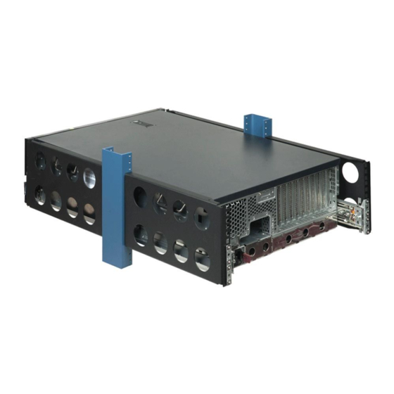
Page 22: Extend The Server From The Rack
If necessary, remove the tower bezel. For operations involving removable media bay access, the media bay panel may be removed. Extend the server from the rack IMPORTANT: If the server is installed in a telco rack, remove the server from the rack to access internal components. -
Page 23: Remove The Rack Bezel
NOTE: The release latches will lock into place when the rails are fully extended. WARNING: To reduce the risk of personal injury or equipment damage, be sure that the rack is adequately stabilized before extending a component from the rack. WARNING: To reduce the risk of personal injury, be careful when pressing the server rail-release latches and sliding the server into the rack. - Page 24 Remove the access panel (on page 25). Remove the media drive blanks or installed media drives ("Installing a half-height or full-height media device" on page 54). Remove the two thumbscrews that secure the rack bezel to the top of the chassis. Pull the rack bezel away from the chassis.
-
Page 25: Install The Rack Bezel
Install the rack bezel Align the four hooks on the rack bezel with the keyholes on the metal frame, and install the rack bezel. Tighten both internal rack bezel thumbscrews. Remove the access panel WARNING: To reduce the risk of personal injury from hot surfaces, allow the drives and the internal system components to cool before touching them. -
Page 26: Install The Access Panel
NOTE: If the locking latch is locked, use a Torx T-15 screwdriver to unlock the latch. Install the access panel Place the access panel on top of the server with the hood latch open. Allow the panel to extend past the rear of the server approximately 0.8 cm (0.2 in). -
Page 27: Remove The Center Wall
Remove the center wall Power down the server (on page 20). Extend or remove the server from the rack ("Extend the server from the rack" on page 22). Remove the access panel. ("Remove the access panel" on page 25) Remove the processor air baffle (on page 26). Remove the full-length expansion boards ("Removing expansion boards"... -
Page 28: Setup
Registering the server..........................34 Optional installation services Delivered by experienced, certified engineers, HP Care Pack services help you keep your servers up and running with support packages tailored specifically for HP ProLiant systems. HP Care Packs let you integrate both hardware and software support into a single package. A number of service level options are available to meet your needs. -
Page 29: Rack Planning Resources
HP servers draw in cool air through the front door and expel warm air through the rear door. Therefore, the front and rear rack doors must be adequately ventilated to allow ambient room air to enter the cabinet, and the rear door must be adequately ventilated to allow the warm air to escape from the cabinet. -
Page 30: Temperature Requirements
CAUTION: If a third-party rack is used, observe the following additional requirements to ensure adequate airflow and to prevent damage to the equipment: • Front and rear doors—If the 42U rack includes closing front and rear doors, you must allow 5,350 sq cm (830 sq in) of holes evenly distributed from top to bottom to permit adequate airflow (equivalent to the required 64 percent open area for ventilation). -
Page 31: Rack Warnings
Because of the high ground-leakage currents associated with multiple servers connected to the same power source, HP recommends the use of a PDU that is either permanently wired to the building’s branch circuit or includes a nondetachable cord that is wired to an industrial-style plug. NEMA locking-style plugs or those complying with IEC 60309 are considered suitable for this purpose. -
Page 32: Identifying Tower Server Shipping Carton Contents
CAUTION: Protect the server from power fluctuations and temporary interruptions with a regulating uninterruptible power supply (UPS). This device protects the hardware from damage caused by power surges and voltage spikes and keeps the system in operation during a power failure. CAUTION: Do not operate the server for long periods with the access panel open or removed. -
Page 33: Setting Up A Tower Server
If you are installing the server into a telco rack, order the appropriate option kit at the RackSolutions.com website (http://www.racksolutions.com/hp). Follow the server-specific instructions on the website to install the rack brackets. CAUTION: Always plan the rack installation so that the heaviest item is on the bottom of the rack. Install the heaviest item first, and continue to populate the rack from the bottom to the top. -
Page 34: Powering Up And Configuring The Server
Press the F9 key when prompted during the boot process to change the server settings using RBSU. The system is set up by default for the English language. For more information on the automatic configuration, refer to the HP ROM-Based Setup Utility User Guide located on the Documentation CD. -
Page 35: Hardware Options Installation
Hardware options installation In this section Introduction ............................35 Processor option............................. 35 Memory options ............................. 41 Hot-plug hard drive options ........................48 SAS-SATA hard drive cage option......................51 Removable media device options ......................53 Redundant hot-plug fans option ........................ 57 Redundant hot-plug power supply option.................... - Page 36 IMPORTANT: Processor socket 1 must always be populated. If processor socket 1 is empty, the server does not power up. To install a processor: Power down the server (on page 20). Do one of the following: • Open or remove the tower bezel, as needed ("Open or remove the tower bezel"...
- Page 37 Open the processor retaining latch and the processor socket retaining bracket. Remove the processor socket protective cover. IMPORTANT: Be sure the processor remains inside the processor installation tool. Hardware options installation 37...
- Page 38 If the processor has separated from the installation tool, carefully re-insert the processor in the tool. Align the processor installation tool with the socket and install the processor. Hardware options installation 38...
- Page 39 Press down firmly until the processor installation tool clicks and separates from the processor, and then remove the processor installation tool. Close the processor socket retaining bracket and the processor retaining latch. Remove the protective cover from the heatsink. Hardware options installation 39...
- Page 40 CAUTION: To prevent thermal instability and damage to the server, do not separate the processor from the heatsink after assembling. Install the heatsink. NOTE: Your heatsink may appear different than shown. Close the heatsink retaining latches. Install the PPM. Hardware options installation 40...
-
Page 41: Memory Options
QuickSpecs on the HP website (http://www.hp.com). The Advanced Memory Protection option is configured in RBSU. By default, the server is set to Advanced ECC mode. For more information, refer to HP ROM-Based Setup Utility (on page 79). If the configured Hardware options installation 41... -
Page 42: Advanced Ecc Memory
FBDIMMS must be ECC Registered DDR-2 SDRAM FBDIMMs. • FBDIMMs must be installed in pairs. • FBDIMM pairs in a memory bank must have identical HP part numbers. • FBDIMMS must be populated as specified for each AMP memory mode. •... -
Page 43: Online Spare Memory
Memory board 1 Bank A Bank B Bank C Bank D configuration 1A and 5A 2B and 6B 3C and 7C 4D and 8D Memory board 2 configuration — — — — — — — — — — — — —... -
Page 44: Mirrored Memory
For optimum memory usage, HP recommends all DIMMs on a memory board be the same size with the same HP part number. If different sized DIMMs are used on a memory board, a portion of the installed memory may not be utilized. -
Page 45: Memory Boards And Fbdimms
• Each bank of memory board 1 must be populated using FBDIMMs with identical HP part numbers to the corresponding bank of memory board 2. • Mirrored memory does not support any hot-plug operations. In mirroring mode, FBDIMMs must be populated as specified in the following table. - Page 46 Remove the memory board and place it on a flat surface. Do one of the following: • Remove a FBDIMM ("Removing FBDIMMs" on page 47). • Install a FBDIMM ("Installing FBDIMMs" on page 48). Align the memory board with the memory slot and the memory board guide clips. Install the memory board.
- Page 47 FBDIMM installation guidelines Always observe the following guidelines when installing additional memory: • Always install memory in pairs of equal capacity. • Install FBDIMMs into both slots within a single bank. • Always install memory in pairs in sequential bank order, starting with bank A. •...
-
Page 48: Hot-Plug Hard Drive Options
Installing FBDIMMs Power down the server (on page 20). Do one of the following: • Open or remove the tower bezel, as needed ("Open or remove the tower bezel" on page 21). • Extend the server from the rack (on page 22). Remove the access panel (on page 25). -
Page 49: Installing A Hot-Plug Hard Drive
Installing a hot-plug hard drive Remove the hard drive blank. Prepare the hard drive. Hardware options installation 49... -
Page 50: Removing A Hot-Plug Hard Drive
Install the hard drive. Determine the status of the hard drive from the hot-plug SAS hard drive LED combinations ("SAS and SATA hard drive LED combinations" on page 16). Removing a hot-plug hard drive CAUTION: To prevent improper cooling and thermal damage, do not operate the server unless all bays are populated with either a component or a blank. -
Page 51: Sas-Sata Hard Drive Cage Option
SAS-SATA hard drive cage option NOTE: An optional SAS controller is required to support the SAS-SATA hard drive cage installation. Power down the server. ("Power down the server" on page 20) Do one of the following: • Open or remove the tower bezel, as needed ("Open or remove the tower bezel"... - Page 52 Slide the hard drive cage into the drive bay and insert the four screws to secure the drive cage to the chassis. Connect the two SAS-SATA data cables to the drive cage backplane. NOTE: The center wall is removed for illustration purposes only. Hardware options installation 52...
-
Page 53: Removable Media Device Options
NOTE: HP recommends that you move the CD-ROM drive out of the media cabling area for ease of installation. It is not necessary to disconnect and remove the CD-ROM drive from the server entirely. -
Page 54: Installing A Half-Height Or Full-Height Media Device
Remove the media blanks. NOTE: HP recommends that you remove all media blanks to facilitate drive installation. Store the blanks for later use. Installing a half-height or full-height media device You can install up to two half-height or one full-height removable media devices in the removable media cage. - Page 55 Using the T-15 Torx screwdriver, remove the screws from the bezel blank and install them on the device. Slide the media device part of the way into the bay. • Half-height device Hardware options installation 55...
- Page 56 • Full-height device Connect the four-pin power cable to the half-height or full-height drive. Connect the data and power cables to the device. Connect the power cable to the system board. Connect the data cable to the system board or to an expansion board as directed by the option documentation.
-
Page 57: Redundant Hot-Plug Fans Option
Do one of the following: • Close or install the tower bezel, as needed. • Slide the server back into the rack. Power up the server (on page 20). Redundant hot-plug fans option The server supports redundant hot-plug fans to provide proper airflow to the system if a primary fan fails. In the standard configuration, fans 1, 2 and 3 cool the server. -
Page 58: Redundant Hot-Plug Power Supply Option
Redundant hot-plug power supply option The server supports a second hot-plug power supply to provide redundant power to the system in the event of a failure in the primary power supply. CAUTION: If only one power supply is installed, do not remove the power supply unless the server has been powered down. -
Page 59: Expansion Board Options
Use the power cord management clip to secure the cord and form a service loop. Connect the power cord to the power source. Be sure that the power supply LED is green ("Rear panel LEDs" on page 12). Be sure that the front panel external health LED is green ("Front panel LEDs and buttons"... -
Page 60: Performance Balancing
Performance balancing Balancing is the paired arrangement of PCI-X expansion boards for optimal performance based on the bus architecture of the expansion slots. When populating boards on a shared bus, be sure that both boards operate at the same speed (two PCI boards or two PCI-X boards). If boards with different speeds are used, the bus performs at the speed of the slowest board. -
Page 61: Installing Expansion Boards
Store the slot cover for future use. CAUTION: To prevent improper cooling and thermal damage, do not operate the server unless all PCI slots have either an expansion slot cover or an expansion board installed. Installing expansion boards CAUTION: To prevent damage to the server or expansion boards, power down the server and remove all AC power cords before removing or installing the expansion boards. -
Page 62: Removing Expansion Boards
Close the slot release lever and lock the retainer clip. Connect any required internal or external cables to the expansion board. Refer to the documentation that ships with the expansion board. Install the access panel. Do one of the following: •... -
Page 63: Array Controllers And Battery-Backed Write Cache Options
CAUTION: Make a note of board locations. Be sure to install replacements in the same slots. Array controllers and Battery-Backed Write Cache options For a list of supported options, refer to the Documentation CD or the QuickSpecs on the HP website (http://www.hp.com/servers/proliantml370). -
Page 64: Tower-To-Rack Conversion Option
Power up the server (on page 20). Enable the feature under the System Options menu in RBSU. For more information on RBSU, refer to the HP ROM-Based Setup Utility User Guide on the Documentation CD or the HP website (http://www.hp.com/servers/smartstart). - Page 65 Power down the server (on page 20). Remove the feet. Remove the tower bezel ("Open or remove the tower bezel" on page 21). Remove the tower configuration panels: Use the Torx T-15 screwdriver to remove the two front panel screws. Remove the tower configuration panels.
- Page 66 Remove the media blanks. Remove the access panel (on page 25). Remove the center wall (on page 27). Remove the CD-ROM drive. Press and slide the media latch. Release the CD-ROM drive from the back and push it forward to better access the cables. Hardware options installation 66...
- Page 67 Disconnect the IDE CD-ROM drive cable and power cable from the back of the drive. Remove the CD-ROM drive. Press and slide the media latch to remove the media bay spacer. Hardware options installation 67...
- Page 68 Remove the two clips on the server. Align the four hooks on the rack bezel with the keyholes on the metal frame, and install the rack bezel. Hardware options installation 68...
- Page 69 Tighten both internal rack bezel thumbscrews. Partially insert the CD-ROM drive horizontally into the slot below the media bay spacer. Connect the IDE CD-ROM drive cable and power cable. Push the CD-ROM drive all the way into the bay until the locking latch clicks into place, securing the drive.
- Page 70 Remove the video connector blank from the media bay spacer. Install the front video connector and thread the cable through the clip on the media bay spacer. Hardware options installation 70...
- Page 71 Install the media bay spacer into the top slot of the media bay. Connect the front video connector cable to the internal video connector. Install the center wall. Install the access panel. Install the server into the rack ("Installing the server into the rack"...
-
Page 72: Cabling
Cabling In this section Storage device cabling guidelines......................72 Cable connector identification ......................... 72 SAS cabling ............................73 CD-ROM drive cabling ........................... 74 Video cabling ............................75 Parallel/serial port cabling ........................75 Diskette drive cabling ..........................76 BBWC option cabling..........................76 Internal USB connector.......................... -
Page 73: Sas Cabling
Item Description Fan control/HP Systems Insight Display connector IDE connector Power connector SAS drive connector (5-8) SAS power connector SAS drive connector (1-4) SAS drive connector (13-16) SAS power connector SAS drive connector (9-12) SAS cabling NOTE: The center wall is removed for illustration purposes only. -
Page 74: Cd-Rom Drive Cabling
• SAS power cabling CD-ROM drive cabling Cabling 74... -
Page 75: Video Cabling
Video cabling Parallel/serial port cabling Cabling 75... -
Page 76: Diskette Drive Cabling
Diskette drive cabling BBWC option cabling Cabling 76... -
Page 77: Internal Usb Connector
Internal USB connector Cabling 77... -
Page 78: Configuration And Utilities
Enabling access to the Array Configuration Utility (on page 80), Array Diagnostic Utility (on page 86), and Erase Utility SmartStart is included in the HP ProLiant Essentials Foundation Pack. For more information about SmartStart software, refer to the HP ProLiant Essentials Foundation Pack or the HP website (http://www.hp.com/servers/smartstart). -
Page 79: Hp Rom-Based Setup Utility
Configuring memory options • Language selection For more information on RBSU, refer to the HP ROM-Based Setup Utility User Guide on the Documentation CD or the HP website (http://www.hp.com/servers/smartstart). Using RBSU The first time you power up the server, the system prompts you to enter RBSU and select a language. -
Page 80: Array Configuration Utility
Servers running Microsoft® operating systems require Internet Explorer 5.5 (with Service Pack 1) or later. For Linux servers, refer to the README.TXT file for additional browser and support information. For more information, refer to the HP Array Configuration Utility User Guide on the Documentation CD or the HP website (http://www.hp.com). -
Page 81: Option Rom Configuration For Arrays
RBSU by pressing the F9 key when prompted. After the settings are selected, exit RBSU and allow the server to reboot automatically. For more information, refer to the HP ROM-Based Setup Utility User Guide on the Documentation CD or the HP website (http://www.compaq.com/support/techpubs/whitepapers). -
Page 82: Re-Entering The Server Serial Number And Product Id
ASR increases server availability by restarting the server within a specified time after a system hang or shutdown. At the same time, the HP SIM console notifies you by sending a message to a designated pager number that ASR has restarted the system. You can disable ASR from the HP SIM console or through RBSU. -
Page 83: System Online Rom Flash Component Utility
HP website (http://www.hp.com/servers/lights-out). iLO ROM-Based Setup Utility HP recommends using iLO RBSU to configure and set up iLO. iLO RBSU is designed to assist you with setting up iLO on a network; it is not intended for continued administration. -
Page 84: Storageworks Library And Tape Tools
HP SIM provides device management capabilities that consolidate and integrate management data from HP and third-party devices. IMPORTANT: You must install and use HP SIM to benefit from the Pre-Failure Warranty for processors, SAS and SCSI hard drives, and memory modules. -
Page 85: Usb Support And Functionality
Internal USB functionality (on page 86) USB support HP provides both standard USB support and legacy USB support. Standard support is provided by the operating system through the appropriate USB device drivers. HP provides support for USB devices before the operating system loads through legacy USB support, which is enabled by default in the system ROM. -
Page 86: Diagnostic Tools
If a significant change occurs between data-gathering intervals, the Survey Utility marks the previous information and overwrites the Survey text files to reflect the latest changes in the configuration. Survey Utility is installed with every SmartStart-assisted installation or can be installed through the HP PSP ("ProLiant Support Packs"... -
Page 87: Integrated Management Log
From within the iLO 2 user interface • From within HP Insight Diagnostics (on page 86) For more information, refer to the Management CD in the HP ProLiant Essentials Foundation Pack. Remote support and analysis tools HP Instant Support Enterprise Edition ISEE is a proactive remote monitoring and diagnostic tool to help manage your systems and devices, a feature of HP support. -
Page 88: Proliant Support Packs
Refer to the operating system support matrix (http://www.hp.com/go/supportos). Change control and proactive notification HP offers Change Control and Proactive Notification to notify customers 30 to 60 days in advance of upcoming hardware and software changes on HP commercial products. For more information, refer to the HP website (http://h18023.www1.hp.com/solutions/pcsolutions/pcn.html). -
Page 89: Battery Replacement
Battery replacement If the server no longer automatically displays the correct date and time, you may need to replace the battery that provides power to the real-time clock. Under normal use, battery life is 5 to 10 years. WARNING: The computer contains an internal lithium manganese dioxide, a vanadium pentoxide, or an alkaline battery pack. -
Page 90: Troubleshooting
To obtain the guide, refer to any of the following sources and then select the HP ProLiant Servers Troubleshooting Guide: •... -
Page 91: Warnings And Cautions
Warnings and cautions WARNING: Only authorized technicians trained by HP should attempt to repair this equipment. All troubleshooting and repair procedures are detailed to allow only subassembly/module-level repair. Because of the complexity of the individual boards and subassemblies, no one should attempt to make repairs at the component level or to make modifications to any printed wiring board. -
Page 92: Symptom Information
If the problem occurs randomly, what is the duration or frequency? To answer these questions, the following information may be useful: • Run HP Insight Diagnostics (on page 86) and use the survey page to view the current configuration or to compare it to previous configurations. •... -
Page 93: Prepare The Server For Diagnosis
NOTE: To verify the server configuration, connect to the System Management homepage and select Version Control Agent. The VCA gives you a list of names and versions of all installed HP drivers, Management Agents, and utilities, and whether they are up to date. -
Page 94: Troubleshooting Flowcharts
Troubleshooting flowcharts To effectively troubleshoot a problem, HP recommends that you start with the first flowchart in this section, "Start diagnosis flowchart (on page 94)," and follow the appropriate diagnostic path. If the other flowcharts do not provide a troubleshooting solution, follow the diagnostic steps in "General diagnosis flowchart (on page 95)."... -
Page 95: General Diagnosis Flowchart
General diagnosis flowchart The General diagnosis flowchart provides a generic approach to troubleshooting. If you are unsure of the problem, or if the other flowcharts do not fix the problem, use the following flowchart. Item Refer to "Symptom information (on page 92)" "Loose connections (on page 93)"... - Page 96 HP ROM-BIOS/Firmware Updates website (http://h18023.www1.hp.com/support/files/server/us/romflash.ht "General memory problems are occurring" in the HP ProLiant Servers Troubleshooting Guide located on the Documentation CD or on the HP website (http://www.hp.com/support) Server maintenance and service guide, located on the Documentation CD or the HP website (http://www.hp.com/products/servers/platforms) •...
-
Page 97: Server Power-On Problems Flowchart
Server power-on problems flowchart Symptoms: • The server does not power on. • The system power LED ("Systems Insight Display LEDs" on page 10) is off or amber. • The external health LED ("Systems Insight Display LEDs" on page 10) is red or amber. Troubleshooting 97... - Page 98 Faulty internal component Item Refer to "Component identification (on page 7)" "HP Insight Diagnostics (on page 86)" or in the HP ProLiant Servers Troubleshooting Guide located on the Documentation CD or on the HP website (http://www.hp.com/support) "Loose connections (on page 93)"...
- Page 99 Troubleshooting 99...
-
Page 100: Post Problems Flowchart
"Symptom information (on page 92)" Server maintenance and service guide, located on the Documentation CD or the HP website (http://www.hp.com/products/servers/platforms) "Port 85 and iLO messages" in the HP ProLiant Servers Troubleshooting Guide located on the Documentation CD or on the HP website (http://www.hp.com/support) "General memory problems are occurring"... -
Page 101: Os Boot Problems Flowchart
OS boot problems flowchart Symptoms: • Server does not boot a previously installed operating system • Server does not boot SmartStart Possible causes: • Corrupted operating system • Hard drive subsystem problem • Incorrect boot order setting in RBSU Troubleshooting 101... - Page 102 Guide located on the Documentation CD or on the HP website (http://www.hp.com/support) • Controller documentation "HP Insight Diagnostics (on page 86)" or in the HP ProLiant Servers Troubleshooting Guide located on the Documentation CD or on the HP website (http://www.hp.com/support) •...
-
Page 103: Server Fault Indications Flowchart
Server fault indications flowchart Symptoms: • Server boots, but a fault event is reported by Insight Management Agents (on page 84) • Server boots, but the internal health LED, external health LED, or component health LED is red or amber NOTE: For the location of server LEDs and information on their statuses, refer to the server documentation. - Page 104 Documentation CD or the HP website (http://www.hp.com/products/servers/platforms) • "HP contact information (on page 115)" "HP Insight Diagnostics (on page 86)" or in the HP ProLiant Servers Troubleshooting Guide located on the Documentation CD or on the HP website (http://www.hp.com/support) •...
-
Page 105: Post Error Messages And Beep Codes
POST error messages and beep codes For a complete listing of error messages, refer to the "POST error messages" in the HP ProLiant Servers Troubleshooting Guide located on the Documentation CD or on the HP website (http://www.hp.com/support). WARNING: To avoid potential problems, ALWAYS read the warnings and cautionary information in the server documentation before removing, replacing, reseating, or modifying system components. -
Page 106: Electrostatic Discharge
Electrostatic discharge In this section Preventing electrostatic discharge......................106 Grounding methods to prevent electrostatic discharge ................106 Preventing electrostatic discharge To prevent damaging the system, be aware of the precautions you need to follow when setting up the system or handling parts. A discharge of static electricity from a finger or other conductor may damage system boards or other static-sensitive devices. -
Page 107: Regulatory Compliance Notices
Regulatory compliance notices In this section Regulatory compliance identification numbers..................107 Federal Communications Commission notice ................... 107 Declaration of conformity for products marked with the FCC logo, United States only........108 Modifications............................109 Cables ..............................109 Canadian notice (Avis Canadien) ......................109 European Union regulatory notice ...................... -
Page 108: Class A Equipment
Hewlett-Packard Company P. O. Box 692000, Mail Stop 530113 Houston, Texas 77269-2000 • 1-800-HP-INVENT (1-800-474-6836). (For continuous quality improvement, calls may be recorded or monitored.) For questions regarding this FCC declaration, contact us by mail or telephone: • Hewlett-Packard Company P. -
Page 109: Modifications
Modifications The FCC requires the user to be notified that any changes or modifications made to this device that are not expressly approved by Hewlett-Packard Company may void the user’s authority to operate the equipment. Cables Connections to this device must be made with shielded cables with metallic RFI/EMI connector hoods in order to maintain compliance with FCC Rules and Regulations. -
Page 110: Disposal Of Waste Equipment By Users In Private Households In The European Union
Disposal of waste equipment by users in private households in the European Union This symbol on the product or on its packaging indicates that this product must not be disposed of with your other household waste. Instead, it is your responsibility to dispose of your waste equipment by handing it over to a designated collection point for the recycling of waste electrical and electronic equipment. -
Page 111: Korean Notice
• Allow only HP Authorized Service technicians to repair the unit. The Center for Devices and Radiological Health (CDRH) of the U.S. Food and Drug Administration implemented regulations for laser products on August 2, 1976. These regulations apply to laser products manufactured from August 1, 1976. -
Page 112: Taiwan Battery Recycling Notice
Batteries, battery packs, and accumulators should not be disposed of together with the general household waste. To forward them to recycling or proper disposal, please use the public collection system or return them to HP, an authorized HP Partner, or their agents. -
Page 113: Specifications
Specifications In this section Server specifications ..........................113 Environmental specifications ........................113 Server specifications Specification Value Dimensions Height 21.92 cm (8.63 in) Depth 65.41 cm (26.5 in) Width 44.45 cm (17.50 in) Weight (maximum) 40.8 kg (110 lb) Weight (no drives installed) 24.9 kg (55 lb) Input Requirements Rated input voltage... - Page 114 * All temperature ratings shown are for sea level. An altitude derating of 1°C per 300 m (1.8°F per 1,000 ft) to 3048 m (10,000 ft) is applicable. No direct sunlight allowed. ** Storage maximum humidity of 95% is based on a maximum temperature of 45°C (113°F). Altitude maximum for storage corresponds to a pressure minimum of 70 KPa.
-
Page 115: Technical Support
• In North America: • Call 1-800-HP-INVENT (1-800-474-6836). This service is available 24 hours a day, 7 days a week. For continuous quality improvement, calls may be recorded or monitored. • If you have purchased a Care Pack (service upgrade), call 1-800-633-3600. For more information about Care Packs, refer to the HP website (http://www.hp.com). -
Page 116: Customer Self Repair
HP specifies in the materials shipped with a replacement CSR part whether a defective part must be returned to HP. In cases where it is required to return the defective part to HP, you must ship the defective part back to HP within a defined period of time, normally five (5) business days. - Page 117 La mancata restituzione del componente può comportare la fatturazione del ricambio da parte di HP. Nel caso di riparazione da parte del cliente, HP sostiene tutte le spese di spedizione e resa e sceglie il corriere/vettore da utilizzare.
- Page 118 Si no enviara el componente defectuoso requerido, HP podrá cobrarle por el de sustitución. En el caso de todas sustituciones que lleve a cabo el cliente, HP se hará cargo de todos los gastos de envío y devolución de componentes y escogerá la empresa de transporte que se utilice para dicho servicio.
- Page 119 Opcional – Peças cujo reparo feito pelo cliente é opcional. Essas peças também são projetadas para o reparo feito pelo cliente. No entanto, se desejar que a HP as substitua, pode haver ou não a cobrança de taxa adicional, dependendo do tipo de serviço de garantia destinado ao produto.
- Page 120 HP para que um técnico o ajude por telefone. A HP especifica nos materiais fornecidos com a peça CSR de reposição se a peça com defeito deve ser devolvida à HP. Nos casos em que isso for necessário, é preciso enviar a peça com defeito à HP dentro do período determinado, normalmente cinco (5) dias úteis.
- Page 121 Technical support 121...
- Page 122 Technical support 122...
-
Page 123: Acronyms And Abbreviations
Acronyms and abbreviations ABEND abnormal end Array Configuration Utility Advanced Memory Protection Automatic Server Recovery BBWC battery-backed write cache double data rate DIMM dual inline memory module error checking and correcting FBDIMM fully buffered DIMM International Electrotechnical Commission iLO 2 Integrated Lights-Out 2 Integrated Management Log Acronyms and abbreviations 123... - Page 124 NEMA National Electrical Manufacturers Association NFPA National Fire Protection Association network interface controller NVRAM non-volatile memory ORCA Option ROM Configuration for Arrays PCI-X peripheral component interconnect extended power distribution unit POST Power-On Self Test processor power module ProLiant Support Pack RBSU ROM-Based Setup Utility Systems Insight Manager...
- Page 125 VHDCI very high density cable interconnect Acronyms and abbreviations 125...
-
Page 126: Index
AC power supply 12, 58 connection problems 93 access panel 25 connectors 7, 11, 13, 72, 77 ACU (Array Configuration Utility) 80 contacting HP 115 additional information 115 creating a disk image 81 ADU (Array Diagnostic Utility) 86 CSR (customer self repair) 116... - Page 127 LEDs 9 Natural Language Search Assistant 88 HP Insight Diagnostics 86 network connector LEDs 12 HP ProLiant Essentials Foundation Pack 34, 84 NIC (network interface controller) 124 HP ProLiant Essentials Rapid Deployment Pack 81 NIC LEDs 9, 10 HP Systems Insight Manager, overview 84...
- Page 128 power distribution unit 30 service notifications 93 power LEDs, system 9 shipping carton contents 32 Power On/Standby button 9, 20 SmartStart autorun menu 78 power requirements 30 SmartStart Scripting Toolkit 78 power supplies 12, 58 SmartStart software 34 power supply backplane LED 18 SmartStart, overview 78 power supply LEDs 12, 14 space requirements 29...
- Page 129 warnings 91 Index 129...
Need help?
Do you have a question about the ProLiant ML370 G5 and is the answer not in the manual?
Questions and answers