Table of Contents
Advertisement
Quick Links
Advertisement
Table of Contents

Related Manuals for Advantech IDK-1119R-35SXA1E


Summary of Contents for Advantech IDK-1119R-35SXA1E
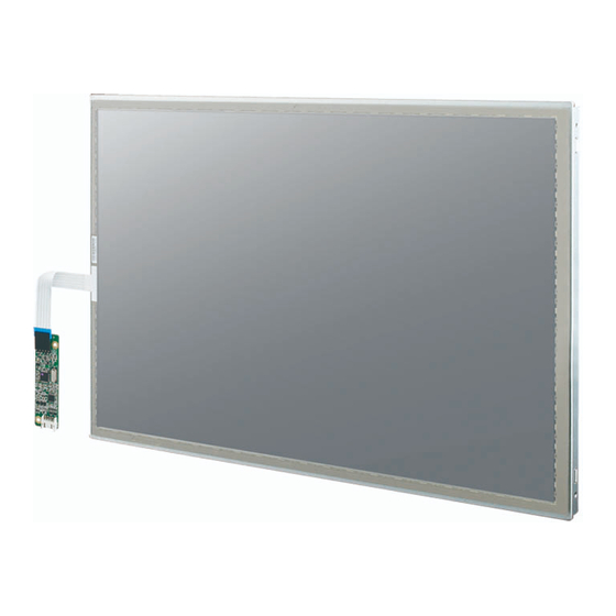
- Page 1 User Manual IDK-1119R-35SXA1E TFT-LCD 19" SXGA (LED Backlight)
- Page 2 No part of this manual may be reproduced, copied, translated or transmitted in any form or by any means without the prior written permission of Advantech Co., Ltd. Information provided in this manual is intended to be accurate and reliable. How- ever, Advantech Co., Ltd.
- Page 3 Whether your new Advantech equipment is destined for the labo- ratory or the factory floor, you can be assured that your product will provide the reliability and ease of operation for which the name Advantech has come to be known.
- Page 4 Because of Advantech’s high quality-control standards and rigorous testing, most of our customers never need to use our repair service. If an Advantech product is defec- tive, it will be repaired or replaced at no charge during the warranty period. For out- of-warranty repairs, you will be billed according to the cost of replacement materials, service time and freight.
-
Page 5: Table Of Contents
Contents Chapter Overview..........1 General Description .................. 2 Display Characteristics................2 Functional Block Diagram ................. 3 Figure 1.1 Function block diagram ..........3 Absolute Maximum Ratings ..............3 1.4.1 Absolute Ratings of TFT LCD Module .......... 3 1.4.2 Absolute Ratings of Backlight Unit..........3 1.4.3 Absolute Ratings of Environment.......... - Page 6 Chapter Touch Controller ....... 25 Touch Controller Characteristics............. 26 6.1.1 Specifications................26 6.1.2 Environmental Features.............. 26 Pin Assignment and Description ............. 27 6.2.1 Connector and LED Location............27 6.2.2 Combo Interface Connector, JP1, Pins and Signal Descriptions 27 Figure 6.1 Board mounted header..........28 6.2.3 Touch Screen Connector, JP2, Pins and Signal Descriptions..
-
Page 7: Chapter 1 Overview
Chapter Overview... -
Page 8: General Description
General Description IDK-1119R-35SXA1E is a Color Active Matrix Liquid Crystal Display composed of a TFT-LCD panel, a driver circuit, and backlight system. The screen format is intended to support the SXGA (1280H x 1024V) screen and 16.7M colors (RGB 6-bits with HiFRC data). -
Page 9: Functional Block Diagram
Functional Block Diagram The following diagram shows the functional block of the 19 inches Color TFT-LCD Module: Figure 1.1 Function block diagram Absolute Maximum Ratings Absolute maximum ratings of the module is as following: 1.4.1 Absolute Ratings of TFT LCD Module Item Symbol Min. -
Page 10: Outline Dimension
Note2: Permanent damage to the device may occur if exceed maximum values Note3: For quality performance, please refer to AUO IIS (Incoming Inspection Stan- dard). Outline Dimension 1.5.1 Front View IDK-1119R User Manual... -
Page 11: Rear View
1.5.2 Rear View IDK-1119R User Manual... - Page 12 IDK-1119R User Manual...
-
Page 13: Chapter 2 Electrical Characteristics
Chapter Electrical Characteristics... -
Page 14: Power Specification
Power Specification Input power specifications are as follows: Table 2.1: Power specification Symbol Parameter Min. Typ. Max. Unit Condition ± Logic/LCD Drive [Volt] Voltage Input Current 0.94 Vin=5V, at 60Hz All black pattern IRush Inrush Current Note 2 VCCPower [Watt] Vin=5V, at 60Hz) All black pattern VCCrp... -
Page 15: Backlight Unit
Note 3 IF, VF , PLED are defined for LED Light Bar. Note 4 If IDK-1119R-35SXA1E module is driven by high current or at high ambient temperature & humidity condition. The operating life will be reduced. Note 5 Operating life means brightness goes down to 50% initial brightness. Mini- mum operating lifetime is estimated data. - Page 16 IDK-1119R User Manual...
-
Page 17: Chapter 3 Signal Characteristics
Chapter Signal Characteristics... -
Page 18: Pixel Format Image
Pixel Format Image Following figure shows the relationship between input signal and LCD pixel format. The Input Data Format Note 1 Normally DE mode only. VS and HS on EVEN channel are not used. Note 2 Please follow VESA. Note 3 8-bit in IDK-1119R User Manual... -
Page 19: Signal Description
Signal Description The module using a pair of LVDS receiver SN75LVDS82 (Texas Instruments) or com- patible. LVDS is a differential signal technology for LCD interface and high speed data transfer device. Transmitter shall be SN75LVDS83 (negative edge sampling) or compatible. The first LVDS port (RxOxxx) transmits odd pixels while the second LVDS port (RxExxx) transmits even pixels. -
Page 20: Interface Timing
Note1 Input signals of odd and even clock shall be the same timing. And start from the left side. Note2 Input signals of add and even clock shall be the same timing Note3 Please follow VESA. Interface Timing 3.4.1 Timing Characteristics Table 3.2: Timing Characteristics Signal Parameter... -
Page 21: Input Timing Diagram
3.4.2 Input Timing Diagram Power ON/OFF Sequence VDD power and LED on/off sequence is as follows. Interface signals are also shown in the chart. Signals from any system shall be Hi-Z state or low level when VDD is off. Power Sequence Timing Parameter Value Unit... - Page 22 [ms] [ms] 1000 IDK-1119R User Manual...
-
Page 23: Chapter 4 Connector & Pin Assignment
Chapter Connector & Pin Assignment... -
Page 24: Tft Lcd Module
TFT LCD Module Physical connector pins are assigned the following signals. 4.1.1 Connector Table 4.1: Connector Connector Name / Designation Interface Connector / Interface card Manufacture JAE / P-TWO Type Part Number FI-XB30SSLA-HF15 / 187034-30091 Mating Housing Part Number FI-X30HL FI-X30H (Unlocked Type) 4.1.2 Pin Assignment... - Page 25 +12V Power +12V +12V Power +12V Enable(max.5V) Dimming PWM (duty 10%~ 100%) IDK-1119R User Manual...
- Page 26 IDK-1119R User Manual...
-
Page 27: Chapter 5 Touch Screen
Chapter Touch Screen... -
Page 28: Touch Characteristics
Touch Characteristics This touch panel uses a 5-wire Analog resistance type that customers use with flat displays like LCDs. Once a user touches it with a stylus or finger, the circuit sends coordinate points from voltages to the CPU at the contact point. Optical Characteristics Item Specification... -
Page 29: General Specifications
General Specifications Item Specification Frame size 393.40±0.50 X 316.65±0.50 mm View Area 380.90±0.20 X 305.65±0.20 mm Active Area 377.30±0.20 X 302.05±0.20 mm Total Thickness 3.20±0.20 mm Tail length 305.00±6.00 mm IDK-1119R User Manual... - Page 30 IDK-1119R User Manual...
-
Page 31: Touch Controller
Chapter Touch Controller... -
Page 32: Touch Controller Characteristics
Advantech ETM-RES04C Touch Control Board is the ultimate combo board. This touch panel controller provides optimum performance for your analog resistive touch panels for 5 wire models. It communicates with the PC directly through USB and RS- 232 connectors. The touch panel driver emulates mouse left and right button func- tions. -
Page 33: Pin Assignment And Description
– 95% at 60°C, RH Non-condensing Acquired RoHS certificate Requlatory FCC-B, CE approvals Dimension: 75 mm x 20 mm x 10 mm Pin Assignment and Description 6.2.1 Connector and LED Location JP2 Connector JP1 Connector (USB&RS-232 (5-wire Touch screen Combo Interface) Interface) 6.2.2 Combo... -
Page 34: Combo Interface Connector, Jp1, Pins And Signal Descriptions 27 Figure 6.1 Board Mounted Header
Figure 6.1 Board mounted header 6.2.3 Touch Screen Connector, JP2, Pins and Signal Descriptions The Touch Screen connector, JP2, is a single row by 2.54mm 5-pins 90 degree, Male type connector. The pins are numbered as shown in the table below. JP2 Pin # Signal Name Signal Description... -
Page 35: Optical Characteristics
Appendix Optical Characteristics... - Page 36 The optical characteristics are measured under stable conditions at 25°C (Room Temperature): Item Unit Conditions Min. Typ. Max. Note Viewing Angle [degree] Horizontal (Right) CR = 10 (Left) Vertical (Up) CR = 10 (Down) Horizontal (Right) CR = 5 (Left) Vertical (Up) CR = 5...
- Page 37 Note 3 The luminance uniformity of 9 points is defined by dividing the maximum lumi- nance values by the minimum test point luminance Note 4 Measurement method The LCD module should be stabilized at given temperature for 20 minutes to avoid abrupt temperature change during measuring.
- Page 38 IDK-1119R User Manual...
-
Page 39: Handling Precautions
Appendix Handling Precautions... -
Page 40: Handling Precautions
Handling Precautions The optical characteristics are measured under stable conditions at 25°C (Room Temperature) Since front polarizer is easily damaged, pay attention not to scratch it. Be sure to turn off power supply when inserting or disconnecting from input con- nector. - Page 41 No part of this publication may be reproduced in any form or by any means, electronic, photocopying, recording or otherwise, without prior written permis- sion of the publisher. All brand and product names are trademarks or registered trademarks of their respective companies. © Advantech Co., Ltd. 2012...
Need help?
Do you have a question about the IDK-1119R-35SXA1E and is the answer not in the manual?
Questions and answers