
Related Manuals for Advantech POC-W242


Summary of Contents for Advantech POC-W242
- Page 1 User Manual POC-W242 Point-of-Care Terminal with Intel® Core™ i7 or i5 Processor and a 23.8’’ Full HD IPS LCD...
- Page 2 Repair of the device may also only be carried out by trained service personnel. Advantech recommends that a service contract be obtained with Advantech Service and that all repairs also be carried out by them. Otherwise the correct functioning of the device may be compromised.
- Page 3 The computer is provided with a battery-powered real-time clock circuit. There is a danger of explosion if battery is incorrectly replaced. Replace only with same or equivalent type recommended by the manufacture. Discard used batteries according to the manufacturer’s instructions POC-W242 User Manual...
- Page 4 Caution! When servicing the device, always use replacement parts that are quali- fied to Advantech standards. Advantech Medical cannot warrant or endorse the safe performance of third-party replacement parts for use with our medical device.
- Page 5 Warning! Do not modify this equipment without authorization of the manufacturer. Warning! To avoid risk of electric shock, this equipment must only be connected to a supply mains with protective earth. Caution! This adapter Sinpro HPU101-107 is a forming part of the medical device. POC-W242 User Manual...
- Page 6 The mark on electrical and electronic products only applies to the current European Union Member States. POC-W242 User Manual...
- Page 7 List of Accessories Before installing your Point of Care Terminal, ensure that the following materials have been received: POC-W242 series Point-of-Care Terminal Accessories for POC-W242 CD-ROM disc-"Drivers, User's manual and Utilities" Mounting kits and packet of screws.
- Page 8 Additional Information and Assistance Contact your distributor, sales representative, or Advantech's customer service cen- ter for technical support if you need additional assistance. Please have the following information ready before you call: Product name and serial number Description of your peripheral attachments ...
-
Page 9: Table Of Contents
......1 Introduction ....................2 Specifications .................... 2 Dimensions ....................4 Figure 1.1 Dimensions of the POC-W242 ........4 Figure 1.2 VESA Mounting of the POC-W242......4 Figure 1.3 POC-W242 Front Panel..........5 Figure 1.4 POC-W242 Front Functions ........5 Figure 1.5 POC-W242 Rear ............5 1.3.1... - Page 10 BIOS....35 Introduction ..................... 36 Appendix A POC-W242 VESA Mounting....39 Install VESA Mounting ................40 Figure A.1 Install VESA Mounting..........40 Appendix B ENERGY STAR ........41 What is ENERGY STAR? ............... 42 Power Management System..............42 POC-W242 User Manual...
-
Page 11: Chapter 1 General Information
Chapter General Information... -
Page 12: Introduction
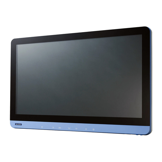
Introduction The POC-W242 is a multimedia Intel® Core™ i7 or i5 processor series designed for mobile computing as a Point-of-Care terminal (POC.) It is a PC-based system with 23.8'' wide screen TFT LCD display, single VGA Port, HDMI out, dual on-board 10/ 100/1000 PCI-E Ethernet controllers, and LAN ports. - Page 13 Shock Resistance 20G peak acceleration (11ms duration) Dimensions 583.38 x 386.75 x 69.42 mm(22.96" x 15.22" x Physical (W x H x D) 2.73") Characteristics Weight 7 kg (15.24 lb.) Platform & utility Windows 8, Windows 7 POC-W242 User Manual...
-
Page 14: Dimensions
Dimensions: 583.38 x 386.75 x 69.42 mm (Unit: mm) Figure 1.1 Dimensions of the POC-W242 VESA Mounting: 75 x 75 mm; 100 x 100 mm Figure 1.2 VESA Mounting of the POC-W242 Warning! Use suitable mounting apparatus to avoid risk of injury. POC-W242 User Manual... -
Page 15: Optional Modules
Figure 1.3 POC-W242 Front Panel (1) Power (2) Volume Up /Down (3) Touchscreen Status Control (4) Read Light Control (5) Brightness Increase/Decrease Figure 1.4 POC-W242 Front Functions (1) MIC-in and Speaker-out (2) 2 x USB 2.0 ports 2 3 4 Figure 1.5 POC-W242 Rear... -
Page 16: Point-Of-Care Terminal Cleaning And Disinfecting
Do not use disinfectants that contain phenol. Do not autoclave or clean the POC or its peripherals with strong aromatic, chlorinated, ketone, ether, or Esther solvents, sharp tools or abrasives. Never immerse electrical connectors in water or other liquids. POC-W242 User Manual... -
Page 17: Chapter 2 System Setup
Chapter System Setup... -
Page 18: A Quick Tour Of The Poc-W242
A Quick Tour of the POC-W242 Before you start to set up the POC-W242, take a moment to become familiar with the locations and purposes of the controls, drives, connections and ports, which are illus- trated in the figures below. -
Page 19: Rear View
Installation Procedures 2.2.1 Connecting the power cord The POC-W242 could only be powered by a DC power adapter (SINPRO Model no.HPU101-107). Be sure to always handle the power cords by holding the plug ends only. Follow these procedures in order: Connect the female end of the power adapter to the DC jack of the panel PC. -
Page 20: Connecting The Ground Pin
Switching on the power Push down the power button on the front panel for POC-W242. (The color of the indi- cation is green) 2.2.2 Connecting the Ground pin 1.With system ready, find the equiotential terminal on the rear side of the POC. -
Page 21: Running The Bios Setup Program
Grounding cable plug with Equipotential Terminal Running the BIOS Setup Program Your POC-W242 is likely to have been properly set up and configured by your dealer prior to delivery. You may still find it necessary to use the BIOS (Basic Input-Output System) setup program to change system configuration information, such as the cur- rent date and time or your type of hard drive. -
Page 22: Trouble Shooting
Guidance and manufacturer’s declaration – electromagnetic emissions The model POC-W242 is intended for use in the electromagnetic environment specified below. The customer or the user of the model POC-W242 should assure that it is used in such an environment. Electromagnetic environment –... - Page 23 Recommended separation distances between portable and mobile RF communications equipment and the model POC-W242 The model POC-W242 is intended for use in an electromagnetic environment in which radi- ated RF disturbances are controlled. The customer or the user of the model POC-W242...
- Page 24 Guidance and manufacturer’s declaration – electromagnetic immunity The model POC-W242 is intended for use in the electromagnetic environment specified below. The customer or the user of the model POC-W242 should assure that it is used in such an environment. IEC 60601 test...
- Page 25 Guidance and manufacturer’s declaration – electromagnetic immunity The model POC-W242 is intended for use in the electromagnetic environment specified below. The customer or the user of the model POC-W242 should assure that it is used in such an environment. Immunity...
- Page 26 RF transmitters, an electromagnetic site survey should be consid- ered. If the measured field strength in the location in which the model POC-W242 is used exceeds the applicable RF compliance level above, the model POC-W242 should be observed to verify normal operation.
-
Page 27: Chapter 3 Driver Installation
Chapter Driver installation... -
Page 28: Introduction
Introduction The POC-W242 supports "one key" driver installation. User can just click one button to install all drivers. Warning! Please use clean OS to install this auto installation, otherwise, it might cause un-expect error. Windows Driver List: Please follow your OS version (WIN7 32 bits, WIN7 64 bits, WIN8) to install proper driver. -
Page 29: Chapter 4 Operation And Safety Information
Chapter Operation and Safety Information... -
Page 30: General Safety Guide
You want to remove/install any parts Thermal The vent hole of the POC-W242 rear cover functions as a cooling air flow inlet and outlet. These air inlet and outlet transfer heat from inside the computer to the cooler air outside. Do not block these holes/vents by any soft material. -
Page 31: Proper Handling
Proper Handling Handle your POC-W242 with care. It is made of metal, glass, and plastic and has sensitive electronic components inside. Don't use a damaged POC-W242, such as one with a cracked screen, as it may cause injury. Setup POC-W242 on a stable work surface. - Page 32 POC-W242 User Manual...
-
Page 33: Chapter 5 Pcm-8715 Connector Map & Table
Chapter PCM-8715 Connector Map & Table... -
Page 34: Mb Top Side
MB TOP Side POC-W242 User Manual... -
Page 35: Mb Bottom Side
DDR3L SODIMM 1 Socket SATA 1 Connector SATA 1 Power Connector or PCAP Touch USB Connector Camera/USB (12V and 3.3V) Connector USB (5V) Connector Mini PCIe (Half Size) Socket 5 wires resistive Touch Connect Mini PCIe (Full Size) Socket POC-W242 User Manual... -
Page 36: Io Board
USB Connector (5V, Reserved) Smart Card/USB (5V) Connector USB ISO/USB (12V/5V) Connector USB Connector (5V) COM4 (RS232, Reserved) Internal Backup Battery Connector Reset EC button COM1 (RS232/422/485) USB3.0 COM2 (RS232) COM3 (RS232) LAN1 (iAMT) LAN2 DCIN Connector HDMI POC-W242 User Manual... -
Page 37: Chapter 6 Pcm-8715 Jumper Setting List
Chapter PCM-8715 Jumper Setting List... -
Page 38: Motherboard
Motherboard * All Jumpers are located on the Top side Figure 6.1 PCM-8715 MB Top side IO Board * All Jumpers located at Top side Figure 6.2 PCM-8715 IO Top side POC-W242 User Manual... -
Page 39: Table 6.1: Jumper Setting
(1-2) ME Manufacturing Mode (No Connect) Normal Operation (Default) CN14 LVDS Voltage Setup Description Select panel LVDS voltage setting Setting Function (1-3) Panel LVDS voltage 5V (Default) (2-4) Panel LVDS voltage 12V (3-5) Panel LVDS voltage 3.3V POC-W242 User Manual... - Page 40 Panel Resolution: 24 bits single channel 1366x768 (1-2)(3-4) Panel Resolution: 24 bits single channel 1920x1200 (No Connect) Reserved CN44 Board Setup Description Select different board setting Setting Function (7-8) (9-10) Reserved (7-8) Reserved (9-10) Reserved (No Connect) Default POC-W242 User Manual...
- Page 41 (Default) CN11 (IO) COM1 RS232/422/485 output type setting Description COM1 RS232/422/485 output type setting Setting Function (5-6), (7-9), (8-10), (13-15), RS232 (Default) (14-16) (3-4), (9-11) (10-12), (15-17) RS422 (16-18) (1-2), (9-11) (10-12), (15-17) RS485 (16-18) POC-W242 User Manual...
- Page 42 POC-W242 User Manual...
-
Page 43: Chapter 7 Front Bezel Button
Chapter Front Bezel Button... -
Page 44: Introduction
And by pressing both buttons for half a second again; the LCD backlight will be turned on again. When the backlight is off, POC-W242 system is still running, and does not impact any program operating. This backlight off function can be used in a hospital environment. -
Page 45: Chapter 8 Poc-W242 Advanced Bios
Chapter POC-W242 Advanced BIOS... -
Page 46: Introduction
Introduction Introduce the advanced functions in POC-W242 BIOS menu. Power Button Function Enable/Disable You can enable/disable the power button function in the BIOS menu. If you disable the power button in S0 (System ON) status, the power button will not work. So the user cannot turn off the system by the power button. Users need to use software to turn off the system. - Page 47 BIOS Menu location: BIOS Menu - Boot - SETUP POPUP MENU F12 Enable: Pressing F12 key at bootup can display the popup menu (Default) Disable: Pressing F12 key at bootup cannot display the popup menu POC-W242 User Manual...
- Page 48 POC-W242 User Manual...
-
Page 49: Poc-W242 Vesa
Appendix POC-W242 VESA Mounting... -
Page 50: Install Vesa Mounting
PC into their system. Never use mounting brackets except as provided by Advantech to prevent unreliable mounting of the POC-W242. VESA mount installation should be carried out by a pro- fessional technician; please contact a service technician or your retailer if you need this service. -
Page 51: Energy Star
Appendix ENERGY STAR... -
Page 52: What Is Energy Star
ENERGY STAR, and those that do are now more efficient than ever. It is an honor for Advantech to provide you such products. What is ENERGY STAR? ENERGY STAR is a U.S. Environmental Protection Agency (EPA) voluntary program that helps businesses and individuals save money and protect our climate through superior energy efficiency. - Page 53 POC-W242 User Manual...
- Page 54 No part of this publication may be reproduced in any form or by any means, electronic, photocopying, recording or otherwise, without prior written permis- sion of the publisher. All brand and product names are trademarks or registered trademarks of their respective companies. © Advantech Co., Ltd. 2014...
Need help?
Do you have a question about the POC-W242 and is the answer not in the manual?
Questions and answers