Sign In
Upload
Download
Table of Contents
Contents
Add to my manuals
Delete from my manuals
Share
URL of this page:
HTML Link:
Bookmark this page
Add
Manual will be automatically added to "My Manuals"
Print this page
×
Bookmark added
×
Added to my manuals
Manuals
Brands
Advantech Manuals
Touchscreen
UTC-520A
User manual
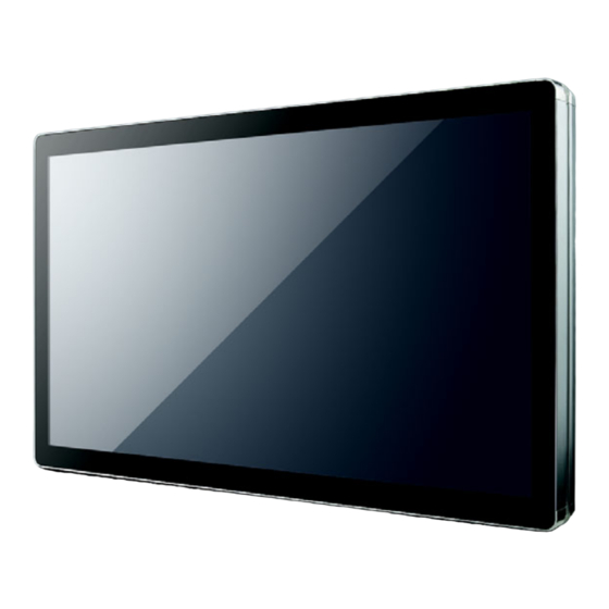
Advantech UTC-520A User Manual
Amd t40e (utc-520a) & intel atom d2550 (utc-520b) processor- based ubiquitous 21.5” lcd touch computer
Hide thumbs
1
2
3
4
5
6
Table Of Contents
7
8
9
10
11
12
13
14
15
16
17
18
19
20
21
22
23
24
25
26
27
28
29
30
31
32
33
34
35
36
37
38
39
40
41
42
43
44
45
46
47
48
49
50
51
52
53
54
55
56
57
58
59
60
61
62
63
64
65
66
67
68
69
70
71
72
73
74
75
76
77
78
79
80
81
82
83
84
85
page
of
85
Go
/
85
Contents
Table of Contents
Bookmarks
Table of Contents
Declaration of Conformity
Packing List
Technical Support and Assistance
Safety Instructions
Table of Contents
Chapter 1 General Information
Introduction
General Specifications
General
Standard PC Functions
VGA Interface
Table 1.1: Internal Graphics Features
Audio Function
LAN Function
Touchscreen (Optional)
Optional Modules
Environment
LCD Specifications
Dimensions
Figure 1.1 Dimensions of UTC-520A/B
Chapter 2 System Setup
A Quick Tour of the UTC-520A/B
Figure 2.1 Front View of UTC-520A/B
Figure 2.2 Rear View of UTC-520A/B
Installation Procedures
Connecting the Power Cord
Connecting the Keyboard or Mouse
Switching on the Power
Figure 2.3 Connect the Power Cord to the DC Inlet
Running the BIOS Setup Program
Installing System Software
Method 1: Ethernet
Method 2: External USB CD-ROM
Installing the Drivers
Chapter 3 Hardware Installation and Upgrading
Introduction
Installing the 2.5" Hard Disk Drive (HDD)
Figure 3.1 Installing Primary 2.5" HDD
Installing the CFAST
Figure 3.2 Installing the Compact Flash Card
Installing the Memory
Figure 3.3 Installing the Memory
Installing the Wireless LAN Card
Chapter 4 Jumper Settings and Connectors
Jumpers and Connectors (UTC-520A)
Jumpers
Connectors
Table 4.1: Connectors
Mechanical
Figure 4.1 Jumper and Connector Layout (Component Side)
Figure 4.2 Jumper and Connector Layout (Solder Side)
Jumpers and Connectors (UTC-520B)
Jumpers
Table 4.2: Jumpers
Connectors
Table 4.3: Connectors
Mechanical
Figure 4.3 Jumper and Connector Layout (Component Side)
Figure 4.4 Jumper and Connector Layout (Solder Side)
Appendix A Pin Assignments
Pin Assignments (UTC-520A)
Pin Assignments (UTC-520B)
UTC-500 Peripherals Series
Installation Guide
Appendix B UTC-500 Peripherals Series
UTC-500 Peripherals Series Installation Guide
Advertisement
Quick Links
Download this manual
User Manual
UTC-520A/B
AMD T40E (UTC-520A) & Intel
Atom D2550 (UTC-520B)
Processor- based Ubiquitous
21.5" LCD Touch Computer
Table of
Contents
Previous
Page
Next
Page
1
2
3
4
5
Advertisement
Table of Contents
Need help?
Do you have a question about the UTC-520A and is the answer not in the manual?
Ask a question
Questions and answers
Related Manuals for Advantech UTC-520A
Touchscreen Advantech UTC-520B User Manual
Amd t40e (utc-520a) & intel atom d2550 (utc-520b) processor- based ubiquitous 21.5” lcd touch computer (85 pages)
Touchscreen Advantech UPOS-M15 Series Startup Manual
(2 pages)
Touchscreen Advantech UTC-320 User Manual
Intel platform processor based ubiquitous touch computer with 21.5” tft lcd (54 pages)
Touchscreen Advantech POC-W242 User Manual
Point-of-care terminal with intel core i7 or i5 processor and a 23.8’’ full hd ips lcd (54 pages)
Touchscreen Advantech TPC-31 User Manual
3.5"/ 5.7" qvga tft lcd ti cortex-a8 touch panel computer (74 pages)
Touchscreen Advantech TPC-1071H User Manual
Touch panel computer with intel atom dual core processor (32 pages)
Touchscreen Advantech HIT-W121 User Manual
(28 pages)
Touchscreen Advantech ProFlat IDP-31156W User Manual
15.6" projected capacitive touch monitor (14 pages)
Touchscreen Advantech IDP31-215W Series User Manual
21.5" wide screen industrial proflat projected capacitive touch monitor (32 pages)
Touchscreen Advantech IDP31-156W Series User Manual
15.6" industrial proflat projected capacitive touch monitor (32 pages)
Touchscreen Advantech IDP31-156WP Series User Manual
15.6" wide screen industrial proflat projected capacitive touch monitor (30 pages)
Touchscreen Advantech CRV-430JP Series User Manual
43" curved touch monitor (22 pages)
Touchscreen Advantech TPC-662G-B1E User Manual
Amd lx800 touch panel computers with 6.4"/5.6" vga tft lcd (78 pages)
Touchscreen Advantech FPM-5151 Series User Manual
15" xga/17" sxga/19" sxga industrial monitor with resistive touchscreen, direct-vga, dv (40 pages)
Touchscreen Advantech ITM-5117 Series User Manual
17" industrial led touch monitor (25 pages)
Touchscreen Advantech TPC-660G User Manual
Amd lx800 touch panel computer with 6.4” vga tft lcd (80 pages)
This manual is also suitable for:
Utc-520b
Utc-520c
Table of Contents
Print
Rename the bookmark
Delete bookmark?
Delete from my manuals?
Login
Sign In
OR
Sign in with Facebook
Sign in with Google
Upload manual
Upload from disk
Upload from URL


Need help?
Do you have a question about the UTC-520A and is the answer not in the manual?
Questions and answers