Table of Contents
Advertisement
Quick Links
Download this manual
See also:
User Manual
Advertisement
Table of Contents

Subscribe to Our Youtube Channel
Related Manuals for Advantech TPC-1071H


Summary of Contents for Advantech TPC-1071H
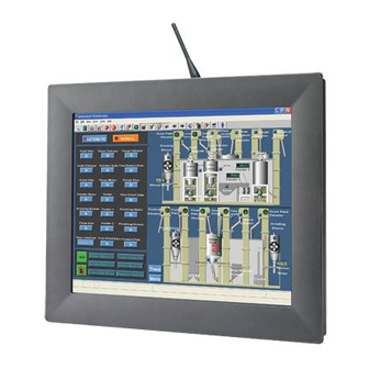
- Page 1 User Manual TPC-1071H/1271H/ 1571H Touch Panel Computer ® With Intel Atom™ Dual Core Processor...
- Page 2 No part of this manual may be reproduced, copied, translated or transmitted in any form or by any means without the prior written permission of Advantech Co., Ltd. Information provided in this manual is intended to be accurate and reliable. How- ever, Advantech Co., Ltd.
- Page 3 Because of Advantech’s high quality-control standards and rigorous testing, most of our customers never need to use our repair service. If an Advantech product is defec- tive, it will be repaired or replaced at no charge during the warranty period. For out- of-warranty repairs, you will be billed according to the cost of replacement materials, service time and freight.
-
Page 4: Declaration Of Conformity
This product has passed the CE test for environmental specifications when shielded cables are used for external wiring. We recommend the use of shielded cables. This kind of cable is available from Advantech. Please contact your local supplier for ordering information. -
Page 5: Safety Instructions
The sound pressure level at the operator's position according to IEC 704-1:1982 is no more than 70 dB (A). DISCLAIMER: This set of instructions is given according to IEC 704-1. Advantech disclaims all responsibility for the accuracy of any statements contained herein. - Page 6 TPC-1071H/1271H/1571H User Manual...
-
Page 7: Table Of Contents
LCD Specifications..................4 Touchscreen Specifications ..............4 Power ......................4 I/O Ports Arrangement ................5 Figure 1.1 TPC-1071H/1271H - I/O Port Arrangement....5 Figure 1.2 TPC-1571H - I/O Port Arrangement ......5 Panel Mounting ..................6 Figure 1.3 Panel Mounting............6 Figure 1.4 Front and Rear Images.......... - Page 8 SW5 & SW6 Termination Resistor Selection......21 DIO Board Pin Assignment and Wiring........... 22 A.4.1 DIO PIN Assignment..............22 A.4.2 Isolated Digital Input -- Dry Contact..........22 A.4.3 Isolated Digital Input -- Wet Contact ........... 23 A.4.4 Isolated Digital Output ..............23 TPC-1071H/1271H/1571H User Manual viii...
-
Page 9: Chapter 1 General Information
Chapter General Information... -
Page 10: Introduction
These products provide isolation 2KV protection for their serial ports. Windows CE Support In addition to the OS support of Windows XP, Advantech offers platform support for WES7 and Windows XP embedded. The optional Windows CE operating system, specifically for Industrial Touch Panel Computers is also available. -
Page 11: Specifications
0 ~ 50°C (32 ~ 122°F) Storage Temperature: – -20 ~ 60°C (-4 ~ 140°F) Humidity: 40°C @ 10~95% relative humidity (non-condensing) Vibration: 2 grms (5 ~ 500 Hz) with CF Card, 1 grm with HDD kit TPC-1071H/1271H/1571H User Manual... -
Page 12: Lcd Specifications
Typical - 24V – Swing Range - 9-32V (the fuse will become an open circuit if the input level exceeds 33V Power Request: 24 V @ 0.71 Amp Full Load: 24 V @ 2.85 Amp TPC-1071H/1271H/1571H User Manual... -
Page 13: I/O Ports Arrangement
I/O Ports Arrangement The arrangement of the I/O ports is shown in in Figure 1.1 and 1.2. Figure 1.1 TPC-1071H/1271H - I/O Port Arrangement Figure 1.2 TPC-1571H - I/O Port Arrangement TPC-1071H/1271H/1571H User Manual... -
Page 14: Panel Mounting
These screws will push the mounting panel and fix the unit. The suggested mounting panel thickness is less than 6 mm (0.236”). Figure 1.3 Panel Mounting Figure 1.4 Front and Rear Images Note! The monitor should be vertically mounted on panels TPC-1071H/1271H/1571H User Manual... -
Page 15: Dimensions And Cutout
Dimensions and Cutout 1.9.1 TPC-1071H Weight: 3kg Dimensions (W x H x D): – 287 x 227 x 72.3 mm (11.29" x 8.94" x 2.84") Cutout: – 279.5 x 219 mm Figure 1.5 TPC-1071H Dimensions TPC-1071H/1271H/1571H User Manual... -
Page 16: Tpc-1271H
1.9.2 TPC-1271H Weight: 4.57kg Dimensions (W x H x D): – 311 x 237 x 73.1 mm (12.24" x 9.33" x 2.88") Cutout: 302 x 228 mm Figure 1.6 TPC-1271H Dimensions TPC-1071H/1271H/1571H User Manual... -
Page 17: Tpc-1571H
1.9.3 TPC-1571H Weight: 5.5kg Dimensions (W x H x D): – 383 x 307 x 78.5 mm (15.08" x 12.09" x 3.09") Cutout: 374.5 x 298.5 mm Figure 1.7 TPC-1571H Dimensions TPC-1071H/1271H/1571H User Manual... - Page 18 TPC-1071H/1271H/1571H User Manual...
-
Page 19: Chapter 2 System Setup
Chapter System Setup... -
Page 20: System Setup
Unpack the TPC package. Check the packing list at the beginning of this manual to make sure all items have been included. Figure 2.1 Unpack the Package Install a CompactFlash card containing Windows CE, Embedded Windows XP or another operating system. TPC-1071H/1271H/1571H User Manual... -
Page 21: Figure 2.2 Install Compactflash Memory Card
CompactFlash memory is hot swappa- ble. Connect the power connector to the 24 V power lines. The power lines can either be of some power adapter or in-house power source. Figure 2.3 Power Connector and Power Lines TPC-1071H/1271H/1571H User Manual... -
Page 22: Figure 2.4 Power Receptor & Button Pin Assignment
Installing the Drivers After installing your system software, you will be able to set up the Ethernet, VGA, and touchscreen functions. All drivers are stored in a DVD entitled “TPC-1071H, TPC-1271H or TPC-1571H” which can be found in your accessory box. - Page 23 Chapter Features in Windows XP Embedded...
-
Page 24: Features In Windows Xp Embedded
Advantech provides a pair of utilities to operate EWF, OSLock andOSUnLock. Please refer the training slide in the folder, file name is "Advantech XPe Add-one.pdf". HORM HORM stands for Hibernate Once Resume Many. In HORM environment, a single hibernation file is used to boot the system repeatedly. -
Page 25: Jumper & Dip Switch Setting List And
Appendix Jumper & Dip Switch Setting List and DIO Pin Assignment and Wiring... -
Page 26: Jumper And Dip Switch Settings
Jumper and DIP Switch Settings If you need to adjust the jumper or DIP switch settings refer to the information below. A.1.1 Jumper and Switch Locations Figure A.1 Jumper and Switch Locations TPC-1071H/1271H/1571H User Manual... -
Page 27: Jumper Settings
+5V is used to supply LCD panel 3-5 & 4-6 +3.3V is used to supply LCD panel* * Default setting A.2.2 JP2 CMOS Clear Select JP2 is used to select CMOS enable/disable Description Enable (Clear CMOS) Disable* * Default setting TPC-1071H/1271H/1571H User Manual... -
Page 28: Dip Switch Settings
Bit 4 Select 6 or 8 bits LVDS input Default settings TPC-1071H TPC-1271H TPC-1571H Bit 1 Bit 2 Bit 3 Bit 4 A.3.3 SW3 FPGA Default settings TPC-1071H TPC-1271H TPC-1571H Bit 1 Bit 2 Bit 3 Bit 4 TPC-1071H/1271H/1571H User Manual... -
Page 29: Sw4 Lcd Resolution Select
SW5 and SW6 are used to select the Termination Resistor (120 ohm) for long dis- tance transmission or device matching Description Bit 1 Termination resistor select Enable Disable Bit 2 Termination resistor select Enable Disable Default Setting TPC-1071H TPC-1271H TPC-1571H Bit 1 Bit 2 TPC-1071H/1271H/1571H User Manual... -
Page 30: Dio Board Pin Assignment And Wiring
DIO Board Pin Assignment and Wiring A.4.1 DIO PIN Assignment A.4.2 Isolated Digital Input -- Dry Contact TPC-1071H/1271H/1571H User Manual... -
Page 31: Isolated Digital Input -- Wet Contact
A.4.3 Isolated Digital Input -- Wet Contact A.4.4 Isolated Digital Output TPC-1071H/1271H/1571H User Manual... - Page 32 No part of this publication may be reproduced in any form or by any means, electronic, photocopying, recording or otherwise, without prior written permis- sion of the publisher. All brand and product names are trademarks or registered trademarks of their respective companies. © Advantech Co., Ltd. 2011...
Need help?
Do you have a question about the TPC-1071H and is the answer not in the manual?
Questions and answers