Sign In
Upload
Manuals
Brands
Omron Manuals
Security Sensors
F3SG-SRA Series
Omron F3SG-SRA Series Manuals
Manuals and User Guides for Omron F3SG-SRA Series. We have
2
Omron F3SG-SRA Series manuals available for free PDF download: User Manual, Instruction Sheet
Omron F3SG-SRA Series User Manual (399 pages)
Brand:
Omron
| Category:
Security Sensors
| Size: 24.68 MB
Table of Contents
Legislation and Standards
3
Terms and Conditions Agreement
5
Terms and Conditions Agreement (Software)
7
Safety Precautions
8
Precautions for Safe Use
14
Precautions for Correct Use
15
Visual Aids
17
Table of Contents
19
Chapter1 Overview And Specifications
29
What Is Included
30
System Components
31
List of Key Features
33
Model Overview
33
List of Key Features
35
LED Indicators on F3SG-SR
36
Ratings and Specifications
40
F3SG-SR Series
40
Intelligent Tap
47
Bluetooth® Communication Unit
48
List of Models
49
List of Models and Response Times
49
List of Models, Current Consumption and Weight
52
Calculation of Response Time of Cascaded Segments
56
Chapter2 System Operation and Functions
57
Combination of Functions
59
Operating States
61
Operating States of F3SG-SR and Intelligent Tap
61
Operating States of Intelligent Tap
62
Mutual Interference Prevention
63
Mutual Interference Prevention of F3SG-SR
63
Optical Synchronization
63
Wired Synchronization
66
PNP/NPN Selection
67
Overview
67
Setting with Intelligent Tap
67
Setting with SD Manager
67
Self-Test
68
Overview
68
Self-Test Details
68
Waveform of Safety Outputs
69
External Test
70
Overview
70
Factory Default Setting
71
Setting with Intelligent Tap
71
Setting with SD Manager
71
Lockout Reset
72
Interlock
73
Over View
73
Factory Default Setting
75
Setting with Intelligent Tap
75
Setting with SD Manager
75
Pre-Reset
76
Overview
76
Factory Default Setting
77
Setting with Intelligent Tap
78
Setting with SD Manager
78
Psdi
79
2-10-1.Overview
79
2-10-2.Factory Default Setting
81
2-10-3.Setting Change Using Intelligent Tap
81
2-10-4.Setting Change Using SD Manager
81
External Device Monitoring (EDM)
82
2-11-1.Overview
82
2-11-2.Factory Default Setting
83
2-11-3.Setting with Intelligent Tap
83
2-11-4.Setting with SD Manager
84
Auxiliary Output
85
2-12-1.Overview
85
2-12-2.Factory Default Setting
86
2-12-3.Setting with Intelligent Tap
86
2-12-4.Setting with SD Manager
87
Muting
89
2-13-1.Overview
89
2-13-2.Standard Muting Mode
91
Overview
91
Installation Example 1 of Standard Muting Mode (Using Two Muting Sensors)
94
2-13-3.Exit-Only Muting Mode
101
Overview
101
Installation Example of Exit-Only Muting Mode
103
2-13-4.Position Detection Muting Mode
106
Overview
106
Installation Example of Position Detection Muting Mode
108
2-13-5.Dynamic Muting
110
2-13-6.Factory Default Setting
111
2-13-7.Setting with Intelligent Tap
111
2-13-8.Setting with SD Manager
111
Override
113
2-14-1.Overview
113
2-14-2.Override at Normal Operation
114
2-14-3.Override Upon Startup
116
2-14-4.Setting with Intelligent Tap
116
2-14-5.Setting with SD Manager
117
Fixed Blanking
118
2-15-1.Overview
118
2-15-2.Factory Default Setting
122
2-15-3.Setting with Intelligent Tap
123
2-15-4.Setting with SD Manager
123
Floating Blanking
124
2-16-1.Overview
124
2-16-2.Factory Default Setting
128
2-16-3.Setting with Intelligent Tap
128
2-16-4.Setting with SD Manager
128
Reduced Resolution
129
2-17-1.Overview
129
2-17-2.Factory Default Setting
130
2-17-3.Setting with Intelligent Tap
130
2-17-4.Setting with SD Manager
131
Warning Zone
132
2-18-1.Overview
132
2-18-2.Factory Default Setting
135
2-18-3.Setting with Intelligent Tap
135
2-18-4.Setting with SD Manager
135
Setting Zone Adjacency Conditions
136
2-19-1.Zone Adjacency Condition
136
2-19-2.Zone Overlap Condition
136
Operating Range Selection
138
2-20-1.Overview
138
2-20-2.Factory Default Setting
139
2-20-3.Setting with Intelligent Tap
139
Response Time Adjustment
140
2-21-1.Overview
140
2-21-2.Factory Default Setting
140
2-21-3.Setting with Intelligent Tap
140
2-21-4.Setting with SD Manager
140
Area Beam Indicator (ABI)
141
2-22-1.Overview
141
2-22-2.Factory Default Setting
142
2-22-3.Setting Change Using Intelligent Tap
142
2-22-4.Setting Change Using SD Manager
142
Designated Beam Output
144
2-23-1.Overview
144
2-23-2.Factory Default Setting
144
2-23-3.Setting with Intelligent Tap
144
2-23-4.Setting with SD Manager
145
Stable Light Threshold Adjustment
146
2-24-1.Overview
146
2-24-2.Factory Default Setting
146
2-24-3.Setting Change Using Intelligent Tap
146
2-24-4.Setting Change Using SD Manager
146
Incident Light/Ambient Light
147
2-25-1.Incident Light Level Information
147
Overview
147
Setting with SD Manager
147
2-25-2.Ambient Light Level Information
147
Maintenance Information
148
2-26-1.Overview
148
2-26-2.Error Log
148
2-26-3.Warning Log
148
2-26-4.Power-ON Time
149
2-26-5.Load Switching Frequency
149
2-26-6.Muting Statistics Information
150
2-26-7.Intelligent Tap Log
150
Operating Status Monitoring
151
2-27-1.Overview
151
2-27-2.Readout Information
151
Instantaneous Block Detection
152
2-28-1.Overview
152
2-28-2.Factory Default Setting
152
2-28-3.Setting Change Using Intelligent Tap
152
2-28-4.Setting Change Using SD Manager
152
Setting Recovery
153
Backup/Restoration
154
2-30-1.Overview
154
IO-Link
155
Chapter3 Setting With Intelligent Tap
157
List of Functions Configurable by Intelligent Tap and Initial Setup Method
158
Functions Configurable by Intelligent Tap
158
Initial Setup Method after Purchase
158
Connection
159
Wiring
160
LED Indicators on Intelligent Tap
161
DIP Switch on Intelligent Tap
162
Backup/Restoration
163
Description of Functions
163
Performing Backup
164
Performing Restoration
166
Various Usage of Backup and Restoration
169
Plug and Work
169
Copy and Paste of Sensor Settings
169
Changing F3SG-SR Configuration to Connect to Intelligent Tap
169
Changing F3SG-Sr's Settings with Intelligent Tap DIP Switch
169
Teach-In (Fix Blanking / Floating Blanking)
170
Setting Fixed Blanking by Teach-In
170
Setting Floating Blanking by Teach-In
174
Connection to SD Manager
178
IO-Link
179
Functional Description
179
Communication Specifications
179
Process Data
179
Service Data
181
Chapter 4 Setting with SD Manager 3
185
Overview and Specifications
188
Overview of Configuration Tool
188
System Environment
189
PC Environment
189
Smartphone/Tablet Environment
189
Connection Method to Use Configuration Tools
190
Connection Patterns of F3SG-SR, Intelligent Tap, and each Device
190
Connection Procedure When Using USB Connector
192
Connection Procedure When Using Bluetooth® Communication Unit (F39-SGBT)
193
Connection Procedure When Using Bluetooth
193
SETTING State of F3SG-SR with SD Manager 3 Connected
197
Basic Operation of SD Manager
198
How to Install/Uninstall SD Manager
198
Downloading SD Manager
198
Installing SD Manager
198
How to Uninstall SD Manager
200
Installing Driver of Intelligent Tap
201
How to Update SD Manager
201
Getting Started, Description on Top Page and each Button, and Shutting down
202
Getting Started
202
Getting Started, Description on Top Page and each Button
202
Description on Top Page and each Button
203
Displaying/Hiding Docked Windows
205
Shutting down
205
Starting SD Manager 3 Offline
206
Creating New Configuration File
206
Reading Configuration from PC
207
Saving New Configuration File to PC
207
Switching Offline to Online
207
Logging In/Logging out
208
Logging in
208
Logging out
210
Password Protection
211
Access Restriction
211
Changing Password
211
Forgot the Password
211
Confirming Lot No. of Intelligent Tap
211
Resetting the Initial Password to "0000
212
Reading/Saving/Writing Configuration of Intelligent Tap185
213
Reading Configuration from Intelligent Tap
213
Saving Configuration of Intelligent Tap in PC
213
Writing Configuration into Intelligent Tap
214
Viewing Current Configuration
216
Safety Distance Calculation
217
Changing Settings with SD Manager
218
Preparing to Change Settings
218
I/O Settings
219
Interlock/External Device Monitoring (EDM)/PSDI
219
Reset Input Time
220
Teach-In Input
221
External Test Input
222
Auxiliary Output/Lamp Setting
223
Auxiliary Output
223
Designated Beam Output
223
Designated Beam Output
225
Area Beam Indicator (ABI)
228
Safety Function Setting
230
Fixed Blanking
230
Monitoring
230
Floating Blanking
233
Muting/Override
235
Pre-Reset
240
Reduced Resolution
241
Warning Zone
242
Psdi
244
Operating State Setting
245
Response Time Change
245
Stable Light Threshold Adjustment
246
Operating Range Selection
247
Setting Initialization
248
Monitoring with SD Manager
249
Monitoring
249
Incident Light/Ambient Light
249
Operating Status Monitoring
250
Muting Statistics Information
252
Maintenance Information
256
Error Log Information
256
Warning Log
258
Intelligent Tap Log
259
Power-On Time/Load Switching Frequency
260
Instantaneous Block Detection Information
262
Basic Operation of SD Manager 3 Mobile APP
263
How to Install/Uninstall SD Manager 3 Mobile APP
263
Installing SD Manager 3 Mobile APP
263
Uninstalling SD Manager 3 Mobile APP
263
How to Update SD Manager 3 Mobile APP
263
Pairing (Connection Verification)
263
Getting Started, Main Screen, Version Confirmation, and Shutting down
265
Getting Started
265
Main Screen
267
Version Information
268
Shutting down
269
Monitoring with SD Manager
270
Incident/Ambient Light Level Monitoring
270
Status Monitoring Information
271
Maintenance Information
273
Chapter5 Wiring And Installation
275
Installation Considerations
278
Detection Zone and Approach
278
Safety Distance
280
Safety Distance Formulas According to ISO 13855/EN ISO 13855
280
Safety Distance Formulas According to ANSI B11.19
284
Distance from Reflective Surfaces
285
F3SG-SR (Type 2 ESPE)
285
Mutual Interference Prevention
286
Dimensions
287
F3SG-SR Series
287
Mounted with Side-Mount Brackets (Intermediate Brackets) (F39-LSGF)
287
Mounted with Side-Mount Brackets
287
Mounted with Adjustable Side-Mount Brackets (Intermediate Brackets) (F39-LSGA)
289
Mounted with Adjustable Side-Mount Brackets
289
Mounted with Adjustable Top/Bottom Brackets (F3SJ, F3SN Adapter) (F39-LSGTB-SJ)
291
And Side-Mount Brackets (Intermediate Brackets) (F39-LSGF)
291
Mounted with Adjustable Top/Bottom Brackets
291
Mounted with Adjustable Top/Bottom Brackets (F3SJ, F3SN Adapter) (F39-LSGTB-SJ)
293
And Adjustable Side-Mount Brackets (Intermediate Brackets) (F39-LSGA)
293
Mounted with Adjustable Top/Bottom Brackets
293
Bracket
295
Side-Mount Bracket (Intermediate Bracket) (F39-LSGF)
295
Adjustable Side-Mount Bracket (Intermediate Bracket) (F39-LSGA, Sold Separately)
295
Adjustable Top/Bottom Bracket (F3SJ, F3SN Adapter) (F39-LSGTB-SJ, Sold Separately)
295
Adjustable Top/Bottom Bracket (F3SG-RA/RE Adapter)
296
Adjustable Top/Bottom Bracket (MS4800, F3SR Adapter)
296
Rately)
296
Intelligent Tap
297
Intelligent Tap Bracket
297
Bluetooth® Communication Unit
299
Spatter Protection Cover
300
Mounting
301
Mounting Method
301
Number of Brackets Required
301
Proper Mounting
302
Proper Mounting Orientation
302
Mounting Procedure
304
Mounting with Side-Mount Brackets (Intermediate Brackets)
304
(F39-Lsgf)
304
Mounting with Adjustable Side-Mount Brackets (Intermediate Brackets) (F39-LSGA)
305
Mounting with Adjustable Top/Bottom Brackets (F3SJ, F3SN Adapter) (F39-LSGTB-SJ)
308
And Side-Mount Brackets (Intermediate Brackets) (F39-LSGF)
308
Mounting with Adjustable Top/Bottom Brackets (F3SJ, F3SN Adapter) (F39-LSGTB-SJ)
312
And Adjustable Side-Mount Brackets (Intermediate Brackets) (F39-LSGA)
312
Beam Alignment Procedure
317
Wiring
318
Wiring Precautions
318
Power Supply Unit
319
Cable Connections
320
Root-Straight Cable
320
Root-Plug Cable for Extended
321
Extended Socket-Straight Cable
322
Extended Plug-Socket Cable
323
Cascading Cable for Extended
325
Side-By-Side Cascading Cable
326
F3SJ-B/A Conversion Cable
327
F3SG-RE Conversion Cable
329
MS48 Conversion Cable
330
Extending Cable Length with Commercially Available Cable
331
Reduced Wiring Connector System with Y-Joint Plug/Socket Connector
332
Easy Wiring Connector System with Reset Switch Connector
333
Functional Earth Connection
335
Cascade Connection
336
Overview
336
Connection Procedure
338
Chapter6 Input/Output Circuit and Applications
341
Input/Output Circuit
342
Entire Circuit Diagram
342
Input Circuit Diagram by Function
343
Wiring Examples (for F3SG-SR)
344
Non-Muting System Wiring Examples
344
Auto Reset Mode with Optical Synchronization and EDM Unused
344
Auto Reset Mode with Wired Synchronization and EDM Unused
345
Auto Reset Mode with Optical Synchronization and EDM Used
346
Manual Reset Mode with EDM
347
Manual Reset Mode with EDM and Y-Joint Plug/Socket Connector
348
Manual Reset Mode with Intelligent Tap
349
Manual Reset Mode with Reset Switch Connector
350
Pre-Reset Mode with EDM Unused
351
Pre-Reset Mode with Reset Switch Connector
352
Single Break with EDM and Intelligent Tap
353
Double Break with EDM
354
Muting System Wiring Examples
355
Standard Muting Mode/Exit-Only Muting Mode
355
Standard Muting Mode/Exit-Only Muting Mode with Y-Joint Plug
356
Standard Muting Mode/Exit-Only Muting Mode with Intelligent Tap
357
Standard Muting Mode/Exit-Only Muting Mode with Reset Switch Connector
358
Connectable Safety Control Units
359
Chapter7 Checklists
361
Pre-Operation Checklists
362
Checklists
362
Installation Condition Check
362
Wiring Check before Power Is Turned on
362
Operation Check While the Machine Is Stopped
363
Checking that Hazardous Parts Stop While the Machine Operates
364
Maintenance Checklists
365
Checklists
365
Inspection at Startup and When Changing Operators
365
Checking that Hazardous Parts Stop While the Machine Operates
366
Items to Inspect Every 6 Months or When Machine Settings Are Changed
366
Chapter8 Appendix
369
Troubleshooting
370
LED Indicators (F3SG-SR)
370
LOCKOUT State
371
Description
371
Troubleshooting
372
Warning
377
Description
377
Troubleshooting
377
Muting Sequence Error Indication
378
Interlock Sequence Error Indication
379
PSDI Sequence Error Indication
380
Troubleshooting for Intelligent Tap
381
Troubleshooting for Bluetooth® Communication Unit
384
Optional Accessories (Sold Separately)
385
Glossary
393
Revision History
397
Advertisement
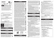
Omron F3SG-SRA Series Instruction Sheet (2 pages)
Brand:
Omron
| Category:
Lighting Equipment
| Size: 0.66 MB
Advertisement
Related Products
Omron F3SG-SRB Series
Omron F3SG-SR Series
Omron F3SG-SR/PG
Omron F3SG-4SRA0280-14-F
Omron F3SG-4SRA0600-14-F
Omron F3SG-4SRA0680-14-F
Omron F3SG-4SRA1440-25
Omron F3SG-4SRB2280-25
Omron F3SG-4SRB0720-45
Omron F3SG-4SRB0760-85
Omron Categories
Blood Pressure Monitor
Controller
Accessories
Switch
Inverter
More Omron Manuals
Login
Sign In
OR
Sign in with Facebook
Sign in with Google
Upload manual
Upload from disk
Upload from URL