Omron E5EC-T Manuals
Manuals and User Guides for Omron E5EC-T. We have 6 Omron E5EC-T manuals available for free PDF download: User Manual, Communications Manual, Manual, Datasheet, Instruction Manual
Omron E5EC-T User Manual (438 pages)
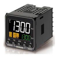
E5xC-T series
Digital Temperature Controllers
Programmable Type
Brand: Omron
|
Category: Temperature Controller
|
Size: 21.38 MB
Table of Contents
Advertisement
Omron E5EC-T Communications Manual (186 pages)
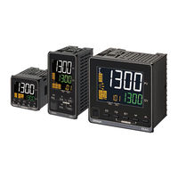
Digital Temperature Controllers Programmable Type
Brand: Omron
|
Category: Temperature Controller
|
Size: 4.5 MB
Table of Contents
Omron E5EC-T Manual (138 pages)
Digital Temperature Controller
Brand: Omron
|
Category: Temperature Controller
|
Size: 42.94 MB
Table of Contents
Advertisement

Omron E5EC-T Datasheet (29 pages)
Programmable Temperature Controller
Brand: Omron
|
Category: Temperature Controller
|
Size: 3 MB
Table of Contents

Omron E5EC-T Instruction Manual (2 pages)
Digital Controller
Brand: Omron
|
Category: Controller
|
Size: 0.91 MB

Omron E5EC-T Instruction Manual (2 pages)
Digital Controller
Brand: Omron
|
Category: Controller
|
Size: 0.79 MB
Advertisement