Sony HDV HVR-1500 Service Manual
Digital hd videocassette recorder with analog input board
Hide thumbs
Also See for HDV HVR-1500:
- Service manual (274 pages) ,
- Operating instructions manual (111 pages) ,
- Brochure & specs (9 pages)

Related Manuals for Sony HDV HVR-1500


Summary of Contents for Sony HDV HVR-1500
- Page 1 DIGITAL HD VIDEOCASSETTE RECORDER HVR-1500 ANALOG INPUT BOARD HVBK-1505 SERVICE MANUAL Volume 1 1st Edition...
- Page 2 Ce manual est destiné uniquement aux personnes compétentes en charge de l’entretien. Afin de réduire les risques de décharge électrique, d’incendie ou de blessure n’effectuer que les réparations indiquées dans le mode d’emploi à moins d’être qualifié pour en effectuer d’autres. Pour toute réparation faire appel à une personne compétente uniquement. HVR-1500...
- Page 3 Klebestreifen ab oder geben Sie die Batterien einzeln in einen Plastikbeutel. Voor de klanten in Nederland Gooi de batterij niet weg maar lever deze in als klein chemisch afval (KCA). For the customers in Taiwan only 1 (P) HVR-1500...
- Page 4 Hävitä käytetty paristo valmistajan ohjeiden Remplacer uniquement avec une batterie du même mukaisesti. type ou d’un type équivalent recommandé par le constructeur. Mettre au rebut les batteries usagées conformément aux instructions du fabricant. 2 (P) HVR-1500...
-
Page 5: Table Of Contents
2-10. Switch Setting on Circuit Boards ......... 2-14 4-3-4. SERVO ADJUST ..........4-24 2-11. Circuit Protection Parts (Fuse/IC Link) ......2-15 4-3-5. TAPE PATH ADJUST ........4-31 2-12. Replacing NV-RAM and Memory Backup Battery ..2-16 4-3-6. ELECTRICAL ADJUST ........4-32 HVR-1500... - Page 6 8-2. Audio Adjustment ............8-2 6-18. MIC Assembly Replacement ........6-51 8-2-1. Audio Output Level Adjustment ......8-2 6-19. MIC Holder Assembly Replacement ......6-55 8-2-2. Audio EE Level Adjustment ......... 8-2 6-20. HC Roller Assembly Replacement ....... 6-57 HVR-1500...
- Page 7 SDI Free-running Adjustment ........8-15 8-5. LCD Adjustment ............8-16 8-5-1. Contrast Adjustment ..........8-16 8-5-2. V-COM Adjustment ..........8-16 8-5-3. Sample Hold Timing Adjustment ....... 8-17 8-5-4. White Balance Adjustment ........8-18 8-6. Adjustment Related Parts Layout Diagram ....8-19 HVR-1500...
-
Page 8: Manual Structure
Purpose of this manual This manual is the Service Manual Volume 1 for the digital HD videocassette recorder HVR-1500, the option board Analog Input Board HVBK-1505. This manual contains the maintenance information of this equipment, and servicing information necessary for parts replacement and adjustments. -
Page 9: Installation
Section 1 Installation Be sure to install the HVR-1500 in location satisfying the required operational environment described below to assure the HVR-1500 superior performance and to maintain the excellent serviceability and accessibility. 1-1. Operating Conditions Good air circulation is essential to prevent internal heat build-up. Place the unit in location with sufficient air circulation. -
Page 10: Power Supply
2 Plug holder (Brown): 3-613-640-01 This unit does not come with a power cord. AC inlet To get a power cord, please contact your local Sony Sales Office/Service Center. . Use the approved Power Cord (3-core mains lead)/ Appliance Connector/Plug with earthing-contacts that... -
Page 11: Supplied Accessories
PDV12CL (Standard size), PDVM12CL (Mini size) 1-5. Matching Connectors/Cables When external cables are connected to the connector on a connector panel during maintenance, the following connectors, cables (or their equivalents) must be used. Connectors on HVR-1500 Side Matching connector/cable Panel indication Designation Sony Part No. -
Page 12: Input/Output Signals Of The Connectors
Pr/R-Y/S-C: 0.286 V p-p (525/59.94) or 0.3 V p-p (625/50), 75 Z (burst level) Monitor video output BNC x 1 (SUPER) CPST: 1.0 V p-p, 75 Z, negative sync BNC x 2 SDI OUT: Serial digital interface format (270 Mbps), SMPTE 259M/ITU-R BT.656 HVR-1500... - Page 13 Controlling Device Controlled Device FRAME GROUND FRAME GROUND RECEIVE A TRANSMIT A TRANSMIT B RECEIVE B TRANSMIT COMMON RECEIVE COMMON PRIORITY IN PRIORITY OUT RECEIVE COMMON TRANSMIT COMMON RECEIVE B TRANSMIT B TRANSMIT A RECEIVE A FRAME GROUND FRAME GROUND HVR-1500...
-
Page 14: Installation Setup And Adjustment
Sets both the REC and PB levels to the normal level. REC : Sets the REC audio level of the channels respectively with the CH-1/2/3/4 knobs. PB : Sets the PB audio level of the channels respectively with the CH-1/2/3/4 knobs. HVR-1500... -
Page 15: Service Overview
Graphics Renderer RT-10 HDV Equalizer CN-1968A HDV/DV Connector Board DDE-22 (HVBK-1505) Analog Video/Audio Input Board AVP-7 Analog Video/Audio Output Board SDI-94 Digital Input/Output Board SSS-12 System/Servo Control CN-2905 Intermediate Board DVP-42 DV Video/Audio Digital Process HPR-20 HDV Video/Audio Digital Process HVR-1500... - Page 16 Board name Circuit function SE-521G Threading Mode Sensor, Tape End Sensor, Loading Motor FG Sensor SE-538G Tension Sensor CN-1863 REC INHIBIT Sensor, MIC Terminal SE-525G Tape Top/End LED SE-522G Tape Top Sensor, Reel Position Sensor DR-428BG Drum/Reel/Capstan Control Board HVR-1500...
- Page 17 Locations of cassette compartment Board name Circuit function CN-2021G Intermediate Board CC-83G Cassette Compartment Mode Detection, Intermediate Board CC-85G Cassette In Detection CC-84G Cassette Type Detection CN-2022G Intermediate Board HVR-1500...
-
Page 18: Location Of Main Mechanical Parts
8 Brake solenoid @- Pinch roller @= HC roller assembly 9 M stop solenoid assembly !/ T brake assembly @[ Drum assembly @] Rail assembly !- MIC assembly @\ Cassette compartment motor assembly != MIC holder assembly ![ T reel motor HVR-1500... -
Page 19: Function And Location Of Sensors
FG output of the sensor is input to the servo circuit and Record proof sensor (common to standard, M and controls the threading speed so that excessive force is not applied to the tape during threading. mini size cassettes) Protects a tape from mis-recording. HVR-1500... - Page 20 2 The sensors PH1, PH2 and PH3 detect the movement of a cassette compartment by their combina- tion. 3 The sensors PH4 and PH5 detect that a mini cassette got inserted. The sensors PH4 and PH6 detect that a M cassette got inserted. The sensors PH4 and PH7 detect that a standard cassette got inserted. HVR-1500...
-
Page 21: Functions Of Cassette
Record proof hole Reel rotation stopper 4 3 2 1 Record proof plug Pin No. Function Equipped with built-in memory Not equipped with built-in memory Detecting tape thickness DATA Detecting tape type (Example: ME/MP) CLOCK Detecting tape application (Example: consumer/professional) HVR-1500... -
Page 22: How To Take Out The Cassette Whose Tape Is Slacked (Manual Eject)
B (red) . Never move the cleaning cloth in the vertical direction against the video head because it may break the head. . Turn the power switch off when cleaning the video head. Skewer Reel table (T) HVR-1500... -
Page 23: Operating The Vtr Without A Cassette Tape
Press the [F|FWD] key. The pinch roller is pressed against the capstan shaft to set the FWD.SEARCH to five-times speed. Press the [REW] key. The pinch roller is pressed against the capstan shaft to set REV.SEARCH to five-times speed. HVR-1500... -
Page 24: Removing/Installing The Cabinets
Be careful not to break or peel off the internal packing. 2. Re-attach the parts in reverse order of the disassem- bling procedure. Holes Top panel B4 x 6 Claws BVTT3 x 6 Bottom plate BVTT3 x 6 B4 x 6 2-10 HVR-1500... -
Page 25: Removal/Installation Of The Front Panel
8. Re-attach the parts in reverse order of the BV3 x 6 disassembling procedure. Harness (AC PSW) Harness B3 x 5 Toothed washer BV3 x 6 Rear panel BVTT3 x 6 Harness (KY-MB) Front panel Flexible card wire CN101 CN500 Claws BVTT3 x 6 2-11 HVR-1500... -
Page 26: Removing/Installing The Cassette Compartment
3. Connect the flexible card wire to the connector (CN1) board on the CC-83G board. Positioning 4. Attach the C cable retainer. hole 5. Attach the top panel. (Refer to Section 2-7-1.) Positioning pins Positioning holes Positioning pins 2-12 HVR-1500... -
Page 27: Function Of Indicators On Circuit Boards
Lights in case of standard signal D203 VCXO H LOCK Off in case of standard signal Lights SDI-94 Board D201 A side (component side) Ref. No. Name Color Description Normal state D201 UNLOCK Lights when SDI output signal is unlock. 2-13 HVR-1500... -
Page 28: Switch Setting On Circuit Boards
Factory setting S401 — Factory use ALL OFF SSS-12 Board S500 S401 A side (component side) Ref. No. Name Description Factory setting S401 — Factory use ALL OFF S500 RESET Push this switch when resetting the system control. — 2-14 HVR-1500... -
Page 29: Circuit Protection Parts (Fuse/Ic Link)
! 1-576-282-21 Replace the components with Sony parts whose part IC link 1.2 A, 72 V numbers appear in the manual published by Sony. If the PS102 (E-3/Side B) ! 1-576-282-21 components are replaced with any parts other than the IC link 1.2 A, 72 V... -
Page 30: Replacing Nv-Ram And Memory Backup Battery
LCD ADJ adjustment value of maintenance menu RP-133 IC501 EEPROM RP adjustment value of maintenance menu SSS-12 IC538 SYSTEM SEL setting data of setup menu (with backup battery) Input/output setting data IC539 EEPROM Setup menu data Menu bank 1-3 data 2-16 HVR-1500... - Page 31 Even if this EEPROM is replaced in the field, no data can Recommended replacement cycle: be initialized. When you need to replace this EEPROM, About 6 years contact your local Sony Sales Office/Service Center. When becoming replacement time, displays (5) Replacing EEPROM (IC300/KY-616 board) an error message to monitor screen and 1.
-
Page 32: Equipment And Fixtures List For Check/Adjustment
Each equipment listed below is available as a standard product. However, it may not be producted now. Equipment Model name Remarks Oscilloscope Tektronix TDS460A Video signal generator Tektronix TSG-130A For 60i mode Tektronix TSG-131A For 50i mode Waveform monitor Tektronix 1750A Audio level meter Agilent Technologies HP3400A Frequency counter Advantest TR5821 2-18 HVR-1500... -
Page 33: Fixtures And Tools
Path tool power supply cable (DJ-500) Tape path adjustment J-6445-160-A Extension board (DJ-516) Extension board for plug-in board J-6445-170-A Extension board (DJ-517) Extension board for KY board J-6445-180-A Extension board (DJ-518) Extension board for switching ragulator J-7120-220-A USB download cable For writing of config ROM/PLD data 2-19 HVR-1500... - Page 34 2 3 4 9 !/ !. @/ @- 2-20 HVR-1500...
-
Page 35: Alignment Tapes
75 % Full Color Bars (B-Y OFF) 21 : 00 Blanking Marker 24 : 00 Line 17 (R-Y OFF) 27 : 00 Line 17 (B-Y OFF) 30 : 00 * Audio levels are _20 dBFS (Reference), except 1 kHz 0 dBFS part. 2-21 HVR-1500... - Page 36 100 % Full Color Bars (B-Y OFF) 21 : 00 Blanking Marker 24 : 00 Line 17 (R-Y OFF) 27 : 00 Line 17 (B-Y OFF) 30 : 00 * Audio levels are _18 dBFS (Reference), except 1 kHz 0 dBFS part. 2-22 HVR-1500...
-
Page 37: Tools For Board Extension
For Plug-in Board Used for extending the plug-in board. Description: Extension board (DJ-516) Sony part No.: J-6445-160-A Extending procedure 1. Turn off the power. 2. Remove the rear panel. (Refer to Section 2-7-4.) 3. Remove the extending plug-in board. - Page 38 For Switching Regulator Used for extending the KY-614 and KY-616 board. Used for extending the switching regulator. Description: Extension board (DJ-517) Description: Extension board (DJ-518) Sony part No.: J-6445-170-A Sony part No.: J-6445-180-A Extending procedure Extending procedure 1. Turn off the power.
-
Page 39: Writing And Rewriting The Pld Internal Data
1. The standard fixture (cable) can be used. 2. The standard software (PLD Download Tool) can be used. . The PLD internal data is controlled in the Sony Database Server under the name Project file (E_xxx_xxx_xx_xx). . The printed circuit board is equipped with the standard connector (EPR connector) to write the PLD internal data. - Page 40 PLD Download Tool software is available. 1. Prepare the Project file. Download the Project file from the Sony Database Server. 2. Turn off the power of this unit. Connect the PC USB port to the EPR connector of the target board using the USB download cable.
-
Page 41: Firmware Update
2-17. Firmware Update The HVR-1500 mounts the CPU for SY and SV on the SSS-12 board and uses flash ROMs for loading this program. Do the following procedure to upgrade the version of the flash ROMs mounted on the board. - Page 42 Normal termination of SV CPU processing. (6) Turn off the power switch of the unit and remove the fixture board. (7) Turn on the power switch of the unit again and confirm the SOFTWARE version on the maintenance menu. (Refer to Section 4-3-8.) 2-28 HVR-1500...
-
Page 43: Version Upgrade From A Pc Through Rs-422
1) Install the version upgrade application software (CHANTA.EXE) on the PC on which Windows 2000 or XP is installed. 2) Download the version upgrade software of CPUs to be upgrade. Connection PORT1 PORT2 HVR-1500 HVR-1500 HPR-20 RS-232C RS-232C REMOTE CN402... - Page 44 7. Press the Exit button, and CHANTA.EXE is ended. 8. Turn off the power of the unit, and disconnect the cable. 9. Turn on the power of the unit. 10. Confirm the version by the SOFWARE VERSION of the MAINTENANCE MENU. (Refer to Section 4-3-8.) 2-30 HVR-1500...
-
Page 45: Internal Video Test Signal
LCD adjustment SD video test signals RP-133 ELECTRICAL ADJUST 4-3-6 PLL F0 EQ AUTO ADJ 100 % Color Bars EQ MANUAL ADJ REC CURRENT FE CHECK SSS-12 LOAD MENU DATA 4-3-1 SERVO ADJUST 4-3-4 75% Color Bars Black Burst 2-31 HVR-1500... -
Page 46: Removing/Installing Flexible Card Wire
The following six types of flexible card wire are used in Raise the portion marked “A” of the connector and release the HVR-1500. the lock. Pull out the flexible card wire. Take utmost care when handling the flexible card wires Insertion method because their life is extremely shortened by folding. - Page 47 Connect the flexible card wire after Flexible card wire checking for the correct side as shown. If the condition side and the insulation side are connected in the wrong direction, the circuit will not operate. Locked status 2-33 HVR-1500...
- Page 48 Be careful that the flexible card wire is not slanted with respect to the connector. Flexible card wire Unlocked status Connector Connector Flexible card wire Locked status Flexible card wire Locked status 2-34 HVR-1500...
-
Page 49: Unleaded Solder
. Do not touch the chip with bare hands. . Do not clean the chip with alcohol or other similar agents. Solders 1 pin Bracket Leads Connector Condensation sensor chip 2-35 HVR-1500... -
Page 51: Error Messages
MENU DATA ’ (MA I NTENANCE MENU) FUNCT I ON. setting of the Setup menu is not changed, the same alarm will appear when the main power is turned on. Display : The alarm is displayed until any key is pressed. HVR-1500... - Page 52 SELECT I ONS OF THE SETUP MENU’S FACTORY USE Operation after detection : None I TEMS HAVE BEEN CHANGED. Display : The alarm is displayed until SET THESE I TEMS TO any key is pressed. FACTORY PRESET VALUES. HVR-1500...
-
Page 53: Error Codes
EJECT mode. ERROR The error code is displayed on the time counter display. TAPE I S BE I NG EJECTED. WA I T UNT I L TH I S I ND I CAT I ON GOES OFF. HVR-1500... - Page 54 The error code is displayed on the time counter display. OF FOLLOW I NG CODE : XX-XXX Perform Section “2-4. How to Take Out the Cassette Whose Tape is Slacked (MANUAL EJECT) ” when a cassette tape cannot be ejected with the emergency EJECT mode. HVR-1500...
-
Page 55: Display Of Previously Detected Error Codes
3-2-1. Display of Previously Detected Error Codes When the HVR-1500 detects an internal abnormality, the error code is memorized in EEPROM. (Exclud- ing error code 9X-XXX) A maximum of 8 error codes detected previously, starting from the latest error code, can be displayed. -
Page 56: Main Codes And Sub Codes
5 : FG detected. 6 : Rotating direction error detected. 7 : Excessive tension detected. 8 : Abnormal current detected. 9 : The full top or full end of a tape cannot be released. A : Retry in progress (Unthreading and re-threading) HVR-1500... - Page 57 IC of the communication counterpart. (The second digit indicates the communica- tion line number and the third digit indicates the CS number.) First digit :CPU (microprocessor) or IC which detects the abnormality..Same as the main code 91 HVR-1500...
-
Page 58: Error Codes
Failed to detect the T reel FG during search. Failed to detect the S and T reel FGs during search. Detected the abnormal direction of S and T reel rotation during search. Detected slack tape during PLAY and REC. HVR-1500... - Page 59 Displayed until operates normally any key is after the error is pressed. solved. Failed to detect the capstan FG by the FG check during Cassette tape Displayed until the cassette tape insertion. will be ejected. next cassette is inserted. HVR-1500...
- Page 60 Detected the abnormal current in the cassette up/down motor. AUTO OFF EJECT Displayed until the (Emergency EJECT) next cassette is Failed to complete the cassette down motion within the inserted. specified time. Failed to complete the cassette up motion within the specified time. 3-10 HVR-1500...
- Page 61 Detected an abnormality of cassette compartment position EJECT sensor. 36-000 Detected an abnormality of fan motor. Only error is displayed. 39-000 Detected an abnormality of cassette top/end sensor LED. STOP PLAY, EJECT 3A-000 Detected an abnormality of tension sensor. AUTO OFF EJECT (Emergency EJECT) 3-11 HVR-1500...
- Page 62 SPCON detected abnormality of external RAM (IC503 on the SSS-12 board). SPCON detected abnormality of internal RAM. SPCON detected abnormality of the communication IC (IC503 on the SSS-12 board) with SY. SPCON detected communication error (IC401 on the SSS-12 board) with SV. 3-12 HVR-1500...
- Page 63 Track pair communication error between SPCON and A1R Rear. Communication error between SPCON and AIF-INDI. Communication error between SPCON and ACTL. Communication error between SPCON and REC-DSP. Communication error between SPCON and PB-DSP. Communication error between SPCON and OUT-DSP. 3-13 HVR-1500...
-
Page 64: Possible Causes Of Errors
↓ When a cassette compartment is lock after it is exchanged, the trouble is caused by the cassette compartment. Otherwise the trouble is caused by cassette compartment the defective drive circuit. DR-428BG board 3-14 HVR-1500... - Page 65 Check the pinch roller. DR-428BG board, pinch solenoid against capstan. Pinch roller must be pressed against the capstan . Pinch roller has mechanical defect. shaft correctly. . Pinch solenoid is open. . Pinch solenoid drive IC is defective. 3-15 HVR-1500...
-
Page 67: Maintenance Menu
REEL BRAKE (>>Brake) M PLUNGER (>>M Plunger) HEAD CLEANER (>>H.Cleaner) SERVO ADJUST (SV Adjust) S/T-REEL & CAPSTAN (>Reel&Cap.) S-REEL ONLY (>S-Reel) T-REEL ONLY (>T-Reel) CAPSTAN ONLY (>Capstan) TENSION (>Tension) TAPE PATH ADJUST (TP Adjust) TRACKING ADJUST (>Tracking) RF SWITCHING POSITION (>Switching) HVR-1500... - Page 68 SY MEMORY DISPLAY (>> SY MEM.) SV MEMORY DISPLAY (>> SV MEM.) SP MEMORY DISPLAY (>> SP MEM.) KY MEMORY DISPLAY (>> KY MEM.) MO MEMORY DIAPLAY (>> MO MEM.) CM DISPLAY (>> CM DISP.) DATA DISPLAY (>Data Check) SP DATA DISPLAY (>>SP DATA) HVR-1500...
-
Page 69: How To Operate Maintenance Menu
4-2-2. How to Enter the Maintenance Menu 1. While pressing the 7 key, press the [MENU] key. The HVR-1500 enters the maintenance menu. The maintenance menu appears on the LCD and video monitor. -
Page 70: Contents Of Maintenance Menu
5. When an item is selected, press the 8 key. The contents of the selected item appear. 6. Press the 7 key to exit MENU DATA CONTROL and return to the main menu. 7. Press the [MENU] key to exit the maintenance menu. HVR-1500... - Page 71 EEPROM in the DR-428BG board. . When the SETUP MENU is upgraded by ROM’s version upgrade, an alarm message appears after the ROM is replaced. Either initialize the SETUP MENU or execute “LOAD MENU DATA” when the alarm appears. HVR-1500...
- Page 72 Confirm that [COMPLETE] appears and data saving is complete. In the case of trouble : Loading of the data will not start if SETUP MENU data has not been saved or the saved SETUP MENU data contains an error. HVR-1500...
-
Page 73: Edit Check
5. When an item is selected, press the 8 key. The contents of the selected item appear. 6. Press the 7 key to exit EDIT CHECK and return to the main menu. 7. Press the [MENU] key to exit the maintenance menu. HVR-1500... - Page 74 Pressing the [REC] and [PLAY] keys simultaneously enters the ASSEMBLE mode. When the REC MODE of the AUDIO CONTROL is set to 4 channel, A1 is assigned to CH-1 and CH-2, and A2 is assigned to CH-3 and CH-4. HVR-1500...
-
Page 75: Servo Check
10. To check other menus and submenus, repeat steps 4 to 9. 11. Press the [MENU] key to exit the maintenance menu. If the [MENU] key is pressed while the check is in progress, the check operation is forcibly ended and the display returns to the main menu. HVR-1500... - Page 76 The respective items of “SENSOR CHECK” are described below : 1 CASS-COMPARTMENT Checks the respective switches of the cassette compartment. SW/Sensor Applicable board CC-85G CC-84G CC-84G board CC-85G board 1. Execute the CASS-COMPARTMENT. 2. Confirm that the sensors are all OFF with no cassette inserted. 4-10 HVR-1500...
- Page 77 5. Insert the standard cassette and confirm that the status of the sensor is the monitor display shown right. 6. Insert the M-ADPT (Cassette adaptor for DVCPRO) and confirm that the status of the sensor is the monitor display shown right. * _ _ : not care 4-11 HVR-1500...
- Page 78 [OFF] on the monitor display. In the case of trouble : If the display does not change check whether the tape-top sensor or the tape-end sensor itself is defective. Check also the tape-top/tape-end sensor circuit (DR-428BG, SE- 521G/522G board). 4-12 HVR-1500...
- Page 79 30 minutes to detect [DRY]. In the case of trouble : If the display does not change from DRY to WET!, check whether the HUMID sensor itself is defective. Check also the HUMID sensor detection circuit (DR-428BG board). 4-13 HVR-1500...
- Page 80 2. Confirm the monitor display is as shown right. 3. Press the REC INHIBIT switch. Confirm that ON is displayed on the monitor display. In the case of trouble : If OFF is not displayed, check the sensor on the MIC arm. 4-14 HVR-1500...
- Page 81 If the brake solenoid does not emit the operating sound and the T reel motor does not rotate in the specified direction even though pressing the 9, 0 keys, check the T reel motor assembly and reel motor driver circuit (SSS-12 board and DR-428BG board). 4-15 HVR-1500...
- Page 82 SSS-12 board. Check also the DR-428BG board (the driver circuit and the threading FG amplifier circuit) and the SE-521G board (the sensor). 4-16 HVR-1500...
- Page 83 In the case of trouble : If the monitor display does not change, check the cassette compartment motor, the SSS-12 board (the sensor input circuit) and the CC-83G board (the sensor). 4-17 HVR-1500...
- Page 84 Confirm that [REVERSE ... OK] appears on the monitor display. In the case of trouble : If the monitor display does not change, check the capstan motor and the capstan motor driver circuits (the SSS-12 board, DR- 428BG board) 4-18 HVR-1500...
- Page 85 PG : [EXIST] In the case of trouble : If the monitor display does not change, check the drum motor, the DR-428BG board (the drum motor driver circuit, the drum FG amp circuit and the drum PG amp circuit). 4-19 HVR-1500...
- Page 86 If the reel table does not move or the monitor display does not change, check the reel position motor, the reel MINI/M/STD position sensor (the SE-522G and DR-428BG boards) and reel position motor driver circuit (the SSS-12 and DR-428BG boards). 4-20 HVR-1500...
- Page 87 Doing so, the monitor display returns to the main menu. In the case of trouble : If the pinch solenoid does not operate, check the pinch solenoid and the driver circuit (the DR-428BG board). 4-21 HVR-1500...
- Page 88 3. Press the [MENU] key to release the M plunger solenoid. Doing so, the monitor display returns to the main menu. In the case of trouble : If the M plunger solenoid does not operate, check the M plunger solenoid and its driver circuit (the DR-428BG board). 4-22 HVR-1500...
- Page 89 3. Press the [MENU] key. Doing so, the monitor display returns to the main menu. In the case of trouble: If the HEAD CLEANER solenoid does not operate, check the HEAD CLEANER plunger solenoid and its driver circuit (the DR- 428BG board). 4-23 HVR-1500...
-
Page 90: Servo Adjust
8. To check other menus and submenus, repeat steps 4 to 7. 9. Press the [MENU] key to exit the maintenance menu. If the [MENU] key is pressed while the adjustment is in progress, the adjustment operation is forcibly ended and the display returns to the main menu. 4-24 HVR-1500... - Page 91 S REEL OFFSET/FRICTION S REEL TORQUE In the case of trouble : When “ADJUST INCOMPLETE” appears on the monitor display, check the SSS-12 and DR-428BG boards (the reel FG amplifier circuit, the reel motor driver circuit) and the S-reel motor. 4-25 HVR-1500...
- Page 92 Adjustment item CAPSTAN FG DUTY In the case of trouble : When “ADJUST INCOMPLETE” appears on monitor display, check the SSS-12 and DR-428BG boards (the capstan motor driver circuit, the capstan FG amplifier circuit) and the capstan motor. 4-26 HVR-1500...
- Page 93 3. Enter “MAINTENANCE MENU” and select “TENSION” from “SERVO ADJUST” using the 9, 0 keys. 4. Press the 8 key to move to the next display. 5. When the display appears, press the SET (YES) key to start the adjustment. 4-27 HVR-1500...
- Page 94 Press the [STOP] key. 8. Keep pressing the 9, 0 keys until the DV torque cassette reading agrees with the specification value on display. 9. When adjustment is completed, press the 8 key. Specification is as indicated on the display. 4-28 HVR-1500...
- Page 95 10. The display changes as shown in the right, and the HVR-1500 enters the tension regulator magnet position check mode. 11. If the check is completed unsatisfactorily, the display changes as shown in the right. 12. Replace the tension regulator assembly in accordance with message on the display.
- Page 96 21. Press the [EJECT] key and remove the DV torque cassette. 22. Confirm that the message “COMPLETE” appears on the display. Press the [EJECT] key to return to the ADJUST menu. When adjustment is complete, attach the cassette compartment. 4-30 HVR-1500...
-
Page 97: Tape Path Adjust
4-3-5. TAPE PATH ADJUST Executes the adjustment of the tape path. (1) TRACKING ADJUST For adjustment of “TRACKING ADJUST”, refer to Section 7-2. (2) RF SWITCHING POSITION For adjustment of “RF SWITCHING POSITION”, refer to Section 7-3. 4-31 HVR-1500... -
Page 98: Electrical Adjust
“ELECTRICAL ADJUST” is selected and its lower layer submenu appears. 4. Move the cursor displayed with a white background to a desired item using the 9, 0 keys. 5. Press the 8 key to select the desired item. 4-32 HVR-1500... - Page 99 3. Press the 7 key to return to the ADJUST menu. 4. Press the [MENU] key to exit the maintenance menu. In the case of trouble : If “INCOMPLETE” appears on the monitor display, check the RP-133 board (the PLL circuit). 4-33 HVR-1500...
- Page 100 If “INCOMPLETE” is displayed on the monitor ; 1 Send the small length of the tape forward and repeat step 2 again. 2 If “INCOMPLETE” is still displayed after performing 1, check the RP-133 board (the EQ circuit). 4-34 HVR-1500...
- Page 101 2 If “INCOMPLETE” is still displayed after performing 1, check the RP-133 board (the EQ circuit). 3 DVCPRO When the adjustment EQ AUTO ADJ of the DVCAM is executed, the exactly same adjustment data is automatically reflected. Therefore, do not execute this adjustment in the DVCPRO. 4-35 HVR-1500...
- Page 102 Main E → Main O In the case of DV : Main E → Main O 7. Confirm that the DATA on the screen is 0000* through 000F*. If press the SET (YES) key during confirmation, perform the EQ AUTO adjustment. 4-36 HVR-1500...
- Page 103 4. REC CURRENT 1. Selected the REC CURRENT. 2. Press the 9, 0 keys and the 7, 8 keys to adjust the data to “B0”. 3. Press the SET (YES) key to save the data. 4-37 HVR-1500...
- Page 104 (i.e., erase) the recorded segment for about 30 seconds. 7. Playback the segment recorded (erased) in step 6. and confirm that the waveform level is 30% or less. Only the video sub-code is erased. B < A x 0.3 4-38 HVR-1500...
- Page 105 Section “4-3-6. Electrical Adjust.” 1. PLL F0 2. EQ AUTO ADJ 4. REC CURRENT 9. AVP BOARD ADJ For adjustment of “AVP BOARD ADJ”, refer to Section 8-3. 10. LCD ADJ For adjustment of “LCD ADJ”, refer to Section 8-5. 4-39 HVR-1500...
-
Page 106: Service Support
6. After completing the check, press the [MENU] key to return to the main menu. 7. To check other menus and submenus, repeat steps 4 to 6. 8. Press the [MENU] key to exit the maintenance menu. 4-40 HVR-1500... - Page 107 2. MANUAL EJECT For the operating procedure of how to take out a tape when the EJECT is inoperable, refer to Section 2-4. 3. DIAGNOSTICS CONTROL 1 CLEAR ERROR LOG Clears the error history from the ERROR LOG. 4-41 HVR-1500...
-
Page 108: Others
6. After completing the check, press the [MENU] key to return to the main menu. 7. To check other menus and submenus, repeat steps 4 to 6. 8. Press the [MENU] key to exit the maintenance menu. 4-42 HVR-1500... - Page 109 SDI: IC601 on the SDI-94 board. The message NONE appears for the XVIC when the option HVBK-1505 is not installed in the HVR-1500. Contents which are shown in the time counter display can be changed using the 9, 0 keys.
- Page 110 AUDIO VAR: Operation checks of the VARIABLE switch. KEY INPUT: Operation checks of the keys in the front panel. Press the [MENU] key to return to the maintenance menu. (4) MEMORY DISPLAY Factory use only. (5) DATA DISPLAY Factory use only. 4-44 HVR-1500...
-
Page 111: Periodic Inspection And Maintenance
A-1156-785-A Tension regulator G assembly Guide roller S4 A-8279-399-D TG-1 arm assembly Tape running surface —— —— —— (including tape cleaner) Head cleaner X-3605-665-3 HC roller assembly Others Cassette memory terminal A-8323-659-C MIC holder assembly T2 : DRUM ROTATION HVR-1500... -
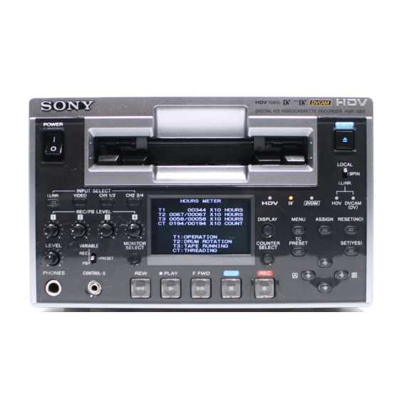
Page 112: Hours Meter
(except for the still mode during search) CT : THREADING Numbers of times of threading and unthreading Example : The following display indicates that the accumulated hours of drum rotation at the threaded-end position is 1500 hours. HVR-1500... -
Page 113: Displaying Hours Meter Information
8 key is kept pressed. When the hours meter value becomes larger and exceeds the limit of display, “ ______ ” will appear. 7. Press the [MENU] key again to return to the original mode. [Counter display area] HVR-1500... -
Page 114: How To Reset Hours Meter
If the main power is turned off while the message appears, the memory will not be reset correctly. Do not turn off the main power while the display appears. 8. Set the switch S401-1 on the SSS-12 board to OFF. HVR-1500... -
Page 115: Cleaning
. Never move the cleaning cloth in vertical direction with respect to the drum rotation (up and down with respect to the drum) during cleaning. . After cleaning, wipe off moisture using a dry cleaning cloth. . Turn off the main power before cleaning a unit. HVR-1500... -
Page 116: Cassette Compartment Entrance Cleaning
5-3-5. Cassette Guide Assembly Cleaning Clean the rear block of the cassette guide assembly with a cleaning cloth moistened with a cleaning fluid. Rear block of the cassette guide assembly Cassette guide area (Cleaning) Section view of the cassette insertion slot HVR-1500... -
Page 117: Replacement Of Mechanical Parts
HVR-1500 not so far as specified. (Refer to Section 2-8.) . When the connector of the cassette compartment is removed, the protection circuit starts functioning. Refer to section “2-6. Operating the VTR without a Cassette Tape.” to operate the HVR-1500 without the cassette compartment. -
Page 118: Tightening Torque And Handling Of Washers
For M2 screw : 0.2 N.m (2.0 kgf.cm) The HVR-1500 uses many small screws that easily fall inside the machine when removing and re-assembling parts. To avoid this risk, magnetize the screwdriver bit slightly enough to prevent small screws from falling into the machine. -
Page 119: Drum Replacement
4. Remove the bottom plate. (Refer to Section 2-7-2.) 5. Remove the cassette compartment assembly. (Refer to Section 2-8.) Tool . Cleaning cloth : 3-184-527-01 . Cleaning fluid : 9-919-573-01 . Torque screwdriver bit (for M1.4) : J-6325-110-A . Torque screwdriver (for 3 kgf.cm) : J-6325-400-A HVR-1500... - Page 120 (2) Remove the flexible card wire connected to the connector (CN102) on the RP-133 board. When disconnecting the connector, take extra care not to injure your hands with the chassis, etc. CN102 RP-133 board CN12 DR-428BG board HVR-1500...
- Page 121 Cleaning (4) While moving the drum assembly in the Hole direction of the arrow (counterclockwise direction), tighten the three precision screws in the order of a, b, c. Tightening torque : 0.1 N.m {1 kgf.cm} Positioning pin HVR-1500...
- Page 122 Positioning hole (CN11) on the DR-428BG board. CN11 . Use care not to contact the head cleaner assembly with the tape running surface on the drum. Positioning pin . Do avoid touching the HC roller assembly with bave hands. HVR-1500...
- Page 123 Adjustment after Replacement 7. Tape path adjustment (Refer to Section 7-2.) 8. RF switching position adjustment (Refer to Section 7-3.) 9. EQ adjustment (Refer to Section 4-3-6.) CN102 RP-133 board CN12 DR-428BG board HVR-1500...
-
Page 124: Brake Solenoid Replacement
. Torque screwdriver’s bit (for M1.4) : J-6325-110-A . Torque screwdriver’s bit (for M2) : J-6325-380-A . Torque screwdriver (for 3 kgf.cm) : J-6325-400-A . Washer extracting fixture (A) : J-6082-234-A . Washer mounting fixture Ø1.5 : J-6082-231-A . Tweezers HVR-1500... - Page 125 (2) Pull out the harness of the solenoid from the P1.4 x 3.5 square hole in the left side of the chassis with Brake assembly the brake assembly lifted up. Precision screw P1.4 x 3.5 Harness Chassis Hole CN15 HVR-1500...
- Page 126 Tightening Torque : 0.5 N.m {5 kgf.cm} (8) Reattach the brake slider assembly to the brake base assembly with a new stop washer. Slide shaft 6-10 HVR-1500...
- Page 127 (2) Following the pop-up menu in the mainte- nance menu, enter SERVO CHECK, Reference pins PLUNGER CHECK, REEL BRAKE in order and select REEL BRAKE. (3) Check that the brake solenoid ON/OFF switches smoothly by presing the 9, 0 keys. 6-11 HVR-1500...
-
Page 128: Pinch Roller Replacement
4. Remove the cassette compartment. (Refer to Section 2-8.) Tools . Washer extracting fixture (A) : J-6082-234-A . Washer mounting fixture Ø1.5 : J-6082-231-A . Cleaning cloth : 3-184-527-01 . Cleaning fluid : 9-919-573-01 . Grease (SG-941) : 7-662-001-39 . Tweezers 6-12 HVR-1500... - Page 129 MD chassis, while fitting the slotted hole in the pinch limiter assembly on the shaft on the pinch solenoid assembly, and fix it with a new stop washer (1.5). Adjustment after Replacement 3. Checking the tape path adjustment (Refer to Section 7-4.) 6-13 HVR-1500...
-
Page 130: Elevator Cam Replacement
4. Remove the cassette compartment. (Refer to Section 2-8.) Tools . Washer extracting fixture (A) : J-6082-234-A . Washer mounting fixture Ø1.5 : J-6082-231-A . Cleaning cloth : 3-184-527-01 . Cleaning fluid : 9-919-573-01 . Grease (SGL-941) : 7-662-001-39 . Tweezers 6-14 HVR-1500... - Page 131 (7) Fit the compressed coil spring on the shaft. Intermittent portion No.7 gear 3. Reattaching the pinch limiter assembly Reattach the pinch limiter assembly. (Refer to Section 6-4.) Adjustment after Replacement 4. Checking the tape path adjustment. (Refer to Section 7-4.) 6-15 HVR-1500...
-
Page 132: Pinch Solenoid Assembly Replacement
4. Remove the cassette compartment. (Refer to Section 2-8.) Tools . Torque screwdriver’s bit (for M1.4) : J-6325-110-A . Torque screwdriver (for 3 kgf.cm) : J-6325-400-A . Washer extracting fixture (A) : J-6082-234-A . Washer mounting fixture Ø1.5 : J-6082-231-A . Tweezers 6-16 HVR-1500... - Page 133 Reconnect the harness to the connector (CN20) on the DR-428BG board with tweezers. 5. Reattaching the pinch limiter assembly Reattach the pinch limiter assembly. (Refer to Section 6-4.) Adjustment after Replacement 6. Checking the tape path adjustment (Refer to Section 7-4.) 6-17 HVR-1500...
-
Page 134: Reel Motor (T) Assembly Replacement
1. After setting the standard cassette position, set the unit to the unthreading end status. 2. Power off the unit. 3. Remove the top panel. (Refer to Section 2-7-1.) 4. Remove the cassette compartment. (Refer to Section 2-8.) 6-18 HVR-1500... - Page 135 S/T reel tables to the standard cassette position. (Refer to Section 6-18.) 3. Removing the L push plate Precision screws Remove the two precision screws to remove the L P1.4 x 3.5 push plate. L push plate 6-19 HVR-1500...
- Page 136 (b) P1.4 x 3.5 (1) Remove the precision screw (a) with the T- T drawer arm assembly drawer arm assembly drawn lightly in the arrow direction. (2) Remove the precision screw (b) and remove the RMP (T1) retainer assembly. 6-20 HVR-1500...
- Page 137 (7) Insert the flexible card wire in the square hole in the MD chassis. (8) Tighten the screw a and next b to reattach the slide shaft. Tightening Torque : 0.1 N.m {1 kgf.cm} RS plate assembly Cleaning Square hole 6-21 HVR-1500...
- Page 138 Check the S/T reel tables move smoothly by turning the reel shift motor gear by a skewer. Adjustment after Replacement 12. T-REEL ONLY adjustment (Refer to Section 4-3-4.) Protrusion 13. TENSION adjustment (Refer to Section 4-3-4.) 14. Tape path adjustment (Refer to Section 7-2.) 6-22 HVR-1500...
-
Page 139: Reel Motor (S) Assembly Replacement
4. Remove the cassette compartment. (Refer to Section 2-8.) Tools . Torque screwdriver’s bit (for M1.4) : J-6325-110-A . Torque screwdriver’s bit (for M2) : J-6325-380-A . Torque screwdriver (for 3 kgf.cm) : J-6325-400-A . Cleaning cloth : 3-184-527-01 . Cleaning fluid : 9-919-573-01 6-23 HVR-1500... - Page 140 (2) Remove the precision screw (b), then remove the RMP (S1) retainer assembly. Screw (a) Precision screw (a) P1.4 x 3.5 Precision screw (b) P1.4 x 3.5 RMP retainer (S1) assembly 6-24 HVR-1500...
- Page 141 (7) Insert the flexible card wire in the square hole Slot in the MD chassis. RS plate (8) Tighten the screw a and next b to reattach assembly Cleaning the slide shaft. MD chassis Tightening Torque : 0.1 N.m {1 kgf.cm} 6-25 HVR-1500...
- Page 142 Check the S/T reel tables move smoothly by turning the reel shift motor gear by a skewer. Adjustment after Replacement 8. S-REEL ONLY alignment (Refer to Section 4-3-4.) 9. TENSION alignment (Refer to Section 4-3-4.) 10. Tape path adjustment (Refer to Section 7-2.) 6-26 HVR-1500...
-
Page 143: M Stop Solenoid Replacement
4. Remove the DR-428BG board. (Refer to Section 6-26-5.) Tools . Torque screwdriver’s bit (for M1.4) : J-6325-110-A . Torque screwdriver bit (for M2) : J-6325-380-A . Torque screwdriver (for 3 kgf.cm) : J-6325-400-A . Locking compound (Three bond-1401B) : 7-432-114-11 6-27 HVR-1500... - Page 144 M stop solenoid (3) Insert the pin of the iron core pin into the two Notches notches of the M plunger plate assembly and Compression coil spring fix it tentatively with the two precision screws. Iron core Hole Pins 6-28 HVR-1500...
- Page 145 After tightening the screw, apply the locking Groove of MS silder compound to the two screws. Tightening torque : 0.2 N.m {2 kgf.cm} 1.5 ± 0.1 mm Specification : Fig. 2 MS slider Screw B fixed tentatively M stopper drive plate assembly 6-29 HVR-1500...
- Page 146 MIC drive (M) assembly move smoothly “b” when the iron core of the solenoid is moved in the direction of energizing (pulled in). Shaft “c” M stop drive plate Slot assembly Slot Precision screws P1.4 x 3.5 M stopper (S) assembly 6-30 HVR-1500...
-
Page 147: S Tension Regulator Assembly Replacement
4. Remove the cassette compartment. (Refer to Section 2-8.) Tools . Torque driver’s bit (for M1.4) : J-6325-110-A . Torque driver (for 3 kgf.cm) : J-6325-400-A . Cleaning cloth : 3-184-527-01 . Cleaning fluid : 9-919-573-01 . Tweezers 6-31 HVR-1500... - Page 148 The column pushes the spring under unthreading end status. Unless satisfy these conditions, perform the Post of No.3 gear Positioning pin step (2) and after. (7) Turn the manual eject cover counterclock- wise to bring to the unthreading end position. 6-32 HVR-1500...
- Page 149 Wipe the tape guides of the S tension regulator and the TG1 arm assemblies with a cleaning cloth moistened with cleaning fluid. Adjustment after Replacement 9. TENSION adjustment (Refer to Section 4-3-4.) 10. Tape path adjustment (Refer to Section 7-2.) 6-33 HVR-1500...
-
Page 150: T Drawer Arm Assembly Replacement
1. Let the unit into the unthreading position. 2. Power off the unit. 3. Remove the top panel. (Refer to Section 2-7-1.) 4. Remove the cassette compartment. (Refer to Section 2-8.) Tools . Cleaning cloth : 3-184-527-01 . Cleaning fluid : 9-919-573-01 . Tweezers 6-34 HVR-1500... - Page 151 Wipe the tape guide on the T drawer arm assem- Sleeve Hole bly with a cleaning cloth moistened with cleaning No.6 gear fluid. T gear Adjustment after Cleaning 5. Checking the tape path adjustment (Refer to Section 7-4.) Shaft Groove MD chassis T spring Grease T gear 6-35 HVR-1500...
-
Page 152: Tg1 Arm Assembly Replacement
3. Remove the top panel. (Refer to Section 2-7-1.) 4. Remove the cassette compartment. (Refer to Section 2-8.) Tools . Torque screwdriver’s bit (for M1.4) : J-6325-110-A . Torque screwdriver (for 3 kgf.cm) : J-6325-400-A . Cleaning cloth : 3-184-527-01 . Cleaning fluid : 9-919-573-01 6-36 HVR-1500... - Page 153 2. Cleaning the tape guide Wipe the tape guide on the TG1 arm assembly with a cleaning cloth moistened with cleaning fluid. Adjustment after Replacement 3. TENSION adjustment (Refer to Section 4-3-4.) 4. Checking the tape path adjustment (Refer to Section 7-4.) 6-37 HVR-1500...
-
Page 154: Tg8 Arm Assembly Replacement
. Torque screwdriver’s bit (for M1.4) : J-6325-110-A . Torque screwdriver (for 3 kgf.cm) : J-6325-400-A . Washer extracting fixture (A) : J-6082-234-A . Washer mounting fixture Ø1.5 : J-6082-231-A . Cleaning cloth : 3-184-527-01 . Cleaning fluid : 9-919-573-01 . Tweezers 6-38 HVR-1500... - Page 155 2. Cleaning the tape guide Wipe the tape guide on the TG8 arm assembly with a cleaning cloth moistened with cleaning fluid. Adjustment after Replacement 3. Adjustment after replacement Checking the tape path adjustment (Refer to Section 7-4.) 6-39 HVR-1500...
-
Page 156: Rail Assembly Replacement
4. Remove the cassette compartment. (Refer to Section 2-8.) Tools . Torque screwdriver’s bit (for M1.4) : J-6325-110-A . Torque screwdriver (for 3 kgf.cm) : J-6325-400-A . Cleaning cloth : 3-184-527-01 . Cleaning fluid : 9-919-573-01 . Tweezers 6-40 HVR-1500... - Page 157 6. Removing the rail assembly (1) Disconnect the flexible card wire from the connector (CN2) on the SE-522G board. Use extreme care not to fold and not to scratch the flexible card wire when discon- necting. SE-522G board Flexible card wire 6-41 HVR-1500...
- Page 158 Use extreme care not to scratch the drum and the tape guide when removing. Also great care should be taken; not to fold and not to scratch the flexible card wire of the LED holder assembly when disconnecting. Rail assembly Flexible card wire 6-42 HVR-1500...
- Page 159 Shuttle (R) assembly Gear (5) Unlock each two claws located on the left, right and middle side of the LED holder assembly with tweezers, and remove the LED holder assembly from the rail assembly. Claw Claw LED holder assembly 6-43 HVR-1500...
- Page 160 Shuttle (L) assembly far as it will go, and align the positioning hole of the shuttle (L) assembly with the positioning hole of the rail assembly. Rail assembly Gear Positioning hole Shuttle (L) assembly Rail plate Positioning hole 6-44 HVR-1500...
- Page 161 . T drawer arm assembly . S tension regulator assembly . Shuttle (R) assembly . Shuttle (L) assembly Adjustment after Replacement 14. TENSION adjustment (Refer to Section 4-3-4.) 15. Tape path adjustment (Refer to Section 7-2.) 6-45 HVR-1500...
-
Page 162: Capstan Motor Replacement
4. Remove the bottom panel. (Refer to Section 2-7-2.) 5. Remove the cassette compartment. (Refer to Section 2-8.) Tools . Torque screwdriver’s bit (for M1.4) : J-6325-110-A . Torque screwdriver (for 3 kgf.cm) : J-6325-400-A . Cleaning cloth : 3-184-527-01 . Cleaning fluid : 9-919-573-01 6-46 HVR-1500... - Page 163 4. Cleaning the Capstan shaft Wipe the capstan shaft with a cleaning cloth moistened with cleaning fluid. Adjustment after Replacement 5. CAPSTAN ONLY adjustment (Refer to Section 4-3-4.) 6. Checking the tape path adjustment (Refer to Section 7-4.) 6-47 HVR-1500...
-
Page 164: Loading Motor Replacement
(3) Fix the loading motor assembly with the two precision screws. Tightening Torque : 0.1 N.m {1 kgf.cm} Motor gear 3. Reconnecting the connector Reconnect the harness to the connector (CN10) on the DR-428BG board with tweezers. FG gear assembly 6-48 HVR-1500... -
Page 165: Reel Shift Motor Assembly Replacement
. Torque screwdriver’s bit (for M1.4) : J-6325-110-A . Torque screwdriver (for 3 kgf.cm) : J-6325-400-A . Washer extracting fixture (A) : J-6082-234-A . Washer mounting fixture Ø1.5 : J-6082-231-A . Cleaning cloth : 3-184-527-01 . Cleaning fluid : 9-919-573-01 . Tweezers 6-49 HVR-1500... - Page 166 (CN21) on the DR-428BG board. 4. Reattaching the pinch solenoid assembly Reattach the pinch solenoid assembly. (Refer to Section 6-6.) 5. Reattaching the pinch limiter assembly Reattach the pinch limiter assembly. (Refer to Section 6-4.) 6-50 HVR-1500...
-
Page 167: Mic Assembly Replacement
4. Remove the cassette compartment. (Refer to Section 2-8.) Tools . Torque screwdriver’s bit (for M1.4) : J-6325-110-A . Torque screwdriver (for 3 kgf.cm) : J-6325-400-A . Washer extracting fixture (A) : J-6082-234-A . Washer mounting fixture Ø1.5 : J-6082-231-A . Tweezers 6-51 HVR-1500... - Page 168 Reel shift motor gear T reel table 4. Removing the MIC spring Unhook the hooks on the both ends of the MIC spring which hold the MIC arm and the RLR assemblies. RLR assembly MIC spring MIC assembly 6-52 HVR-1500...
- Page 169 Fit the two guide holes in the MIC assembly on the pins on the MD chassis, and fix the assembly with the two precision screws and a new stop washer. Tightening Torque : 0.1 N.m {1 kgf.cm} Reel plate shaft 6-53 HVR-1500...
- Page 170 Reconnect the flexible card wire to the connector (CN16) on the DR-428BG board located on the back side of the MD chassis. RLR assembly 10. Reattaching the MD assembly Reattach the MD assembly. (Refer to Section 6-23.) MIC spring MIC assembly 6-54 HVR-1500...
-
Page 171: Mic Holder Assembly Replacement
. Torque screwdriver’s bit (for M1.4) : J-6325-110-A . Torque screwdriver (for 3 kgf.cm) : J-6325-400-A . Washer extracting fixture (A) : J-6082-234-A . Washer mounting fixture Ø1.5 : J-6082-231-A . Washer mounting fixture Ø1.2 : J-6082-232-A . Tweezers 6-55 HVR-1500... - Page 172 MD chassis to bring it to the back side of the unit. Use extreme care not to fold and not to scratch the flexible card wire at this opera- tion. 3. Reattaching the MIC assembly Reattach the MIC assembly. (Refer to Section 6-18.) MIC arm assembly 6-56 HVR-1500...
-
Page 173: Hc Roller Assembly Replacement
3. Remove the top panel. (Refer to Section 2-7-1.) Tools . Torque screwdriver’s bit (for M1.4) : J-6325-110-A . Torque screwdriver (for 3 kgf.cm) : J-6325-400-A . Washer extracting fixture (A) : J-6082-234-A . Washer mounting fixture Ø1.8 : J-6082-233-A 6-57 HVR-1500... - Page 174 Avoid bare-handed touch to the HC roller assembly. In addition, do not give an excessive force to it at removal and reattachment, it may cause deformation. Operation supporting the back side of the HC HC roller arm assembly roller assembly by fingers is required. 6-58 HVR-1500...
- Page 175 Drum Roller 6. Reconnecting the connector Reconnect the harness to the connector (CN11) on the DR-428BG board. 6-59 HVR-1500...
-
Page 176: Head Cleaner Solenoid Replacement
1. Set the unit to the unthreading end status. 2. Power off the unit. 3. Remove the top panel. (Refer to Section 2-7-1.) Tools . Torque screwdriver’s bit (for M1.4) : J-6325-110-A . Torque screwdriver (for 3 kgf.cm) : J-6325-400-A 6-60 HVR-1500... - Page 177 Reattach the head cleaner assembly. Specification : 1.5 to 1.8 mm (Refer to Section 6-20.) 4. Checking the performance of the head cleaner assembly Check the performance of the head cleaner assembly. (Refer to Section 6-20.) 6-61 HVR-1500...
-
Page 178: Cassette Compartment Motor Replacement
(1) Remove the harness of the motor gear from the connector (CN3) on the CC-83G board in the cassette compartment. (2) Remove the motor gear assembly from the cassette compartment by removing the two screws. Harness CC-83G board 6-62 HVR-1500... - Page 179 (4) Apply a grain of grease on the worm gear in the motor gear assembly. (5) Reconnect the harness of the motor gear assembly to the connector (CN3) on the CC-83G board. Specification : 45d ±10d 6-63 HVR-1500...
-
Page 180: Removing/Installing The Md Assembly
(CN302, CN303, CN301) on the DR- 428BG board and the connector (CN102) on the RP- 133 board. 5. Attach the bottom panel. (Refer to Section 2-7-2.) 6. Attach the top panel. (Refer to Section 2-7-1.) Positioning holes Positioning pins 6-64 HVR-1500... -
Page 181: Lcd Replacement
5. Re-attach the parts in reverse order of the disassem- 7. Re-attach the parts in reverse order of the bling procedure. disassembling procedure. Switching regulator Backlight BVTT3 x 6 BVTT3 x 6 Screw M2 Harness Screw M2 CN12 MB-1098 board CN11 6-65 HVR-1500... -
Page 182: Removing/Installing The Mounted Board
SDI-94 board, CN-2905 board 2. Remove the SDI assembly. (Refer to Section 6-26-1.) 3. Remove the two screws and remove the CN-2905 board. 4. Re-attach the parts in reverse order of the disassembling procedure. PSW2 x 5 CN-2905 board SDI assembly 6-66 HVR-1500... -
Page 183: Dr-428Bg Board
Rear panel 3. Insert the DDE-22 board to the specified slot and securely connect the board to the MB-1098 board. 4. Attach the rear panel. (Refer to Section 2-7-4.) DDE-22 board MD assembly CN20 CN21 CN19 DR-428BG board 6-67 HVR-1500... -
Page 184: Dvp-42 Board
8. Re-attach the parts in reverse order of the disassem- bling procedure. When attaching the parts, align the two positioning holes on the DR-428BG board with the positioning pins. Positioning hole B2 x 4 Positioning hole Positioning pins B2 x 4 DR-428BG board 6-68 HVR-1500... -
Page 185: Board
5. Remove the two nuts and the washer, and remove the HP-136 board. 6. Remove the harness from the connector (CN103) on the HP-136 board. 7. Re-attach the parts in reverse order of the disassembling procedure. Nuts Washer Harness CN103 HB-136 board 6-69 HVR-1500... -
Page 186: Ky-614 Board
(CN200, CN201) on the KY-614 board. 8. Remove the five VR knobs. 9. Re-attach the parts in reverse order of the disassembling procedure. KY-614 board PSW2 x 5 VR knobs CN201 CN200 LCD assembly Flexible card wires 6-70 HVR-1500... -
Page 187: Mb-1098 Board
6. Remove the switching regulator. CN71 (Refer to Section 6-25.) CN72 7. Remove the four screws and remove the MB-1098 board. 8. Re-attach the parts in reverse order of the disassem- bling procedure. MB-1098 board BVTT3 x 6 6-71 HVR-1500... -
Page 188: Board And Rt-10 Board
BVTT3 x 6 RP assembly 3 x 8 Shield case (R) 7. Remove the screw and remove the RT-10 board. B2 x 3 RT-10 board 8. Re-attach the parts in reverse order of the disassem- bling procedure. RP-133 board 6-72 HVR-1500... -
Page 189: Board
521G board. 11. Attach the loading motor assembly. (Refer to Section 6-16.) 12. Attach the TG1 arm assembly. (Refer to Section 6-12.) Precision screw SE-521G board P1.4 x 3.5 Claw of warm holder Flexible card wire Flexible card wire 6-73 HVR-1500... -
Page 190: Se-522G Board
Claw LED holder assembly Precision screws Positioning hole P1.4 x 3.5 Sensor Sensors Claw SE-522G board SE-525G board T drawer arm Positioning hole Rail assembly Square holes Positioning pin Flexible card wires Square holes Positioning pin SE-525G board 6-74 HVR-1500... -
Page 191: Tape Path Alignment
8-967-999-26 (50i) Tape guide 2. Tape guide adjustment driver adjustment driver The following tape guide adjustment driver which is available as the Sony service tool is necessary for height adjustment of tape guide. . Tape guide adjustment driver : J-6082-362-A 3. - Page 192 (5) Connect the tape path tool power supply cable (DJ-500) to the DC regulated power supply. Tape path adjustment board (DJ-461) Tape path tool connection cable (DJ-472) DC regulated power supply Not used. Black Blue RP-133 board Tape path tool power supply cable (DJ-500) HVR-1500...
- Page 193 Select the R/P head. board, DJ-461 Activate the switch setting of DJ-461 HEAD SWITCHING R/P E R/P O *1 : The head that is used for tape path adjustment when switches S2-7 and S2-8 on the path adjustment board (DJ-461) are ON. HVR-1500...
- Page 194 9, 0 keys. (3) Press the 8 key. This selects “TAPE PATH ADJUST” and menu of the lower level directory appears. (4) Move the cursor to “TRACKING ADJUST” which is displayed with a white background using the 9, 0 keys. HVR-1500...
- Page 195 This unit does not have the tracking shift function. Instead of having the tracking shift function, the tracking align- ment tape XH2-1AST has already been recorded in the factory so that the servo is locked at 50 % off-track automatically. HVR-1500...
- Page 196 S3 (Tension regulator) M cassette Mini cassette T reel S reel Standard cassette 9. Tape running condition Capstan shaft Tension regulator Head drum S reel T reel The hatched areas (marked by /////) are contacting with tape or pressing tape. HVR-1500...
-
Page 197: Tape Path Adjustment
3. Put the unit into PLAY mode. 4. Adjust the variable VOLTS/DIV control of the oscilloscope so that the maximum amplitude of the RF waveform becomes the three DIVISIONs on the Specification : max. _ min. < 4/5 Div oscilloscope. HVR-1500... - Page 198 Guide T2 Entrance T2 clockwise to obtain the flat waveform. side Exit side max. This adjustment must end with the clockwise rotation of the guide T2. 4/5 Div min. 3 Div Specification : max. _ min. < 4/5 Div Fig.3 HVR-1500...
- Page 199 6. Measure the minimum amplitude of the RF waveform, and confirm that the amplitude difference between the max. maximum and the minimum of the RF waveform 4/5 Div satisfies the specification. 3 Div min. Specification : max. _ min. < 4/5 Div HVR-1500...
-
Page 200: Rf Switching Position Adjustment
1. Enter the maintenance menu. 2. Move the cursor to “TAPE PATH ADJUST” which is displayed with a white background using the 9, 0 keys. 3. Press the 8 key. “TAPE PATH ADJUST” is selected and its lower layer submenu appears. 7-10 HVR-1500... - Page 201 5. Select “START OK?” by pressing the 8 key. 6. Press the SET (YES) key. 7. Playback the alignment tape XH5-1A2 for 60i or XH5- 1AP2 for 50i. (display 2) Then the unit starts the RF switching position automat- ic adjustment. (display 3) 7-11 HVR-1500...
- Page 202 XH5-1A2 for 60i, or XH5-1AP2 for 50i. 9. Upon completion of adjustment the alignment tape is ejected automatically. 10. Press the [MENU] key to return to the maintenance menu. 7-12 HVR-1500...
-
Page 203: Tape Path Adjustment Confirmation
RF waveform Fluctuations satisfies the specification. 4/5 Div 6. Confirm that fluctuation of the RF waveform satisfies or less the specification. 3 Div Specification : Fluctuation ( ) with in 4/5 divisions or less. 7-13 HVR-1500... -
Page 204: Search Forward (X5) Waveform Check
6. Confirm that the RF waveform raises up within two seconds at the specified amplitude when the mode is 3 Div min. changed from search FORWARD (x 5) to PLAY. Specification : max. _ min. < 4/5 Div 7-14 HVR-1500... -
Page 205: Search Reverse (X5) Waveform Check
6. Confirm that the RF waveform raises up within two seconds at the specified amplitude when the mode is 3 Div min. changed from search REVERSE (x 5) to PLAY. Specification : max. _ min. < 4/5 Div 7-15 HVR-1500... -
Page 206: Rf Waveform Raiseup Check
Specification : max. _ min. < 4/5 Div 4. Confirm that the RF waveform raises up within two seconds at the specified amplitude when the mode is changed from FF → PLAY and from REW → PLAY. 7-16 HVR-1500... -
Page 207: Tape Curl Check At Tape Guide
Tape running condition Tape guide (Contact with upper flange) (Runs in the center) (Contact with lower flange) (Curled) (Folded) (Dropped) Contact with D : Curled E : Folded F : Dropped Contact with Runs in center upper flange lower flange 7-17 HVR-1500... -
Page 209: Electrical Alignment
Tektronix TSG-130A or equivalents For 59.94 Hz mode Tektronix TSG-131A or equivalents For 50 Hz mode Waveform monitor Tektronix 1750A or equivalents Audio level meter Agilent technologies HP3400A or equivalents Frequency counter Advantest TR5821 or equivalents Extension board DJ-516 HVR-1500... -
Page 210: Audio Adjustment
. Cassette tape: EJECT . Front panel VIDEO INPUT SELECT: SG AUDIO INPUT SELECT: ANALOG VARIABLE: PRESET . Rear panel AUDIO INPUT 1/3: 1 kHz, +4 dBu Spec. : +4.0 ± 0.3 dBm AUDIO INPUT 2/4: 1 kHz, +4 dBu HVR-1500... -
Page 211: Video Adjustment
SETUP REMOVE: SETUP ADD: SYSTEM SEL: 59.94i (UC) 2. Connection Connect some equipment as following unless otherwise specified. (Connection 1) Oscilloscope HVR-1500 VIDEO IN WFM or Oscilloscope Y, R-Y, B-Y (Terminated at 75 Z) (COMPONENT SD) Signal generator CH-1 REF. VIDEO IN... -
Page 212: Hck Frequency Adjustment
8-3-2. HCK Frequency Adjustment (Connection) HVR-1500 Oscilloscope Frequency counter Conditions for adjustment Measurement point, Specification Adjustment . Extension of the AVP-7 board. P151/AVP-7 (A-8) . MENTENANCE MENU (Refer to Section 2-15.) (Refer to Section 4-2-2.) . STOP mode ELECTRICAL ADJUST ↓... -
Page 213: Sync Phase Adjustment
8-3-4. SYNC Phase Adjustment (Connection) HVR-1500 Signal generator VIDEO OUT REF. VIDEO IN CH-A CPST CH-B EXT REF Conditions for adjustment Adjustment Measurement point, Specification . STOP mode VIDEO OUT CPST . MENTENANCE MENU . Front panel (Refer to Section 4-2-2.) -
Page 214: Character Dc Adjustment
8-3-5. CHARACTER DC Adjustment (Connection) HVR-1500 Oscilloscope Conditions for adjustment Measurement point, Specification Adjustment . Extension of the AVP-7 board. TP151/AVP-7 (A-8) . MENTENANCE MENU (Refer to Section 2-15.) (Refer to Section 4-2-2.) . STOP mode ELECTRICAL ADJUST ↓ . Front panel... -
Page 215: S Video Y Level Adjustment
(Refer to Section 2-15.) . SETUP MENU WFM or Oscilloscope MENU GRADE: ENHANCED ↓ VIDEO OUTPUT: COMPOSITE&S-VIDEO . EE mode . Front panel VIDEO INPUT SELECT: SG Spec. : A = 1000 ± 10 mV p-p (140.0 ± 1.5 IRE) Connection 2 HVR-1500... -
Page 216: Composite Burst Level Adjustment
(Refer to Section 2-15.) . SETUP MENU WFM or Oscilloscope MENU GRADE: ENHANCED ↓ VIDEO OUTPUT: COMPOSITE&S-VIDEO . EE mode . Front panel VIDEO INPUT SELECT: SG Spec. : A = 677.5 ± 0.7 mV p-p (87.7 ± 1.0 IRE) Connection 2 HVR-1500... -
Page 217: Component Sd Y Level Adjustment
VIDEO OUT Y 1RV807/AVP-7 (E-3) (Refer to Section 2-15.) . SETUP MENU MENU GRADE: ENHANCED ↓ VIDEO OUTPUT: COMPONENT (HD) . EE mode . Front panel VIDEO INPUT SELECT: SG Spec. : A = 1000 ± 10 mV p-p Connection 1 HVR-1500... -
Page 218: Component Y Rec Level Adjustment
. SETUP MENU WFM or Oscilloscope MENU GRADE: ENHANCED ↓ VIDEO OUTPUT: COMPONENT (SD) . EE mode . Rear panel VIDEO IN: 75% color-bar Spec. : A = 0.700 ± 0.007 V (98 ± 1 IRE) Connection 1 8-10 HVR-1500... -
Page 219: Component B-Y Rec Level Adjustment
↓ WFM or Oscilloscope VIDEO OUTPUT: COMPOSITE&S-VIDEO . EE mode . Front panel VIDEO INPUT SELECT: COMPOSITE . Rear panel VIDEO IN: 75% color-bar Spec. : A = 0.714 ± 0.007 V (100 ± 1 IRE) Connection 2 8-11 HVR-1500... -
Page 220: Composite Chroma Rec Level Check
WFM or Oscilloscope VIDEO OUTPUT: COMPOSITE&S-VIDEO . EE mode . Front panel VIDEO INPUT SELECT: S VIDEO . Rear panel VIDEO IN: 75% color-bar Spec. : A = 0.714 ± 0.007 V (100 ± 1 IRE) Connection 2 8-12 HVR-1500... -
Page 221: S Video Chroma Rec Level Check
Spec. : (A) Set the dot of the burst in the right position on the scale. (B) All dots should be inside the “4” mark on the vector. If the signal does not satisfy the specifications, Connection 2 adjust RV101/DDE-22 (A-2). 8-13 HVR-1500... -
Page 222: Adjustment In The 50 Hz Mode
. SYNC phase adjustment (Refer to Section 8-3-4.) . CHARACTER DC adjustment (Refer to Section 8-3-5.) . CF DET CENTER adjustment (Refer to Section 8-3-6.) 4. Setting the Switches and SETUP MENU The setting is returned to the customer setting. 8-14 HVR-1500... -
Page 223: Sdi Free-Running Adjustment
8-4. SDI Free-running Adjustment (Connection) HVR-1500 Oscilloscope Frequency counter Conditions for adjustment Measurement point, Specification Adjustment Step 1 TP102/SDI-94 (E-2) 1RV101/SDI-94 (E-1) . Extension of the SDI-94 board. (Refer to Section 2-15.) . EE mode . Connect jumper wire between TP101/ SDI-94 (E-2) and E101/SDI-94 (E-1). -
Page 224: Lcd Adjustment
. Extension of the KY board. . MENTENANCE MENU (Refer to Section 2-15.) (Refer to Section 4-2-2.) ELECTRICAL ADJUST ↓ LCD ADJ ↓ V-COM ADJ Spec. : The difference of the image quality of A and B must be few. 8-16 HVR-1500... -
Page 225: Sample Hold Timing Adjustment
(Refer to Section 4-2-2.) ELECTRICAL ADJUST ↓ LCD ADJ ↓ SMPL HOLD PHASE ADJ Spec. : The line of A is lightened most. If the signal does not satisfy the specifications, perform the V-COM adjustment. (Refer to Section 8-5-2.) 8-17 HVR-1500... -
Page 226: White Balance Adjustment
. Extension of the KY board. (Refer to Section 4-2-2.) balance of LCD. (Refer to Section 2-15.) When the gap is caused, the white balance is ELECTRICAL ADJUST ↓ adjusted by watching. LCD ADJ ↓ WHITE BAL FINE ADJ 8-18 HVR-1500... -
Page 227: Adjustment Related Parts Layout Diagram
8-6. Adjustment Related Parts Layout Diagram AVP-7 board (A side) TP151 RV301 RV302 RV802 RV801 RV807 RV806 RV804 RV805 DDE-22 board (A side) RV501 RV500 RV104 RV102 RV103 RV101 8-19 HVR-1500... - Page 228 KY-614 board (B side) TP205 TP206 TP204 SDI-94 board (A side) TP202 TP102 RV201 TP101 E101 TP201 RV101 8-20 HVR-1500...
- Page 229 2 V AC range are suitable. (See Fig. A) To Exposed Metal Parts on Set 0.15 µ F 1.5 k Z voltmeter (0.75V) Earth Ground Fig A. Using an AC voltmeter to check AC leakage. HVR-1500...
- Page 230 Printed in Japan Sony Corporation HVR-1500 (SY) E 2007. 4 08 9-968-316-01 ©2007...