Sony HVR-1500A Operating Instructions Manual
Digital hd videocassette recorder
Hide thumbs
Also See for HVR-1500A:
- Brochure & specs (9 pages) ,
- Limited warranty (7 pages) ,
- Brochure & specs (8 pages)
Table of Contents
Advertisement
Sony Corporation
Printed in China
Digital HD
Videocassette
Recorder
Operating Instructions
Before operating the unit, please read this manual
thoroughly and retain it for future reference.
The supplied CD-ROM includes Operating Instructions for the HVR-1500A Digital
HD Videocassette Recorder (English, Japanese, French, German, Italian and
Spanish versions) in PDF format. For more details, see page 11, "Using the CD-
ROM Manual".
HVR-1500A
© 2008 Sony Corporation
3-879-632-11 (1)
Advertisement
Table of Contents
Troubleshooting

Related Manuals for Sony HVR-1500A


Summary of Contents for Sony HVR-1500A
- Page 1 The supplied CD-ROM includes Operating Instructions for the HVR-1500A Digital HD Videocassette Recorder (English, Japanese, French, German, Italian and Spanish versions) in PDF format. For more details, see page 11, “Using the CD- ROM Manual”. HVR-1500A Sony Corporation Printed in China © 2008 Sony Corporation...
-
Page 2: Important Safety Instructions
The unit is not disconnected from the AC power source Important Safety Instructions (mains) as long as it is connected to the wall outlet, even if the unit itself has been turned off. • Read these instructions. • Keep these instructions. When installing the installation space must be secured in •... - Page 3 Directive sur la compatibilité électromagnétique (EMC) et à la Directive sur les basses tensions émises par la Commission The manufacturer of this product is Sony Corporation, 1-7-1 de la Communauté Européenne. Konan, Minato-ku, Tokyo, Japan. La conformité à ces directives implique la conformité aux The Authorized Representative for EMC and product safety is normes européennes suivantes :...
- Page 4 Dieses Produkt besitzt die CE-Kennzeichnung und erfüllt die studio de télévision). EMV-Richtlinie sowie die Niederspannungsrichtlinie der EG- Kommission. Le fabricant de ce produit est Sony Corporation, 1-7-1 Konan, Angewandte Normen: Minato-ku, Tokyo, Japon. • EN60065: Sicherheitsbestimmungen Le représentant autorisé pour EMC et la sécurité des produits •...
-
Page 5: Table Of Contents
Table of Contents Chapter 1 Overview Features.................... 8 HDV format................... 8 DVCAM/DV format................8 Variety of interfaces ................9 Other features ..................9 Using the CD-ROM Manual ............11 Preparations ..................11 Reading the CD-ROM Manual............11 Names and Functions of Parts ............. 12 Front panel................... - Page 6 Chapter 3 Recording and Playback Recording ..................42 Settings for recording ................42 Carrying out recording ................ 44 Playback ..................46 Settings for playback ................46 Playback operations................47 Variable speed playback..............47 Operation from an external device ............48 Repeat playback —...
- Page 7 Chapter 7 Menus Menu Organization ................ 72 Menu Contents ................75 Setup menu ..................75 Auto mode execution (AUTO FUNCTION) menu......86 Changing Menu Settings............... 88 Buttons used to change menu settings..........88 Changing the settings of BASIC menu items........88 Displaying ENHANCED menu items ..........
-
Page 8: Chapter 1 Overview
For details, see “Recording Formats and Input/Output record them in HDV 1080i format. Signals” (page 35). 1) The HDV and HDV logo are trademarks of Sony Corporation and Victor Company of Japan, Limited (JVC). 2) DVCAM is a trademark of Sony Corporation. -
Page 9: Variety Of Interfaces
functions, for editing with rapid response and high connector to output composite video, so that when precision. playing a tape recorded in HDV format a down- converted signal can be viewed on an external monitor. This output can also include superimposed Notes timecode, operating mode indications, error •... -
Page 10: Remote Control
DSRM-10 (option). results can be displayed on the monitor screen or the time counter display. 1) SIRCS (Sony Integrated Remote Control System): A command protocol to remote control Sony professional videocassette recorders/players. Internal test signal generator (SD/HD) -
Page 11: Using The Cd-Rom Manual
Acrobat Reader. In such a case, install the latest version you can download from the URL mentioned in “Preparations” above. Note If you have lost or damaged the CD-ROM, you can purchase a new one to replace it. Contact your Sony service representative. Using the CD-ROM Manual... -
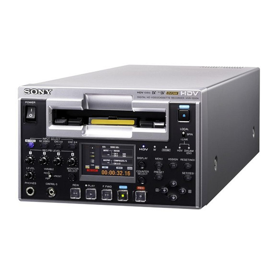
Page 12: Names And Functions Of Parts
Names and Functions of Parts Front panel 6 Cassette compartment POWER EJECT 7 EJECT button 1 POWER switch LOCAL 9PIN i.LINK INPUT SELECT HD VIDEO SD VIDEO CH1 1/2 CH2 3/4 OVER OVER 720 30p 720 HDV DVCAM (DV) REC/PB LEVEL DISPLAY MENU ASSIGN... -
Page 13: Menu Button
k MENU button When the audio level meters are displayed on the LCD monitor, the channel indicators below the level meters are Press this button to display the menu on the LCD monitor highlighted to indicate the channel selection. and an external monitor to which this unit outputs a composite video signal with text information c LEVEL (audio level adjustment) knob superimposed on it. -
Page 14: Hd Video Button
A Video/audio input selection section Each press of this button cycles through the following input video signal selection options. • Composite video signal input to the VIDEO IN connectors (optional HVBK-1505 board required) INPUT SELECT SD VIDEO CH1 1/2 CH2 3/4 HD VIDEO •... - Page 15 When analog audio is selected, the signal input to the • The i.LINK output audio signal levels cannot be AUDIO IN 2/4 connector is recorded either on channel 2 adjusted with the REC/PB LEVEL control knobs. (when in 2- channel mode) or on channels 2 and 4 (when However, when converting a tape recorded in HDV in 4-channel mode).
-
Page 16: Lcd Monitor
C LCD monitor Status display mode 1 System frequency display 2 Recording/playback signal format display qd Audio level meters OVER OVER 720 30p 720 3 HD-SDI output format display INPUT COMPOSITE 4 Input signal display CH-1 AES/EBU CH-2 ANALOG OUTPUT COMPONENT SD 5 Output signal display CH-1 / 2... -
Page 17: Output Signal Display
Indicator in Signal format Note audio area When an option board is required for signal input, the CH-2 3/4 The indicator corresponding to the corresponding indicator does not light unless the option (ANALOG, AES/ signal format selected for audio input to board is installed in the unit. - Page 18 • During recording or when in E-E mode, this indicates the Connectors Output signal setting of the audio recording mode set with the REC (SUPER) CPST Composite video signal MODE menu item (see page 83). 48K: 2-channel mode (48 kHz) •...
-
Page 19: Monitor Area
m Audio level meters b Remote control switch These indicate the audio recording levels (during Select whether operation of this unit is controlled from the recording) or audio playback levels (during playback) of front panel, or from an external device (using i.LINK or channels 1 and 2 or 1 to 4. -
Page 20: Play Button
• To cue up to point A or B: Timecode display Operation to carry out Display the timecode of point Press the </A button. Cueing up Operation to carry out A in the time counter display Cues up to point B Press the ,/B button and F FWD Display the value of (point B Press the </A and ,/B button or REW button at the same time. -
Page 21: Rear Panel
Rear panel 1 -AC IN connector AC IN AUDIO VIDEO IN Y/S-Y/CPST R-Y/S-C 1 Analog video/audio signal input section (see page 22) AUDIO REF.VIDEO VIDEO OUT (SUPER) IN(SD/HD) Y/CPST Pr/R-Y/S-C Pb/B-Y/S-Y CPST 2 Analog video/audio signal output section (see page 23) IN(SD/HD) OUT1 OUT2 SDI... - Page 22 Note When i.LINK input is selected, the playback output signal does not synchronize to the reference video signal input. 1 Analog video/audio signal input section (optional HVBK-1505 board required) The connectors in this section are available when the optional HVBK-1505 board is installed. 1 VIDEO IN connectors 2 AUDIO IN 1/3, 2/4 connectors AUDIO...
- Page 23 2 Analog video/audio signal output section 1 VIDEO OUT connectors, (SUPER) CPST connector 2 AUDIO OUT 1/3, 2/4 connectors AUDIO (SUPER) VIDEO OUT Pb/B-Y/S-Y CPST Y/CPST Pr/R-Y/S-C a VIDEO OUT connectors, (SUPER) CPST (monitor information from this (SUPER) CPST connector. Set this video output) connector (BNC type) menu item to ON to output or OFF to not output.
-
Page 24: Digital Signal Input/Output Section
3 Digital signal input/output section 1 SD/HD SDI IN connector 2 SDI OUT1, OUT2 connectors 4 AUDIO I/O (AES/EBU) IN 1/2, 3/4 connectors 3 HD SDI 5 AUDIO I/O (AES/EBU) OUT 1/2, 3/4 OUT1, OUT2 connectors connectors IN(SD/HD) SDI OUT1 OUT2 SDI OUT1 OUT2... -
Page 25: Chapter 2 Preparations
Preparations Chapter Press the M button or the m button to select the system Before Using this Unit frequency to use. Press the SET (YES) button. The message “NOW SAVING...” appears on the Setting the system frequency monitor screen, and “Saving...” appears in the time counter display, while the new settings are saved in the This unit is shipped with the system frequency still unset. -
Page 26: Menu Settings
• Items regarding interface (format) selection The menu selection level display appears on the LCD • Items regarding the menu bank operations monitor or the external video monitor. In the figure below, SETUP MENU is selected (shown For details of each menu item, see Chapter 7, “Menus” in reverse video). -
Page 27: Using The Assign Button
On-screen indication Meaning S E T U P M E N U Enhanced M E N U G R A D E : B A S I C An asterisk in a complete Factory default setting * B A S I C Time counter display E N H A N C E D list of settings... -
Page 28: Connecting An External Monitor
You can connect a video monitor to this unit’s video output connectors or to the MONITOR AUDIO connector. The Connect an HD video monitor using method 1 or 2 in following figure shows an example using a Sony LCD the following figure. monitor. -
Page 29: Superimposed Text Information
Indication Description Superimposed Text Count value of the time counter Information Timecode data from timecode reader (factory default setting) User bit data from timecode reader The composite video signals output from the (SUPER) TCR. Timecode data from VITC reader CPST connector can contain superimposed text UBR. -
Page 30: Displaying Supplementary Status Information
Display Operation mode Displaying REC LOCK Recording mode (servo locked) Supplementary Status REC-PAUSE Temporary stop of recording EDIT Edit mode (servo unlocked) Information EDIT LOCK Edit mode (servo locked) JOG STILL Still picture in jog mode JOG FWD Jog mode in forward direction When you set the DISPLAY CONTROL >SUB STATUS JOG REV Jog mode in reverse direction... - Page 31 • When the SUB STATUS menu item is set to TC • When the SUB STATUS menu item is set to AUDIO MODE MIXING On-screen indication Meaning On-screen Meaning indication INT PRST FREE [IP F] The internal timecode generator is operating in FREE RUN mode.
-
Page 32: Time Data Handled By This Unit
• During variable-speed playback, the timecode output Time Data Handled by follows the setting of the MUTING IN SRCH menu item (see page 80). This Unit Using time data allows you to easily check time information, ensure high precision editing, and synchronize multiple devices. -
Page 33: Displaying The Time Data And Operating Mode
The set items are displayed on the monitor screen. Displaying the Time Data You can set the display content of the superimposed and Operating Mode text information, the type and positioning of the characters in the DISPLAY CONTROL menu item (see page 77). - Page 34 Time Time data type Data displayed data type indication on indicator superimposed display During During recording playback Time counter count value (can be reset) Timecode (when recording, the timecode generated by the internal timecode generator is displayed; when playing back, the timecode read from the tape is displayed.)
-
Page 35: Recording Formats And Input/Output Signals
Recording Formats and Input/Output Signals Differences among HDV 1080i, DVCAM, and DV formats The following table shows differences among the HDV 1080i, DVCAM, and DV formats. Item HDV 1080i DVCAM Track width 10 µm 15 µm 10 µm Audio sampling 16 bits: 48 kHz (2 channels 12 bits: 32 kHz (4 channels) 12 bits: 32 kHz (4 channels) - Page 36 Analog signal outputs YES: Output, NO: Not output, —: Not applicable Output Analog video outputs Analog audio outputs Composite 6), 7) Composite S-video Component video Analog audio 6), 7) video (text video information) Y/CPST Pr/R–Y/ Y/CPST, Y/CPST, (SUPER) AUDIO AUDIO MONITOR S-C, Pb/ Pr/R–Y/...
- Page 37 — — i.LINK DV format (DVCAM/DV) — — i.LINK HDV format (1080i) 1) With the HVBK-1505 Analog Input Board (option) installed 12)Only 2-channel audio is supported. 2) It is not possible to input an HD component signal. 3) An SDTI signal is not supported. Notes 4) It is not possible to input a DVCPRO signal.
-
Page 38: Playback Formats And Output Signals
• A tape recorded in HDV format on this unit cannot be thirds of the recording time shown on the cassette. When played on a device that does not support the HDV 1080i recording in DVCAM format on a DVCAM cassette, the format. - Page 39 Digital signal outputs YES: Output, NO: Not output f: Upconverted output is possible when the optional HVBK-1520 Format Converter Board is installed. SDI outputs Digital audio i.LINK outputs Output outputs HD-SDI Digital audio (AES/ SD-SDI EBU) (DVCAM/ (1080i) HD SDI HD SDI AUDIO AUDIO...
-
Page 40: Usable Cassettes
1) The Digital Master series is recommended for professional-use HDV tapes. Digital Master is a trademark of Sony Corporation. Checking the tape for slack Using a paper clip or a similar object, turn the reel gently in the direction shown by the arrow. If the reel does not... -
Page 41: Inserting And Ejecting Cassettes
move, there is no slack. Insert the cassette into the cassette compartment, and after about 10 seconds take it out. Mini size (S) Outer guides (Insert the cassette into the middle of the cassette compartment.) Standard size (L) Paper clip, etc. Reel Tape window facing upward Preventing accidental erasure... -
Page 42: Chapter 3 Recording And Playback
Recording and Playback Chapter • There is momentary breakup in i.LINK (HDV) output at Recording the start of HDV recording. For details of the relation between input signals and recording format, see “Input signals and recording This section describes the necessary settings and formats”... - Page 43 Video input INPUT SELECT Indication in the Selected time data Time data type indicator signal (input button (video/ video area of the connector) audio input input signal Count value of the time selection display, and counter section) indicator that Timecode TC (VITC) lights User bit data...
-
Page 44: Carrying Out Recording
This setting can be changed to –18, –16 or –12 dB Audio mode Audio mode display using the LEVEL SELECT menu item (see page 84). 4-channel mode 32 K For recording in DV (SP) format, the reference level is fixed at –12 dB. Cautions •... - Page 45 stationary while the head drum rotates, and the STOP Indicator It means: button lights. NO EDIT indicator • A tape recorded in DVCPRO format is inserted. If REC INHI appears in the LCD monitor screen Replace the tape with one (in status display mode) recorded in DVCAM format.
-
Page 46: Playback
Reference level for recording in DV (SP) format Playback On many consumer DV devices, recording is carried out at a reference level of –12 dB. Therefore, the reference level for recording in DV (SP) format is fixed at –12 dB on this unit. -
Page 47: Playback Operations
• For outputs from the PHONES jack and MONITOR Playback operations AUDIO connector Use the LEVEL control knob on the front panel (outputs from the PHONES jack on the front panel and the Remote control switch MONITOR AUDIO connector on the rear panel are adjusted). -
Page 48: Operation From An External Device
Playback Image Video output i.LINK Note speed quality output A tape recorded in HDV format cannot be played back in Forward Normal reverse frame-by-frame or reverse slow mode. frame-by- frame To set the maximum speed for fast forward and STILL Normal rewind when the F FWD or REW button is pressed ×–1... -
Page 49: Setting Points A And B For Repeat Playback
The repeat indicator lights. timecode value of the current tape position is set as point A or B, and a message “A set” or “B set” is displayed for Press the SET (YES) button to save the new setting 0.5 second in the time counter display. and close the menu. - Page 50 With SETUP MENU selected, press the ,/B S E T U P M E N U >>> Tape top button. O P E R A T I O N A L F U N C T I O N R E P E A T F U N C T I O N Time counter display R E P E A T T O P : T .
-
Page 51: Cuing Up To Any Desired Position Set As Point A Or B
Press the </A or ,/B button to select the digit in Cueing up to point A: Hold down the </A button, and the timecode value display that you want to change. press the F FWD button or REW button. Cueing up to point B: Hold down the ,/B button, and Each press of the button causes the digit to the left or press the F FWD button or REW button. -
Page 52: Chapter 4 Using Time Data
Using Time Data Chapter timecode (or user bit data) from any initial value set on Recording Timecode and this unit (TC insert function). • When i.LINK input is selected, signals played back on User Bit Data this unit do not synchronize to the input reference video signal. -
Page 53: Recording Timecode To Continue From Previously Recorded Timecode
Press the COUNTER SELECT button to light the time • For HDV 1080i format, the user bit data can only be data type indicator TC or UB. recorded every 3 frames. TC: To set the initial timecode value Use the </A and ,/B buttons to move the UB: To set user bit data flashing digit to the value to be changed. -
Page 54: Synchronizing The Internal Timecode Generator To An External Timecode - External Synchronization
External Video signal Menu settings on Note timecode and this unit input source When the recording format of the tape is HDV, this setting input source is not available. MODE SELECT VITC in analog Analog video VITC video signal input connector REGEN Synchronizing the internal timecode VITC in DV... -
Page 55: Outputting Timecode
To record VITC (DVCAM recording only) Outputting Timecode To record VITC on a tape, set the TIME CODE >VITC menu item to ON, and carry out recording (even if VITC is set to OFF, any VITC signal included in input video is recorded unchanged). -
Page 56: Timecode Output During Recording And In E-E Mode
Embedded timecode in SDI output With an appropriate menu setting, this unit can also output SDI embedded timecode as LTC in the SDI output, compliant with the RP188 standard. Embedded timecode in HD-SDI output The HD-SDI output from this unit includes HDV timecode as LTC and VITC compliant with the ARIB STD-B4.2.0 standard and RP188 standard. -
Page 57: Chapter 5 Connections And Settings For Editing
For advice between DV/DVCAM format and HDV format, according about choosing devices, please contact your Sony dealer or to the input selection and the format recorded on the tape. a Sony sales representative. -
Page 58: Using In A Cut Editing System
not operate correctly. Before use, be sure to check that high-voltage current (8 to 40 V) is output from the HDV/ this unit is recommended as supported by the software. DV connector of the device to this unit, which may cause •... - Page 59 the same. If the audio modes are different, an alarm is displayed to tell that editing is impossible. 1 75 Ω coaxial cable (not supplied) DSR-2000A/2000AP Settings on this unit (recorder) settings 2 Pin plug cable (not supplied) INPUT SELECT menu item: Remote control switch: i.LINK i.LINK...
-
Page 60: Connections For A Linear Editing System
Connections for a Linear Editing System - For linear editing using an i.LINK input, if controlled Notes through the RS-422A interface, the edit points are • When using this unit as a recorder for editing in offset. Use i.LINK also for control interface. DVCAM format •... - Page 61 1 75 Ω coaxial cable (not supplied) SD monitor Composite video input 2 9-pin remote cable (not supplied) Audio input 3 XLR cable (not supplied) VIDEO OUT (SUPER) B-Y/CPST MONITOR DSR-1500A/ 4 Pin plug cable (not supplied) 1500AP Reference video signal (player) REF.
- Page 62 DSR-1500A/1500AP (player) settings RM-280 Editing Controller settings Settings on this unit REMOTE I/F menu item: 9PIN Setup menu 01 PREROLL: 5s Video input: COMPOSITE Setup menu 05 SYNC SEL: ON Audio input CH1 1/2: ANALOG, CH2 3/4: ANALOG Setup menu 06 SYNC VTR: TC MODE menu item: INT PRESET RECORDER Setup menu 09 EDIT DLY: AUTO...
-
Page 63: When Using This Unit As An Hdv Tape Player
• DSR-1500A • DSR-1500AP When using this unit as an HDV tape player Using a BVE-700/700A which uses an HDW-M2000/M2000P as the recorder, this unit as the player, and a BVE-700/700A Editing Control The following figure shows a connection example for an Unit. - Page 64 HDW-M2000/M2000P (recorder) BVE-700/700A Editing Control Unit Setting on this unit settings settings REMOTE 1(9P) button: lit PREROLL & PLAY menu item selected Remote control switch: 9PIN REF.VIDEO INPUT connector 75 Ω termination switch: ON Audio selection function switching button INPUT button: HDSDI Function menu HOME >F1 (VID.
-
Page 65: When Using The Editing Functions Of The Recorder
When using the editing functions of HDW-M2000/M2000P Settings on this unit (recorder) settings the recorder REMOTE 1(9P) button: lit Remote control switch: 9PIN The following figure shows an HD cut editing system REF.VIDEO INPUT connector 75 Ω termination switch: ON comprising this unit as the player, and an HDW-M2000/ M2000P unit as the recorder. -
Page 66: Chapter 6 Using The I.link Connector For Dubbing And Tc Insert
Using the i.LINK Connector for Dubbing and TC Insert Chapter Digital Dubbing HVR-Z1 (player) In addition to straightforward tape dubbing, you can also use this unit to dub signals in HDV 1080i or DVCAM/DV format automatically from the beginning of the tape to the end through the i.LINK interface. -
Page 67: Digitally Dubbing Signals In Hdv/Dvcam/Dv Format
Digitally dubbing signals in HDV/ MENU ASSIGN RESET(NO) DVCAM/DV format 1,7,10 PRESET SET(YES) Notes • The maximum recording time differs depending on the 2,4,5 recording format even if using a tape with the same maximum recording/playback time (see page 40). To carry out dubbing, set the recording format to the format 3,5,6 output from the player, or use a tape with longer... - Page 68 The tape is automatically wound back to the Dispaly of setting Description beginning, and dubbing starts. A/V [> A/V] Dub the audio and video. i . L I N K D U B B I N G : H D V Executing ( A / V / T C / C M ) Time counter display...
- Page 69 If the following message appears in step 8 for an i . L I N K D U B B I N G : H D V Executing A/V/TC/CM dubbing operation ( A / V / T C / C M ) Time counter display E X E C U T I N G .
-
Page 70: Rerecording The Timecode - Tc Insert Function (Dvcam Format Only)
S Y S T E M M E N U Setup menu Rerecording the S E T U P M E N U A U T O F U N C T I O N Time counter display H O U R S M E T E R Timecode –... -
Page 71: Dvcam Format
T C I N S E R T : D V C A M Note Not DVCAM! N O T C I N S E R T F U N C T I O N Time counter display If the recording format is not DVCAM, a different A V A I L A B L E , D V R E C O R D I N G F O R M A T S E L E C T E D . -
Page 72: Chapter 7 Menus
Menus Chapter Menu Organization The menu system consists of three subsystems: SETUP MENU, AUTO FUNCTION (auto mode execution) menu and HOURS METER (digital hours meter display) menu. Pressing the MENU button displays the menu selection screen, which allows you to select a menu from among these three menus. - Page 73 In the figure below, items shown in bold type are BASIC (basic items), and other items are ENHANCED (enhanced items). Menu organization Menu selection level Level 1 Level 2 Level 3 SETUP MENU OPERATIONAL FUNCTION REPEAT FUNCTION REPEAT MODE REPEAT TOP REPEAT END A PRESET B PRESET...
- Page 74 Menu selection level Level 1 Level 2 Level 3 (Continued) VIDEO CONTROL STILL MODE INT VIDEO SG STD/NON-STD OUT REF SEL SETUP REMOVE SETUP ADD CC(F1) BLANK CC(F2) BLANK WIDE MODE C PHASE MODE ESR MODE ADJ RANGE SD PROCESS CONTROL VIDEO GAIN CHROMA GAIN CHROMA PHASE...
-
Page 75: Menu Contents
Menu Contents Setup menu Examples: The purpose and settings of the setup menu items are described below. Indication on monitor Indication in time counter Indications of menu items and settings screen display In the table below entitled “Menu contents”, the indication OPERATIONAL FUNCTION [Operational] of each menu item or setting on the monitor screen is CASSETTE OUT... - Page 76 OPERATIONAL FUNCTION [Operational]: Operation Description of settings settings AUTO EE SELECT [> Auto CASSETTE OUT [>> Cass. *EE [>>> EE]: Outputs video and audio signals received from EE]: Determine whether out]: Specify how the other equipment. the unit enters E-E mode unit behaves when the PB [>>>...
- Page 77 OPERATIONAL FUNCTION [Operational]: Operation Description of settings settings MAX SRCH SPEED [> Max SHUTTLE DV [>> SHUTL ×60 [>>> ×60]: Maximum 60 times normal speed SRCH]: Specify the DV]: Specity the *×32 [>>> ×32]: Maximum 32 times normal speed maximum tape speed in maximum speed in ×16 [>>>...
- Page 78 DISPLAY CONTROL [Display]: Settings related to monitor Description of settings display and indicators CHARA. POSITION [> Chara pos]: Set the position of text • To adjust the text display position in the vertical direction, use superimposed on the video signal output from the the M and m buttons.
- Page 79 DISPLAY CONTROL [Display]: Settings related to monitor Description of settings display and indicators OVER DISP HOLD [> Hold OVER]: Determine whether or not *OFF [>> OFF]: Do not hold the OVER indicator. to hold the OVER indicator on the audio level meters once ON (HOLD) [>>...
- Page 80 TIME CODE [Time code]: Settings related to the timecode Description of settings generator TC SELECT [> TC select]: Determine which to display in the VITC [>> VITC]: Display VITC. time counter display, TC or VITC. *TC [>> TC]: Display TC. Note TC is always displayed regardless of the setting of this menu item during the HDV mode.
- Page 81 TAPE PROTECTION [Tape protct]: Settings related to tape Description of settings and video head protection FROM STOP [> From STOP]: STOP TIMER [>> STP 0.5 SEC [>>> 0.5 sec] to 5 MIN [>>> 5 min]: Select time from Set the time to switch from timer]: Set the time to 12 settings ranging from 0.5 second to 5 minutes.
- Page 82 VIDEO CONTROL [Video]: Settings related to video Description of settings control SETUP ADD [> Setup add]: Determine whether or not to add *OFF [>> OFF]: Do not add black setup. black setup to analog video output signals. ON (ADD) [>> ON]: Add black setup. Note Displayed only when the system frequency is set to 60i.
- Page 83 VIDEO CONTROL [Video]: Settings related to video Description of settings control HD PROCESS CONTROL ADJ RANGE [>> Adj range]: *–3 to +3(db) [>>> –3/+3]: –3 dB to +3 dB [> HD Process] Select the adjustment WIDE [>>> wide]: –∞ to +3 dB range for video gain and chrominance gain.
- Page 84 AUDIO CONTROL [Audio]: Settings related to audio Description of settings control LEVEL SELECT [> Level Sel] REF LEVEL [>> REF Level]: *–20 dB [>>> –20dB]: Set to –20 dB. Select the audio –18 dB [>>> –18dB]: Set to –18 dB. reference level –16 dB [>>>...
- Page 85 AUDIO CONTROL [Audio]: Settings related to audio Description of settings control DV PB ATT [> DV PB ATT]: When playing back a tape OFF [>> OFF]: Do not attenuate. recorded in consumer DV format, select whether to *ON [>> ON]: Attenuate. attenuate the audio output level.
-
Page 86: Auto Mode Execution (Auto Function) Menu
INTERFACE SELECT [Interface]: Settings related to Description of settings external interfaces SDI H-ANC [> SDI H-ANC]: RP188LTC [>> RP188LTC]: OFF [>>> OFF]: Do not embed an LTC signal. Select whether to add RP188 timecode *ON [>>> ON]: Output an embedded LTC signal. RP188 LTC and aspect ASPECT [>>... - Page 87 Menu contents i.LINK DUBBING: HDV [i.LINK DUB]: Selection of data for Description of settings i.LINK dubbing For dubbing through the i.LINK interface in HDV format, A/V [> A/V]: Dub the audio and video. select data to be dubbed. A/V/TC [> A/V/TC]: Dub the audio, video, and timecode. A/V/TC/CM [>...
-
Page 88: Changing Menu Settings
Changing Menu Settings MENU ASSIGN RESET(NO) SET(YES) PRESET This section explains how to change menu settings. 3,5,7 Buttons used to change menu 2,4-6 settings Use the following buttons in the front panel to change menu settings. Press the MENU button. Menu control Functions buttons... - Page 89 S E T U P M E N U S E T U P M E N U Display >>x2 O P E R A T I O N A L F U N C T I O N D I S P L A Y C O N T R O L D I S P L A Y C O N T R O L C H A R A .
-
Page 90: Displaying Enhanced Menu Items
The menu selection level display appears on the On-screen indication Meaning monitor. Character string at the right Current setting of the menu of a menu item item With SETUP MENU selected, press the ,/B When shown with a colon button. (:): the current setting is the same as the factory This displays all basic and enhanced items on menu... -
Page 91: Assigning A Function To The Assign Button
Press the SET (YES) button. Assigning a Function to The setting returns to its factory default and is saved in memory. the ASSIGN Button To return all settings to their factory default settings You can assign a desired menu item (a function, in other words) on level 1 or level 2 to the ASSIGN button. - Page 92 • When the menu item you want to assign is on S E T U P M E N U Operational O P E R A T I O N A L F U N C T I O N level 2: go to step 7 D I S P L A Y C O N T R O L Time counter display...
-
Page 93: Chapter 8 Maintenance And Troubleshooting
Maintenance and Troubleshooting Chapter Do not obstruct ventilation openings Important Notes on To prevent the unit from overheating, do not obstruct ventilation openings, by for example wrapping the unit in Operation a cloth while it is in operation. On cleaning On safety If the casing or panel is dirty, wipe it gently with a soft dry •... -
Page 94: Condensation
Use them as guidelines for scheduling maintenance. from the air may condense on the head drum. This is called In general, consult your Sony dealer about necessary condensation, and if a tape is run in this state, the tape may periodic maintenance checks. - Page 95 Press the MENU button. display. To reset the trip values Digital hours meter indications on the monitor About this operation, consult your Sony dealer. screen All four counts (T1, T2, T3, and CT) are indicated on the monitor screen. Resettable trip counts...
-
Page 96: Head Cleaning
Head Cleaning Always use the PDVM12CL (mini size) or PDV12CL (standard size) Cleaning Cassette to clean the video and audio heads. You can run the cleaning cassette for 10 seconds per cleaning operation. Follow the instructions for the cleaning cassette, as inappropriate use of the cleaning cassette can damage the heads. -
Page 97: Troubleshooting
Troubleshooting If an alarm message appears on the monitor screen, or if the unit appears to be malfunctioning, please check the following before contacting your Sony dealer. Tape problems Symptom Cause Remedy Recording is not possible. The cassette’s REC/SAVE Set the REC/SAVE switch to REC, or use another cassette. -
Page 98: Alarm Messages
Monitor problems Symptom Cause Remedy (see page 77) Data is not superimposed on The CHARA. DISPLAY menu Set the CHARA. DISPLAY menu item to ON. the monitor screen. item is set to OFF. The monitor is not connected Connect the monitor to the (SUPER) CPST connector. to the (SUPER) CPST (You must make this connection to display any type of text on connector of this unit. - Page 99 Alarm message on monitor Direction Alarm message in time counter display screen (Cause) THE SELECTED AUDIO MATCH AUDIO RECORDING MODE A mode err! RECORDING MODE IS SELECTION WITH THE ONE ON THE DIFFERENT FROM THE AUDIO TAPE. FORMAT OF THE TAPE. NO CASSETTE ADAPT CAN BE EVEN IF THE CASSETTE IS OF MINI Adaptor!
- Page 100 Alarm message on monitor Direction Alarm message in time counter display screen (Cause) INPUT SIGNAL IS NOT A – Unknown sig DVCAM/DV SIGNAL. CHANGE THE HD/SD SETTING. CHANGE SEL CHANGE THE HDV/DV SETTING. THIS TAPE CANNOT BE 50i Tape PLAYED BACK UNLESS THE CURRENT SETTING OF 60i Tape SYSTEM FREQUENCY IS...
-
Page 101: Error Messages
Appears when an error is detected in the CPU peripheral system or IC control communications When an error message appears, follow the instructions on the monitor screen for resolving the problem. When an error message persists, contact your Sony dealer or a Sony service representative. Troubleshooting... -
Page 102: Appendix
IEEE 1394 proposed by Sony, is a trademark supported by many companies worldwide. IEEE 1394 is an international standard defined by IEEE, the Institute of Electrical and Electronics Engineers, Inc. -
Page 103: Specifications
Specifications General Signal system 1080/60i format, NTSC color, EIA standard 1080/50i format, PAL color , CCIR standard Audio recording format (HDV) MPEG-1 Audio Layer 2 (2-channel) 16 bits, 48 kHz (stereo), bitrate 384 kbps Audio recording format (DVCAM/DV) 12 bits, sampling frequency 32 kHz (4- channel) 16 bits, sampling frequency 48 kHz (2- channel) -
Page 104: Processor Adjustment Range
When controlling from DSRM-10 Remote Control Input connectors Unit: Digital signal inputs DV/DVCAM/DVCPRO: SD/HD SDI IN BNC type (1), Serial digital (270 Mbps), Jog mode: 0 (still) to 2 times normal SMPTE 259M/ITU-R BT.656 speed in both directions HD-SDI format, SMPTE 292M Shuttle mode: 0 (still) to 16 times compliant normal speed in both directions... - Page 105 59.94), EBU timecode (625/50), 2.2Vp-p • Always verify that the unit is operating properly ±3 dB (when 600 Ω terminated), before use. SONY WILL NOT BE LIABLE FOR unbalanced DAMAGES OF ANY KIND INCLUDING, BUT NOT LIMITED TO, COMPENSATION OR...
-
Page 106: Glossary
Condensation serial interface defined by SMPTE Glossary 292M. Condensation of moisture on the tape transport mechanisms of VCRs HD tri-level sync including the head drum. If moisture A/B roll editing condenses on the head drum, the tape An HDTV analog reference signal adheres to the drum and causes that applies to 59.94/50Hz systems. - Page 107 video and digital television Television Engineers (SMPTE) for to the video heads and the tape, but transmission, it maintains high image transmitting control codes and the VCR is not ready for immediate quality while achieving high timecode in the ancillary data space recording or playback.
- Page 108 base correction reduces deterioration of picture quality when transmitting or copying playback signals. Threading See “Loading.” Timecode A digitally encoded signal which is recorded with video data to identify each frame of the video by hour, minute, second and frame number. SMPTE timecode is applied to NTSC system, and EBU timecode to PAL and SECAM systems.
-
Page 109: Index
Display Index full screen display mode 13 Menu 72 small screen display mode 13 auto mode execution menu 86 status display mode 13 BASIC menu 25, 88 DISPLAY button 13 changing settings 26, 88 Dubbing 66 contents 75 AC IN connector 21 DVCAM format 8 ENHANCED menu 25, 90 Alarm messages 98... - Page 110 Remote VIDEO IN connectors 22 control 10, 48 VIDEO OUT connectors 23 control connectors 105 Video/audio input selection section 14 control switch 19 VITC REMOTE connector 21 indicator 18 Remote control switch/indicator section 19 REPEAT indicator 18 Repeat playback 48 RESET (NO) button 13 REW button 20 SD VIDEO button 14...