Fujitsu PRIMERGY TX300 S4 User Manual
Hide thumbs
Also See for PRIMERGY TX300 S4:
- Options manual (137 pages) ,
- Operating manual (121 pages) ,
- System configuration and order-information manual (17 pages)
Table of Contents
Advertisement
Quick Links
Areas Covered
Before Reading This Manual
This section explains the notes for your safety and conventions used in this manual.
Chapter 1
Overview
This chapter explains component names and basic operations of this server, as well as an
overview of the software provided with this server. In addition, the workflow, from placing the
server to starting the operation, is also described.
Chapter 2
Checking before OS Installation
This chapter explains the preparation and cautions for the server before OS installation. Observe
this chapter before starting installation.
Chapter 3
OS Installation
This chapter explains how to install the OS in the server using ServerStart.
Chapter 4
Operations after OS Installation
This chapter explains the operations to be performed after OS installation. Be sure to perform
these operations before operating the server.
Chapter 5
High Reliability Tools
For stable PRIMERGY server operations, we recommend that high reliability tools be installed.
This chapter explains the installation and necessary settings of high reliability tools.
Chapter 6
Installing Internal Options
This chapter explains how to install and remove the various hardware options.
Chapter 7
Configuring Hardware and Utilities
This chapter explains how to make the environment settings necessary to operate the server and
how to use each utility.
Chapter 8
Operation and Maintenance
This chapter explains the operations that become necessary after starting to use this server in
addition to daily care and maintenance.
Appendix
This appendix explains the specifications for the server and for its internal options.
PRIMERGY TX300 S4 User's Guide
1
Advertisement
Table of Contents
Troubleshooting

Related Manuals for Fujitsu PRIMERGY TX300 S4


Summary of Contents for Fujitsu PRIMERGY TX300 S4
- Page 1 PRIMERGY TX300 S4 User's Guide Areas Covered Before Reading This Manual This section explains the notes for your safety and conventions used in this manual. Chapter 1 Overview This chapter explains component names and basic operations of this server, as well as an overview of the software provided with this server.
-
Page 2: For Your Safety
Note that data protection is not guaranteed when repairs are performed. It is the customer's responsibility to maintain backup copies in advance. In case of data loss, Fujitsu assumes no liability for data maintenance or restoration and damages that occur as a result of the data loss for any reason, except for items covered under warranty. - Page 3 PRIMERGY TX300 S4 User's Guide Remarks Warning descriptions Various symbols are used throughout this manual. These are used to emphasize important points for your safety and that of others. The following are the symbols and their meanings. Fully understand these symbols when reading this manual.
- Page 4 Entering commands (Keys) Command entries are displayed in the following way. • At each blank in a command line (as pointed out above), press the [Space] key once. • When using Windows or DOS OS, commands are not case sensitive. •...
- Page 5 PRIMERGY TX300 S4 User's Guide Abbreviations The following expressions and abbreviations are used throughout this manual. table: Abbreviations of product names Product name Expressions and abbreviations PRIMERGY TX300 S4 (SAS model) SAS model TX300 S4 or the server PRIMERGY TX300 S4 (SATA model) SATA model ®...
-
Page 6: Reference Information
PRIMERGY TX300 S4 model descriptions PRIMERGY TX300 S4 has SAS model and SATA model. Herein, unless otherwise noted, these descriptions apply to both models. For descriptions unique to a given model, a model name is cited. Before reading this manual, check the "model label" attached to the following location on each server. -
Page 7: Table Of Contents
PRIMERGY TX300 S4 User's Guide Contents Chapter 1 Overview 1.1 TX300 S4 ..........14 1.2 Supplied Software . - Page 8 3.2.4 Application Wizard ......... . . 72 3.2.5 Starting OS Installation .
- Page 9 PRIMERGY TX300 S4 User's Guide 5.2.2 Setting Required after Installation ......129 5.3 Maintenance Support Tool [HRM/Server] .
- Page 10 Chapter 7 Configuring Hardware and Utilities 7.1 Switch Block Settings ....... . 192 7.2 BIOS Setup Utility .
-
Page 11: Remote Management Controller
PRIMERGY TX300 S4 User's Guide 8.6.2 For Windows Server 2003 ........247 8.7 Reinstalling the OS . -
Page 13: Chapter 1 Overview
Chapter 1 Overview This chapter explains component names and basic operations of this server, as well as an overview of the software provided with this server. In addition, the workflow, from placing the server to starting the operation, is also described. -
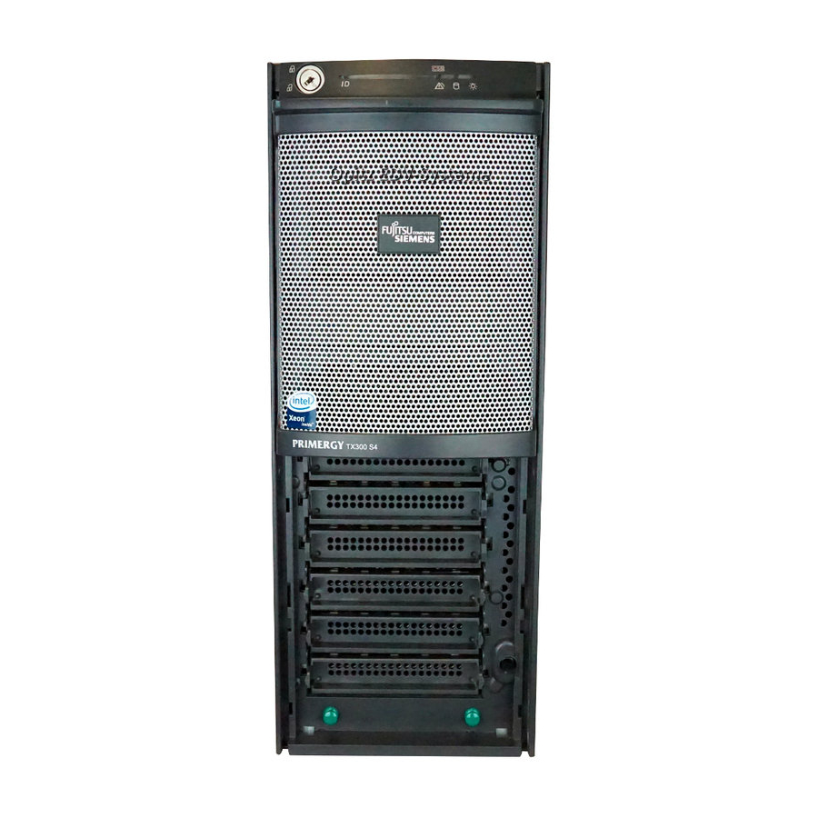
Page 14: Tx300 S4
Chapter 1 Overview 1.1 TX300 S4 This is a tower type server with high-performance, high-reliability, and high- scalability, having the following features. High reliability Advanced memory protection function This server supports the Single Device Data Correction (SDDC) function included in PC2-5300F (DDR 2-667)-compliant memory module (Fully Buffered DIMM). -
Page 15: High Reliability Tools
PRIMERGY TX300 S4 User's Guide High reliability tools High reliability tools, such as ServerView which is a tool for monitoring the server status, offer further stable system operation. Refer to "1.2.2 High Reliability Tools" ( pg.19) for details. High-speed processing Intel ®... -
Page 16: Supplied Software
Chapter 1 Overview 1.2 Supplied Software The following software is supplied together with the server. ServerStart supports setting up the system and high reliability tools to prevent troubles while server system is running. 1.2.1 Setup Support Tool - ServerStart ServerStart is an initial setup support tool for PRIMERGY. It offers simple procedures for setup and proper installation for recommended drivers. -
Page 17: Main Window
PRIMERGY TX300 S4 User's Guide Some operations such as a license window and media replacements are required to be performed manually. High reliability tools are software with comprehensive strength for stable system operation of the server management. Merit with ServerStart setup Network configuration (only for Windows Server 2003) ServerStart can configure a network on server installation. -
Page 18: Tool Bar
Chapter 1 Overview Tool bar For the Expert mode Goes to the Returns to the Changes the size Ends ServerStart. next page. previous page. of icons. Returns to Goes to one tier Resets the status the main screen. upper. function. While the wizard is running, do not click the icon to move to the previous or next window or to upper tree level. -
Page 19: High Reliability Tools
PRIMERGY TX300 S4 User's Guide 1.2.2 High Reliability Tools High reliability tools provide comprehensive supports for stable system operations of the server. The following tools have individual management function through normal operations to restoration from errors: • Server monitoring tools •... -
Page 20: Installing High Reliability Tools
Chapter 1 Overview LAN driver advanced setup tools These tools set details on the LAN, including the teaming (load balance) function and VLAN configuration. Broadcom Advanced Control Suite (BACS) BACS is a tool for setting details on the onboard LAN, such as when configuring VLAN with an onboard LAN. - Page 21 PRIMERGY TX300 S4 User's Guide When using ServerStart to install the OS, RAID Management Tool and ServerView Agent are installed together. These cannot be selected individually. Also, the selection cannot be cleared. To use all functions of ServerView, "Java2 Runtime Environment Standard Edition" and "Web server"...
-
Page 22: Component Names And Functions
Chapter 1 Overview 1.3 Component Names and Functions This section explains the component names and functions of the server and baseboard. 1.3.1 Server (front view) a b c d e f g h Drive cover Pull down this drive cover to the bottom. -
Page 23: Reset Switch
PRIMERGY TX300 S4 User's Guide d Reset switch Pressing this switch resets and restarts the system. Do not restart the system when the hard disk access LED is blinking. Data in the hard disk may be damaged. e Maintenance switch This switch is used only by maintenance personnel. - Page 24 Chapter 1 Overview q Floppy disk access LED This LED blinks when data is being written to or read from a floppy disk. Inside the hard disk cover Hard disk cover Remove the hard disk cover. a 3.5-inch storage bay Those storage bays contain internal hard disk units.
-
Page 25: Server (Rear View)
PRIMERGY TX300 S4 User's Guide 1.3.2 Server (rear view) [For Power Supply Conversion kit] a Power supply unit When using a Power Supply Conversion kit, the redundant function for power supply units takes effect since two power supply units are installed. The power supply unit 1 is on the right side and the power supply unit 2 is on the left side. -
Page 26: Keyboard Connector
Chapter 1 Overview f System status LED This LED is lit or blinking yellow when an error is detected in the server components. If this LED is lit or blinking, contact an office listed in the "Contact Information" of "Start Guide". g Keyboard connector ( Connect a keyboard. - Page 27 PRIMERGY TX300 S4 User's Guide o LAN cable removal lever To disconnect the LAN cable attached to the LAN port 1, release the lock of the lever by pulling down the lever and pull out the cable. LAN cable If there is difficulty due to the cable type, hold a tab on the top of the LAN cable connector with a flathead driver, and pull out the LAN cable.
-
Page 28: Server (Internal)
Chapter 1 Overview 1.3.3 Server (internal) [Rear] [Front] a Power supply unit When using a Power Supply Conversion kit, the redundant function for power supply units takes effect since two power supply units are installed. b 5-inch storage bay Install a 5-inch internal optional device. c Internal hard disk bay Install an internal hard disk unit. -
Page 29: Baseboard
PRIMERGY TX300 S4 User's Guide 1.3.4 Baseboard [Rear] [Front] a Parallel port connector Connect a parallel port cable when using a parallel port option. b Memory board slot Install a memory board. A memory board is installed as a standard feature. Up to eight memory modules can be installed on a memory board. -
Page 30: Pci Slot
Chapter 1 Overview j USB connector 1 When installing 5-inch internal options with USB-compliant, connect a USB cable. k PCI slot Install expansion cards. PCI slots (1 to 7) are numbered from bottom to top in the figure of baseboard. Slot 1 is installed with a SAS controller card or a SAS array controller card as a standard feature. -
Page 31: Standard Operations
PRIMERGY TX300 S4 User's Guide 1.4 Standard Operations This section explains standard operations such as turning the server on/off and handling the disk drive. 1.4.1 Sliding the Drive Cover When using a floppy disk drive, a CD/DVD drive and a 5-inch storage bay option, slide the drive cover to the bottom of the server. -
Page 32: Opening The Rack Door
Chapter 1 Overview The drive cover key is unique to each device. Do not lose the key. If the key is lost, the lock must be broken and replaced for value. Manage the drive cover key very carefully. Contact an office listed in the "Contact Information"... - Page 33 PRIMERGY TX300 S4 User's Guide Turn the handle in the direction of the arrow, and pull it. Turn and then pull Opening the rear door Turn the rack key, and pull the rack handle up.
-
Page 34: Turning On The Server
When operating the device outside of this operating environment, the server may operate improperly, damage data etc. Furthermore, Fujitsu cannot be held responsible for any related damage, malfunction, or loss of data, etc. • The fans rotate at high speed immediately after the server is turned on, but this is not defective. -
Page 35: Turning Off The Server
PRIMERGY TX300 S4 User's Guide Slide the drive cover. "1.4.1 Sliding the Drive Cover" (pg.31) Make sure that the floppy disk drive and CD/DVD drive are empty. Turn on the display and peripheral devices. Press the power switch on the front of the server. - Page 36 Chapter 1 Overview Shut down the OS. In the following cases, the server is turned off after the OS is shut down (Step 4 is not necessary). • Windows OS • ServerView is installed In other cases, make sure that the access LEDs of floppy disk and hard disk are off when the OS is shut down.
-
Page 37: Inserting And Ejecting A Floppy Disk
PRIMERGY TX300 S4 User's Guide 1.4.5 Inserting and Ejecting a Floppy Disk Cautions When using floppy disks, note the following points to avoid failures: • Do not expose the disk to any fluids. • Do not open the shutter of the floppy disk and touch the disk surface. -
Page 38: Inserting And Ejecting A Cd/Dvd
Chapter 1 Overview Ejecting a floppy disk Make sure that the floppy disk access LED is off. Do not eject a floppy disk while the floppy disk access LED is lit. Doing so may damage data. Press the floppy disk eject button. The floppy disk comes out. - Page 39 PRIMERGY TX300 S4 User's Guide Cautions for handling media • Hold CD/DVDs by their edges to avoid contact with the disc surface. • Do not contaminate the CD/DVD surface with fingerprints, oil, dust, etc. If dirty, clean with a soft, dry cloth, wiping from the center to the edge.
- Page 40 Chapter 1 Overview Place the CD/DVD (label side up) on the tray. Press the CD/DVD eject button again. The tray is inserted into the server, and CD/DVD is set. When CD/DVD is set, the CD/DVD access LED is lit. To go to next operation, confirm that the LED is off.
-
Page 41: Workflow
PRIMERGY TX300 S4 User's Guide 1.5 Workflow To start the server operation, perform the following procedures. Installing the server Refer to "Safety Precautions" and "Start Guide" to install the server on a suitable location. Preparing the server - Install internal options - Set configurations of hardware Refer to "2.1 Preparation on the Server", "Chapter 6 Installing Internal Options"... - Page 42 Chapter 1 Overview...
-
Page 43: Chapter 2 Checking Before Os Installation
Chapter 2 Checking before OS Installation This chapter explains the preparation and cautions for the server before OS installation. Observe this chapter before starting installation. 2.1 Preparation on the Server ......2.2 Selecting an Installation Method . -
Page 44: Preparation On The Server
Chapter 2 Checking before OS Installation 2.1 Preparation on the Server Before starting OS installation, prepare the server and perform hardware settings. 2.1.1 Installing Options For details on how to install internal options, refer to "Chapter 6 Installing Internal Options" ( pg.133). Installing 5-inch internal device options To install an OS with 5-inch internal device options installed, check the following points. -
Page 45: Lan Cable
PRIMERGY TX300 S4 User's Guide Cautions for installing a memory module The supported maximum capacity varies depending on the OS to be installed. Furthermore, since the server uses part of memory as PCI resources, the maximum available capacity has limitation. The table below describes maximum installable memory capacity and available memory capacity. -
Page 46: Hardware Settings
Chapter 2 Checking before OS Installation 2.1.2 Hardware Settings In the following cases, setting BIOS Setup Utility is required before OS installation. For details on how to set BIOS Setup Utility, refer to "7.2 BIOS Setup Utility" ( pg.193). When changing boot drives To change boot drives, start up BIOS Setup Utility, select the [Boot] menu, and then change boot drives. -
Page 47: Selecting An Installation Method
PRIMERGY TX300 S4 User's Guide 2.2 Selecting an Installation Method When installing an OS with ServerStart, there are multiple installation methods. Prior to OS installation, decide which mode to use for the installation. 2.2.1 Supported OS The following operating systems can be installed by using ServerStart V7.808. -
Page 48: Expert Mode
Chapter 2 Checking before OS Installation Expert mode In this mode, start up Disk Manager and format the partition where your OS is installed prior to installation of the OS. Select the Expert mode only when installing the OS while maintaining the existing partitions. -
Page 49: Precautions On Installation
PRIMERGY TX300 S4 User's Guide 2.3 Precautions on Installation Observe the following notes before starting OS installation. 2.3.1 Installation Partition Size The installation partition sizes are stated as below when using ServerStart to install your OS. • Maximum size: 2TB •... -
Page 50: Cautions For Using Serverstart
Chapter 2 Checking before OS Installation When using a SAS array controller card (MegaRAID SAS) Configure a RAID with internal hard disk units that are connected to a SAS array controller card. The array controller to be employed is "MegaRAID SAS" and available RAID level is "RAID 0 / RAID 1 / RAID 1+0 / RAID 5 / RAID 6". -
Page 51: Setting Up Printers
PRIMERGY TX300 S4 User's Guide Exiting ServerStart After operation in the Expert mode, exiting ServerStart restarts the system. Remove discs from the floppy disk and CD/DVD drives, and click [OK]. When the display on the screen disappears, turn off the system. -
Page 52: Automatic Driver Installation With Serverstart
Chapter 2 Checking before OS Installation 2.3.4 Automatic Driver Installation with ServerStart ServerStart supports automatic driver installation for the following expansion cards. table: Automatic driver installation Onboard controller or card type Product ID Onboard FDD/IDE/SATA – – Onboard SATA – –... -
Page 53: Chapter 3 Os Installation
Chapter 3 OS Installation This chapter explains how to install the OS in the server using ServerStart. 3.1 Quick Installation Mode ......3.2 Expert Mode . -
Page 54: Quick Installation Mode
Chapter 3 OS Installation 3.1 Quick Installation Mode In the Quick Installation mode, the OS is installed after configuring minimum required settings. To install the OS quickly and easily, use the Quick Installation mode. When installing Windows Server 2008, perform "Full installation". When installing Windows Server 2008 (64-bit), and when saving the configuration file to a floppy disk, make sure to change the boot priority in BIOS Setup Utility before starting ServerStart. - Page 55 PRIMERGY TX300 S4 User's Guide Insert the ServerStart floppy disk supplied with the server. Make sure that "on local drive (floppy/USB stick)" and "A:" are selected, and click [Continue]. Set the ServerStart floppy disk in the write-enabled state. When installing the OS without using the ServerStart floppy disk, select [No status backup], and click [Next].
- Page 56 Chapter 3 OS Installation Click [Accept]. The [Welcome to ServerStart] window appears. Select [Quick Installation], and click [Next]. The [Select the Boot Controller and Boot Disk] window appears.
- Page 57 PRIMERGY TX300 S4 User's Guide Set configuration of the RAID and disks, and click [Next]. To install the OS while maintaining the established RAID environment Select "Logical Disk 0", and specify partition size to be created. One partition can be created. Select "Logical Disk 0" even if the RAID is not required to be created.
- Page 58 Chapter 3 OS Installation Select the OS to be installed, and click [Next]. The [Configure your unattended Windows Installation] window appears. Set the items, and click [Next]. The [Summary] window appears. Confirm the settings, and click [Start Installation]. Click [Start now]. Installation starts.
- Page 59 PRIMERGY TX300 S4 User's Guide For Windows Server 2008 (64-bit), a message appears and prompts you to insert the PRIM- ERGY Startup Disc again. Insert the PRIMERGY Startup Disc. After files are copied, a mes- sage prompts you to eject the CD/DVD.
- Page 60 Chapter 3 OS Installation Configure settings for RAID Management Tool (ServerView RAID). For details, refer to the manuals in Array Controller Document & Tool CD. • Setting an array administrator account A Windows user account is required when using ServerView RAID. Create a group named "raid-adm", and create an account with any name for an array administrator within the group "raid-adm".
-
Page 61: Expert Mode
PRIMERGY TX300 S4 User's Guide 3.2 Expert Mode In the Expert mode, start up Disk Manager, format the installation partition, and install the OS. Use this mode only when you want to perform installation while maintaining the existing partitions. Windows Server 2008 cannot be installed in Expert mode. - Page 62 Chapter 3 OS Installation Insert the ServerStart floppy disk supplied with the server. Make sure that "Removable media" and "A:" are selected, and click [Continue]. Set the ServerStart floppy disk in the write-enabled state. When installing the OS without using the ServerStart floppy disk, select [No status backup], and click [Next].
- Page 63 PRIMERGY TX300 S4 User's Guide Click [Accept]. The [Welcome to ServerStart] window appears. Select [Expert Installation], and click [Next]. The [Create a ServerStart Floppy Disk] window appears.
- Page 64 Chapter 3 OS Installation Click [Build a ServerStart Floppy Disk]. Creation of a ServerStart floppy disk starts. When the creation is completed, the "Floppy disk has been created." message appears. Click [OK]. The [Please Select your Keyboard] window appears. Select your keyboard language from the drop-down list, and click [OK]. The subsequent start procedure may take several minutes.
- Page 65 PRIMERGY TX300 S4 User's Guide Click [Install MS (OS) interactively (expertise required)]. The Expert mode starts. Start up the configuration tools to set items. Exiting a tool returns to the display to the Expert mode window. Make sure to open the menu of each wizard and confirm the settings.
-
Page 66: Disk Manager
Chapter 3 OS Installation 3.2.2 Disk Manager Start up Disk Manager, and format the installation partition. Click [Use Disk Manager to partition and format your disk drives]. Disk Manager starts up. Format the OS installation partition. Select the OS installation partition, and click the [Partition] menu –... -
Page 67: Os Installation Wizard
PRIMERGY TX300 S4 User's Guide 3.2.3 OS Installation Wizard Set computer information, user information, and the network protocol. ServerStart can configure multiple network patterns. When configuring a domain controller, refer to "Using ServerStart to Configure the Network". The setup windows vary depending on the OS to be installed. For example, operation on Windows Server 2003 R2 is given below. - Page 68 Chapter 3 OS Installation The [Computer Identification] window appears. Set items, and click [next]. The [Installation Directory and Time Zone] window appears.
- Page 69 PRIMERGY TX300 S4 User's Guide Set items, and click [next]. The [User Name] window appears. Set items, and click [next]. The [Display Settings] window appears. Set items, and click [next]. The [Network Protocol] window appears.
- Page 70 Chapter 3 OS Installation Set items, and click [next]. The [Software Components] window appears. If Windows Server 2003 R2 is selected at the Computer Identification, R2 components are always copied to the hard disk. To install the components, click [Properties], and check the box of the components to be installed.
- Page 71 PRIMERGY TX300 S4 User's Guide Set items, and click [next]. The [Services] window appears. Simple Network Management Protocol is always installed. Click [Properties] to change the set- tings. Set items, and click [leave wizard]. The display returns to the Expert mode window.
-
Page 72: Application Wizard
Chapter 3 OS Installation 3.2.4 Application Wizard Set configurations for installation of supplied applications such as high reliability tools. Open those windows, and confirm the settings carefully. Click [Application Wizard: Select additional software components]. The application wizard appears. From the list in [Installable applications], select application software to be installed, and click [>>]. -
Page 73: Starting Os Installation
PRIMERGY TX300 S4 User's Guide 3.2.5 Starting OS Installation Install the operating system to the server. Notes on the installation When the installation partition is not empty, a confirmation message appears. Unless otherwise considered as problem, click [OK] to continue the installation procedure. - Page 74 Chapter 3 OS Installation When a message prompts you to insert the OS CD/DVD, insert the CD/DVD, and click [OK]. For Windows Server 2003 / Windows Server 2003 x64 1. Insert the OS CD/DVD (Installation disc). The license agreement window appears. 2.
- Page 75 PRIMERGY TX300 S4 User's Guide Configure settings for RAID Management Tool (ServerView RAID). For details, refer to the manuals in Array Controller Document & Tool CD. • Setting an array administrator account A Windows user account is required when using ServerView RAID. Create a group named "raid-adm", and create an account with any name for an array administrator within the group...
- Page 76 Chapter 3 OS Installation...
- Page 77 Chapter 4 Operations after OS Installation This chapter explains the operations to be performed after OS installation. Be sure to perform these operations before operating the server. 4.1 Memory Dump/Paging File Setting ....4.2 Creating Backup Data for System Recovery .
-
Page 78: Chapter 4 Operations After Os Installation
Chapter 4 Operations after OS Installation 4.1 Memory Dump/Paging File Setting Before starting operating this server, configure the setting for obtaining memory dump. Memory dump Debugging information, when memory dump has been set, will be automatically saved in case that a STOP error (fatal system error) occurs in the system. -
Page 79: Memory Dump File Setting
PRIMERGY TX300 S4 User's Guide Kernel memory dump Information of only kernel memory space is recorded. The file is stored in the directory displayed in the [Dump file] box. Capacity required for kernel memory dump is as follows: • Paging file: Depending on installed physical memory amount For memory of 256 to 1,373MB - Installed physical memory ×... - Page 80 Chapter 4 Operations after OS Installation Click the [Advanced] tab, and click [Settings] in [Startup and Recovery]. The [Startup and Recovery] window appears. Complete the settings as follows: 1. In the [Write debugging information] section, select the memory dump file type. •...
-
Page 81: Paging File Setting
PRIMERGY TX300 S4 User's Guide Restart the system. The setting is enabled after the system restarts. Paging file setting Set up the paging file according to the following procedures. Log on to the server with the administrator account. Check free space of the drive where the system has been installed. - Page 82 Chapter 4 Operations after OS Installation Click the [Advanced] tab. For Windows Server 2008 For Windows Server 2003...
- Page 83 PRIMERGY TX300 S4 User's Guide In the [Virtual memory] section, click [Change]. The [Virtual Memory] window appears. For Windows Server 2008 If [Automatically manage paging file size for all drives] is checked, uncheck it. For Windows Server 2003 Select the drive where the paging file is to be created.
- Page 84 Chapter 4 Operations after OS Installation Select [Custom size], and enter a value in [Initial size]. The value depends on the type of the set dump file. Set a value larger than the value shown in [Recommended] in [Total paging file size for all drives].
-
Page 85: Creating Backup Data For System Recovery
PRIMERGY TX300 S4 User's Guide 4.2 Creating Backup Data for System Recovery After OS installation is complete, create backup data for system recovery, which enables the system to be recovered if an error occurred. After OS installation or changing the system configuration, make sure to perform this procedure to create backup data. -
Page 86: Windows Server 2003
Chapter 4 Operations after OS Installation Creating backup data Follow the procedure below to back up the whole server configuration. Click [Start] – [Administrative Tools] – [Windows Server Backup]. From the operation menu, select [Backup Once]. In [Select backup configuration], select [Full server]. In [Specify destination type], select [Remote shared folder]. - Page 87 PRIMERGY TX300 S4 User's Guide Click [Finish]. Backup process starts. If a message prompts you to insert a floppy disk, insert the floppy disk and click [OK]. Automated system recovery disk is created. When the process is completed, a message appears. Eject the floppy disk according to the message, and put a label on it.
-
Page 88: Storing The System Configuration Information
Chapter 4 Operations after OS Installation 4.3 Storing the System Configuration Information Before starting operations and when changing the system configuration information, store the configuration information. By storing this information, the system can be recovered with the stored information in case of a system failure (such as when the baseboard fails). -
Page 89: Information
PRIMERGY TX300 S4 User's Guide 4.3.1 Storing the BIOS Information and the Remote Management Controller Information Store the BIOS information and the Remote Management Controller information according to the following procedures. Before starting the operation, if the boot monitoring function of ServerView is enabled, disable it (it is disabled by default). -
Page 90: Information
Chapter 4 Operations after OS Installation 4.3.2 Recovering the BIOS Information and the Remote Management Controller Information If the information configured with BIOS Setup Utility was deleted due to a drain of the built-in server battery, etc., restore the BIOS information according to the following procedures. Do not turn off the server while a program is running. -
Page 91: Creating Maintenance Tools And Driver Disks
PRIMERGY TX300 S4 User's Guide 4.4 Creating Maintenance Tools and Driver Disks This section explains how to create the server maintenance tools and driver disks with FloppyBuilder function of ServerStart. With FloppyBuilder function of ServerStart, you can create the following tools: •... - Page 92 A message appears that "The publisher could not be verified. Are you sure you want to run this software?" 2. Click [Run]. Execute "SeStSetup.exe" in the disk when the [Fujitsu ServerStart Setup] window does not appear. Check the checkbox of [Classic] only, and click [OK].
-
Page 93: Uninstalling Serverstart
ServerStart has been installed to the client computer. Uninstalling ServerStart Uninstall ServerStart on the client computer according to the following procedure when necessary. Click [Start] – [All Programs (or Programs)] – [Fujitsu Siemens ServerStart] – [Uninstall ServerStart]. Click [OK]. When the uninstallation is executed successfully, ServerStart is deleted. -
Page 94: Startup Method For Floppybuilder
Insert PRIMERGY Startup Disc to the client computer. Once [PRIMERGY Startup Disc] window appears, exit the window. Click [Start] – [All Programs (or Programs)] – [Fujitsu Siemens ServerStart] – [ServerStart (Start from DVD)]. ServerStart starts up, and the [Welcome to ServerStart] window appears. - Page 95 PRIMERGY TX300 S4 User's Guide Click [FloppyBuilder]. The [ServerStart FloppyBuilder] window appears. For creation on the server Turn on the server, and insert PRIMERGY Startup Disc. ServerStart starts up. The select-media window for the configuration file appears. Select [No status backup], and click [Next].
- Page 96 Chapter 4 Operations after OS Installation Click [Accept]. The [Welcome to ServerStart] window appears. Select [Expert Installation], and click [Next]. The [Welcome to ServerStart] window appears.
-
Page 97: Creating "Server Management Tools" Disk
PRIMERGY TX300 S4 User's Guide Click [FloppyBuilder]. The [ServerStart FloppyBuilder] window appears. 4.4.3 Creating "Server Management Tools" Disk Start up ServerStart, and confirm that the FloppyBuilder window is displayed. Click [Server Management Tools]. Click the tool to be created. Insert the prepared floppy disk by following the message. -
Page 98: Creating Driver Disks
Chapter 4 Operations after OS Installation 4.4.4 Creating Driver Disks Prepare floppy disks as many as the number of the drivers to be created. Start up ServerStart, and confirm that the FloppyBuilder window is displayed. Click [Drivers Diskettes (for OS)]. The [FloppyBuilder Driver Disk] window appears. -
Page 99: Notes Before Operating The Server
PRIMERGY TX300 S4 User's Guide 4.5 Notes before Operating the Server This section explains the settings required before starting to operate the server. For details on the settings, refer to the following URL. http://www.microsoft.com/technet/prodtechnol/exchange/2003/Library/default.mspx For the settings of the installed application software supplied with the server, refer to the manuals of each of them. -
Page 100: Drive Letter Assignment In The Expert Mode
Chapter 4 Operations after OS Installation 4.5.2 Drive Letter Assignment in the Expert Mode In the Expert mode, assignment of a drive letter to a particular partition arbitrarily is not available. Drive letters specified on Disk Manager in the Expert mode will be sequentially assigned from the first partition with "C, D, E..."... -
Page 101: Using The Fiber Channel Controller (Pg-Fc202)
Failure Recovery] to "Always On". Save the changes, and exit BIOS Setup Utility. 4.5.4 Using the Fiber Channel Controller (PG-FC202) To use the Fiber Channel Controller (PG-FC202), download the driver from the Fujitsu PRIMERGY website (http://primergy.fujitsu.com). 4.5.5 Turning the Power On via a LAN You can turn the power on the server from a client (via a LAN) by utilizing the Wakeup on LAN (WOL) function. - Page 102 Chapter 4 Operations after OS Installation Double-click [Storage] – [Disk Management]. The [Disk Management] window appears. In [Disk Management], right-click the volume to be extended, and click [Extend Volume]. The [Welcome to the Extend Volume Wizard] window appears. Click [Next]. The [Select Disks] window appears.
- Page 103 PRIMERGY TX300 S4 User's Guide Reducing the partition size of system drive When reducing the partition size of system drive, follow the procedure below. Log on to the server with administrator privileges. Click [Start] – [All Programs] – [Administrative Tools] – [Server Manager].
-
Page 104: Other Notes On Operation
Chapter 4 Operations after OS Installation 4.5.7 Other Notes on Operation Unnecessary files After OS installation is completed, folders named Runonce and Runonce2 may be left in the drive where the OS has been installed. Delete these folders since those are not necessary for the system operation. Automated system operation When automated system operation is performed, enhancement of the safety operation with this server against unexpected accidents is necessary. -
Page 105: Lan Driver Advanced Setup [Bacs]
PRIMERGY TX300 S4 User's Guide 4.6 LAN Driver Advanced Setup [BACS] BACS is an integrated GUI application consisting of programs such as Broadcom Advanced Server Program (BASP) that provides load balancing features, etc., by teaming up multiple adapters. BACS is used in the following situations: •... -
Page 106: Bacs Installation
Chapter 4 Operations after OS Installation 4.6.2 BACS Installation If [Broadcom Control Suite] is not displayed in the [Control Panel], install BACS according to the following installation procedures. Execute the following file contained in PRIMERGY Startup Disc. For Windows Server 2008 (64-bit) [CD/DVD drive]:\PROGRAMS\General\Broadcom\w2k8\MgmtApps_x64\setup.exe For Windows Server 2008 (32-bit) [CD/DVD drive]:\PROGRAMS\General\Broadcom\w2k8\MgmtApps\setup.exe... -
Page 107: Teaming
PRIMERGY TX300 S4 User's Guide 4.6.3 Teaming Teaming types Teaming has the following types. Smart Load Balancing (Smart Load Balancing™ and Failover) Smart Load Balancing uses a virtual NIC by sharing the IP address with multiple NICs and performs load balancing on a TCP/UDP session basis. Since a communication is performed by multiple NICs, the communication can continue even if any of the NICs fails. -
Page 108: Teaming Setting Procedure
Chapter 4 Operations after OS Installation Notes • Once a Windows Server 2003 Team is created, virtual adapters (BASP Virtual Adapter) will be created in the [Device Manager] and [Network Connections] of the system. Do not disable or delete a virtual adapter from the [Device Manager] or [Network Connections]. - Page 109 PRIMERGY TX300 S4 User's Guide Click [Team Management]. A name of onboard LAN, which is displayed on the window, may vary depending on the model. On the [Tools] menu, click [Create Team]. The [Welcome to the Broadcom Teaming Wizard] window appears.
- Page 110 Chapter 4 Operations after OS Installation Select one of the following team types, and click [Next]. • Smart Load Balancing(TM) and Failover (SLB) Select this when using Smart Load Balancing. • 802.3ad Link Aggregation using Link Aggregation Control Protocol (LACP) Select this when using 802.3ad Link Aggregation using Link Aggregation Control Protocol (LACP).
- Page 111 PRIMERGY TX300 S4 User's Guide From the [Available Adapters] list, select adapters that you want to add in the team, and click [Add]. Selected adapters are added to the [Team Members] list. When remotely operated by RemoteControlService, do not include onboard LAN in the team.
- Page 112 Chapter 4 Operations after OS Installation Set a standby member, and click [Next]. When not using a standby member Select "Do not configure a standby member". When using a standby member Select "Use the following member as a standby member", and select an adapter to be a standby member from the pull-down menu.
- Page 113 PRIMERGY TX300 S4 User's Guide Set up VLAN. When setting up VLAN Select "Add VLAN", and click [Next]. The [Naming] window appears. Go to Step 13. When not setting up VLAN Select "Skip manage VLAN", and click [Next]. Go to Step 17.
- Page 114 Chapter 4 Operations after OS Installation When you want the VLAN untagged Select "Untagged", and click [Next]. The [Additional VLANs] window appears. Go to Step 16. When you want the VLAN tagged Select "Tagged", and click [Next]. The [Tag Value] window appears. Enter a VLAN tag value, and click [Next].
- Page 115 PRIMERGY TX300 S4 User's Guide When adding more VLAN, select "Yes", and click [Next]. Repeat Step 13 to Step 15. When not adding VLAN, select "No", and click [Next]. Select "Commit changes to system and Exit the wizard", and click [Finish].
-
Page 116: Vlan
BACS. • On a VLAN, only use IP protocols. When LLC and the LNDFC protocols are installed by the Fujitsu communication control service, these protocols are bound (connected) unconditionally. Therefore, release the bind of VLAN and these protocols in the system where these protocols and VLAN are installed at the same time. - Page 117 PRIMERGY TX300 S4 User's Guide Click [Team Management]. A name of onboard LAN, which is displayed on the window, may vary depending on the model. From the left list, select a LAN port that you want to create a VLAN, and from the [Teams] menu, click [Create a VLAN].
- Page 118 Chapter 4 Operations after OS Installation Enter a team name, and click [Next]. When creating a new VLAN, set a team whose member has one port. The [VLAN Naming] window appears. Enter a VAN name, and click [Next]. For the further steps, refer to Step 14 and later on the creating teaming procedure.
-
Page 119: Lan Driver Advanced Setup [Intel® Proset]
PRIMERGY TX300 S4 User's Guide 4.7 LAN Driver Advanced Setup ® [Intel PROSet] ® "Intel PROSet" is a tool for configuring details on the LAN driver. It is used when: • Using the Teaming function between LAN cards. • Setting up a VLAN using a LAN card. -
Page 120: Teaming
Chapter 4 Operations after OS Installation Click [Next]. Select [Accept], and click [Next]. Select one of the following, and click [Next]. ® The choices to be displayed vary depending on the Intel PROSet version you install. ® • "Driver and Intel PROSet/Advanced Network Service"... - Page 121 PRIMERGY TX300 S4 User's Guide Switch Fault Tolerance (SFT) Switch Fault Tolerance (SFT) is a redundancy function equal to AFT in configuration when LAN ports are connected to a separate switch. SFT switches the link to be used between LAN ports and switches that are connected to the LAN ports when a failure occurs.
-
Page 122: Intel Proset
Chapter 4 Operations after OS Installation • If Static Link function is in use, only the switch for link aggregation can be used. • When adding/deleting a Static Link member, perform such operation under linked down status. Only a link down error between a LAN card (onboard LAN) and the switch it connects with, and the equivalent errors lead to switching of the route. -
Page 123: Event Logs
PRIMERGY TX300 S4 User's Guide Event logs Following event logs are stored at team configuration (Source: iANSMiniport). table: Event logs Type Message Remarks Error The necessary registry parameter could not be read. Even if a team is created successfully, To resolve this problem, delete the adapter team, and this error log may be stored during a create a new team. -
Page 124: Vlan
• On a VLAN, only use IP protocols. Do not use other protocols. When LLC and the LNDFC protocols are installed by the Fujitsu communication control service, these protocols are bound (connected) unconditionally. Therefore, release the bind of VLAN and these protocols in the system where these protocols and VLAN are installed at the same time. - Page 125 Chapter 5 High Reliability Tools For stable PRIMERGY server operations, we recommend that high reliability tools be installed. This chapter explains the installation and necessary settings of high reliability tools. 5.1 RAID Management Tool ......126 5.2 Server Monitoring Tool [ServerView] .
-
Page 126: Chapter 5 High Reliability Tools
Chapter 5 High Reliability Tools 5.1 RAID Management Tool RAID Management Tool performs configuration, initialization and monitoring of the hard disk array. For details, refer to the manual in the Array Controller Document & Tool CD. When the OS has been installed using ServerStart, RAID Management Tool has been also installed together with the OS as well as other high reliability tools. -
Page 127: Server Monitoring Tool [Serverview]
PRIMERGY TX300 S4 User's Guide 5.2 Server Monitoring Tool [ServerView] ServerView constantly monitors the hardware status of each server in the network and, at the same time, provides a console which enables to recognize the status of all the servers promptly. ServerView keeps the server hardware under monitoring all the time. -
Page 128: Installing Serverview
Chapter 5 High Reliability Tools Voltage monitoring ServerView monitors the voltage. In an environment where ServerView is not in use, voltage surge cannot be detected during operation. The server must restart as those errors are detected by using BIOS Setup Utility or Server Management Tools. Voltage surges may result in malfunction or data loss. Power supply monitoring ServerView monitors the power supply. -
Page 129: Setting Required After Installation
PRIMERGY TX300 S4 User's Guide 5.2.2 Setting Required after Installation Perform necessary operations after ServerView installation referring to "2.4 Setting after Installation" in "ServerView User's Guide". Boot monitoring setting It is recommended to enable the "Boot Monitoring" function after ServerView is installed. For setting procedures and explanation on the function, refer to "[Restart Settings] Tab"... -
Page 130: Maintenance Support Tool [Hrm/Server]
Chapter 5 High Reliability Tools 5.3 Maintenance Support Tool [HRM/ Server] HRM/server supports quick and proper maintenance operation to achieve high server operation stability. 5.3.1 Installing HRM/Server When installed using ServerStart When the OS has been installed using ServerStart, HRM/server has been also installed together with the OS as well as other high reliability tools. -
Page 131: Solving Problems Early [Dsnap]
PRIMERGY TX300 S4 User's Guide 5.4 Solving Problems Early [DSNAP] DSNAP is a tool for collectively acquiring failure investigation information such as server environment information. When the OS has been installed using ServerStart, DSNAP has been also installed together with the OS as well as other high reliability tools. - Page 132 Chapter 5 High Reliability Tools...
-
Page 133: Installing Internal Options
Chapter 6 Installing Internal Options This chapter explains how to install and remove the various hardware options. 6.1 Before Installing Internal Options ....134 6.2 Removing and Attaching Covers . -
Page 134: Chapter 6 Installing Internal Options
Chapter 6 Installing Internal Options 6.1 Before Installing Internal Options The following internal options can be installed in this server. Memory 5-inch internal device [Rear] [Front] Expansion card Internal hard disk unit Make sure to use the screws which are used to install or remove internal options to the same devices. Failure to do so can damage the device. - Page 135 PRIMERGY TX300 S4 User's Guide • Before installing/removing internal options to/from the server, turn off the server, all peripheral devices, and any other connected devices. Also unplug all power cables from the outlet. Failure to do so can cause electric shock ("1.4.4 Turning Off the Server"...
-
Page 136: Removing And Attaching Covers
Chapter 6 Installing Internal Options 6.2 Removing and Attaching Covers Remove covers to install peripheral devices. Perform the following procedures to remove covers. • Before removing or attaching covers, turn off the server, all peripheral devices, and any other connected devices. Also unplug all power cables from the outlet. - Page 137 PRIMERGY TX300 S4 User's Guide Remove the side cover. Release the lock of the side cover by pulling the lock (1). Slide the cover to the rear slightly, lay it down (2), and then remove it. When the side cover is locked by the side cover key on the rear of the server, remove the side cover after unlocking it.
- Page 138 Chapter 6 Installing Internal Options 2. Remove the front cover by lifting it up as shown in the figure below. Remove the front cover as necessary, such as when installing 5-inch internal devices. Attaching covers To attach the covers, simply reverse the removal procedures. •...
-
Page 139: Removing The Top Cover Of The Rack Type
PRIMERGY TX300 S4 User's Guide Attaching the front cover When attaching the front cover, place it by aligning the intrusion switches on the front side of the server to the hole of the cove properly. Further, make sure that the upper hooks properly fit to the server before placing the cover. -
Page 140: Attaching The Top Cover
Chapter 6 Installing Internal Options Slide the server. Hold the handles from inside and pull the server out toward you until it clicks, so that it is locked in place on the rails on both sides. Lock Top cover Lock Remove the top cover. -
Page 141: Installing The Cpu
PRIMERGY TX300 S4 User's Guide 6.3 Installing the CPU Up to two CPUs can be installed on this server by installing an optional CPU. • Before installing/removing a CPU, turn off the server and all peripheral devices. Also unplug all power cables from the server. Failure to do so may cause electric shock or device failure. -
Page 142: Installation Location Of Cpus And Installable Cpus
Chapter 6 Installing Internal Options 6.3.1 Installation Location of CPUs and Installable CPUs Installation location of CPUs Install an optional CPU in the CPU socket 2. The server comes equipped with one CPU in CPU socket 1. Baseboard CPU socket 1 (Standard) CPU socket 2 [Rear]... -
Page 143: How To Install The Cpu
PRIMERGY TX300 S4 User's Guide 6.3.2 How to install the CPU To install a CPU more easily, lay down the server so that baseboard is in a horizontal position. When using the tower type server, it is recommended to install a CPU after laying down the server. - Page 144 Chapter 6 Installing Internal Options Remove the CPU cover. Press the latch of the CPU cover down, and remove the CPU cover by lifting it up. Latch Remove the fan. The fans to be removed differ between the standard type and redundant type with Power Supply Conversion kit.
- Page 145 PRIMERGY TX300 S4 User's Guide Redundant type with Power Supply Conversion kit Remove the CPU fan holder. Latch Latch Remove the socket protection cover. Socket protection cover Latch Open the socket cover. Move the socket lever sideways, release the lock (1), and lift it up slowly and completely (2).
- Page 146 Chapter 6 Installing Internal Options Press the cover with your forefinger (1), and open the cover (2). Do not touch other parts than the socket cover. • Do not touch the pins of CPU with fingers or nails when you open the socket cover.
- Page 147 PRIMERGY TX300 S4 User's Guide Install the heat sink. Place the heat sink on the installed CPU, and secure them with screws. Gently tighten the screws in diagonal order. Heat sink Remove the dummy cover from the CPU cover. CPU cover Dummy cover Attach the CPU cover.
-
Page 148: Defective Cpu Disconnection Function
Chapter 6 Installing Internal Options Attach the fan or the CPU fan holder to the server. To attach it, simply reverse the removal procedures. • When attaching the CPU fan holder, be careful not to scratch cables. Attach the ventilation duct. To attach it, simply reverse the removal procedures. -
Page 149: Installing Memory Modules
PRIMERGY TX300 S4 User's Guide 6.4 Installing Memory Modules Additional memory modules will increase the amount of data that can be read at a time and improve the server processing capability. • When installing or removing memory modules, turn off the server, all peripheral devices, and any other connected devices. -
Page 150: Installation Location Of Memory Modules
Chapter 6 Installing Internal Options 6.4.1 Installation Location of Memory Modules Installation location Install memory modules in the slots of the memory board, and then install the memory boards in the memory board slots on the baseboard. [Memory board 2] Memory slot 4D Memory bank 8 Memory slot 4C... -
Page 151: Installable Memory Modules And Notes
PRIMERGY TX300 S4 User's Guide Installation sequence When installing two memory boards Install the memory modules with identical capacity in pairs, in ascending order of memory capacity from the memory bank 1 memory bank 5 memory bank 2 memory bank 6... -
Page 152: How To Identify A Memory Module
Chapter 6 Installing Internal Options How to identify a memory module When installing memory modules, make sure that the two memory modules (DIMMs) in each set have the same number beginning with "CA" (e.g. CA05946-E101) on their DIMM labels. When an identification label is attached, make sure that the two memory modules (DIMMs) in each set have the same capacity and that their identification labels are attached at the same position. -
Page 153: Memory Redundant Functions
PRIMERGY TX300 S4 User's Guide 6.4.3 Memory Redundant Functions Memory redundant functions (memory mirroring function and memory sparing function) can be set for this server. This section explains installation conditions and BIOS settings. Memory mirroring function To use the memory mirroring function, change the setting in BIOS Setup Utility. The memory mirroring consist of the memory board 1 and 2. -
Page 154: Memory Sparing Function
Chapter 6 Installing Internal Options Memory sparing function To use the memory sparing function, change the setting in BIOS Setup Utility. A spare memory pair is reserved by this function without using a bank of the installed memory module. Available memory capacity (logical capacity) will be reduced by 3/4 of the physical memory capacity. -
Page 155: How To Install Or Remove Memory Modules
PRIMERGY TX300 S4 User's Guide 6.4.4 How to Install or Remove Memory Modules Turn off the server and the connected devices, and unplug all power cables from the outlet. Remove the side cover. "6.2 Removing and Attaching Covers" (pg.136) Touch a metal part of the server to discharge static electricity. - Page 156 Chapter 6 Installing Internal Options Perform Installation/removal of memory modules on the memory board. When installing memory modules Open the levers on both sides of the slot, and insert the memory module. Insert the memory module vertically to the slot by aligning notches of the memory module and memory slot together.
-
Page 157: How To Install Memory Boards
PRIMERGY TX300 S4 User's Guide 6.4.5 How to install memory boards Turn off the server and the connected devices, and unplug all power cables from the outlet. Remove the side cover. "6.2 Removing and Attaching Covers" (pg.136) Touch a metal part of the server to discharge static electricity. - Page 158 Chapter 6 Installing Internal Options Install the memory board 2 to the memory board slot 2. Memory board slot 2 Remove the panel behind the ventilation duct. To remove the panel, release the lock by pressing the following position (1), and push the panel to direction as shown figure below (2).
-
Page 159: Defective Memory Disconnection Function
PRIMERGY TX300 S4 User's Guide 6.4.6 Defective Memory Disconnection Function This server has a defective memory disconnection function. This function disconnects the memory judged to be defective (abnormal) during Power On Self Test (POST) to start the server. If the memory capacity is discovered to be smaller than the capacity of the memory installed during POST, there is a possibility of memory defect. -
Page 160: Installing Expansion Cards
Chapter 6 Installing Internal Options 6.5 Installing Expansion Cards This section explains the types of expansion cards, notes, and installation procedures. • When installing or removing an expansion card, turn off the server, all peripheral devices, and any other connected devices. Also unplug all power cables from the outlet. -
Page 161: Installation Location Of Expansion Cards
PRIMERGY TX300 S4 User's Guide 6.5.1 Installation Location of Expansion Cards The server has seven PCI slots to accommodate up to seven expansion cards. [Rear] [Front] Baseboard PCI slot 7 (PCI-Express x4) PCI slot 6 (PCI-Express x4) PCI slot 5 (PCI-Express x4) -
Page 162: Installable Expansion Cards And Notes
Chapter 6 Installing Internal Options 6.5.2 Installable Expansion Cards and Notes Installable expansion cards table: List of installable expansion cards Installable Card type Product name (Product ID) number of Remarks expansion cards SAS array SAS controller card Integrated Mirroring SAS, or controller MegaRAID SAS card... -
Page 163: Order Of Expansion Card Installation
PRIMERGY TX300 S4 User's Guide Order of expansion card installation Use the PCI slots in accordance with the priority indicated in the following table. The expansion card marked with "S" is installed with the server as a standard feature. table: Expansion card installation order and slots... -
Page 164: How To Install Expansion Cards
Chapter 6 Installing Internal Options BIOS settings The expansion ROM settings for PCI slot 3, 4 and 7 are disabled by default. When configuring the settings for expansion cards to be installed in those PCI slots, temporarily set "Enabled" for the expansion ROM in BIOS Setup Utility. - Page 165 PRIMERGY TX300 S4 User's Guide For slot 2 to 7 Release the lock of the clip securing the slot cover (1), remove the clip (2), and remove the slot cover (3). Release a lock by lifting the lever up Remove the clip...
- Page 166 Chapter 6 Installing Internal Options Attach the expansion card to the PCI slot. When installing a SAS array controller card (PG-248C1 / PG-248G) A SAS array controller card (PG-248C1 / PG-248G) is supplied with a battery backup unit. Make sure to install the battery backup unit to the appropriate location on the server and con- nect the battery backup unit cable.
-
Page 167: Removing The Expansion Card
PRIMERGY TX300 S4 User's Guide Fix the expansion card. For slot 2 to 7, attach the clip (1), lock it by pushing the lever sideways (2), and fix the expansion card. Lock by pushing this lever sideways. Attach the clip. -
Page 168: Installing A Battery Backup Unit
Chapter 6 Installing Internal Options 6.5.4 Installing a Battery Backup Unit When installing a SAS array controller card (PG-248C1 / PG-248G), make sure to install the supplied backup unit. Installation location of a battery backup unit Install a battery backup unit on the battery installation plate under the 5-inch storage bays as shown in the figure below. - Page 169 PRIMERGY TX300 S4 User's Guide Remove the battery installation plate by loosening the securing screw aside of the 5-inch internal storage bays. Battery installation plate Connect the battery backup unit cable to the battery backup unit (1), and fix the unit with securing screws at three points indicated below (2).
- Page 170 Chapter 6 Installing Internal Options Attach the battery installation plate back to the original location. Connect the battery backup unit cable to the SAS array controller card. When the cable does not fix properly, the direction to insert may be opposite. As the connector is brittle, do not insert it tightly.
- Page 171 PRIMERGY TX300 S4 User's Guide Pass the cable as shown in the figure below. Battery backup unit cable Attach the side cover. Make sure to install the battery recalibration after installation of the battery backup unit. As a default setting, the battery recalibration will be executed at 11 o'clock on the 1st day of every month. Modify the setting as necessary.
-
Page 172: Installing Internal Hard Disk Units
Chapter 6 Installing Internal Options 6.6 Installing Internal Hard Disk Units This section explains how to install internal hard disk units. • When installing or removing internal hard disk units, turn off the server, all peripheral devices, and any other connected devices. Also unplug all power cables from the outlet. -
Page 173: Installation Locations Of Internal Hard Disk Units
PRIMERGY TX300 S4 User's Guide 6.6.1 Installation Locations of Internal Hard Disk Units Internal hard disk unit bays differ depending on the type of hard disk units, 3.5-inch type or 2.5-inch type. Slot numbers, which are indicated on menu windows such as RAID management software, are stated on the unit bays. -
Page 174: Installable Internal Hard Disk Units And Notes
Chapter 6 Installing Internal Options 6.6.2 Installable Internal Hard Disk Units and Notes Before installing an internal hard disk unit, observe the following notes. Installable internal hard disk units The installable internal hard disk units differ depending on the model of the server in use. Before installation, refer to "B.4 Internal Hard Disk Units"... -
Page 175: How To Install Internal Hard Disk Units
PRIMERGY TX300 S4 User's Guide 6.6.3 How to Install Internal Hard Disk Units Turn off the server and connected devices, and unplug all power cables from the outlet. Slide the drive cover up. If the drive cover key is locked, unlock it and slide the drive cover up. - Page 176 Chapter 6 Installing Internal Options 2.5-inch type Latch Install the internal hard disk unit into the server. 3.5-inch type Insert the hard disk unit by lifting the handle up. Fix the unit firmly by pressing down the lever. Handle 2.5-inch type 1.
-
Page 177: How To Remove Internal Hard Disk Units
PRIMERGY TX300 S4 User's Guide 6.6.4 How to Remove Internal Hard Disk Units Turn off the server and connected devices, and unplug all power cables from the outlet. Remove the hard disk cover. Touch a metal part of the server to discharge static electricity. -
Page 178: Installing 5-Inch Internal Options
Chapter 6 Installing Internal Options 6.7 Installing 5-inch Internal Options This section explains how to install a 5-inch internal device. • When installing or removing internal devices, turn off the server, all peripheral devices, and any other connected devices. Also unplug all power cables from the outlet. -
Page 179: Notes On Installing 5-Inch Internal Devices
PRIMERGY TX300 S4 User's Guide 6.7.2 Notes on Installing 5-inch Internal Devices This section explains installable 5-inch internal devices, SCSI-ID and topology. Observe the statement herein before device installation. Installable 5-inch internal devices The following types of 5-inch internal devices can be installed in this server. Depending on the type of 5-inch internal device, the bays where to install those devices differ. -
Page 180: How To Install The 5-Inch Internal Device
Chapter 6 Installing Internal Options 6.7.3 How to Install the 5-inch Internal Device Perform the following procedures to install a 5-inch internal device. To install Internal HDD Unit Bay Conversion kit, the procedures differ. For the procedures, refer to "6.7.4 How to Install Internal HDD Unit Bay Conversion kit"... - Page 181 PRIMERGY TX300 S4 User's Guide Attach the removed 5-inch storage bay rails to the internal device to be added. Of the eight screws removed from the dummy unit when the 5-inch storage bay rails were removed, use four metric threads to install the internal device.
- Page 182 Chapter 6 Installing Internal Options ・ For data cartridge drive unit [Rear of data cartridge drive unit] Power connector USB connector 2. Connect the USB cable to the baseboard. Connect the cable to the "USB 1" connector. [Baseboard] USB 1 USB cable For SCSI interface 1.
- Page 183 PRIMERGY TX300 S4 User's Guide 3. Connect the SCSI cable to the SCSI card (PG-2281). Pass the cable as shown in the figure below. For LTO4 unit 1. Install a SAS card (PG-224B). For how to install expansion cards, refer to "6.5.3 How to Install Expansion Cards"...
-
Page 184: How To Install Internal Hdd Unit Bay Conversion Kit
Chapter 6 Installing Internal Options 6.7.4 How to Install Internal HDD Unit Bay Conversion kit Turn off the server and connected devices, and unplug all power cables from the outlet. Remove the side and front covers. "6.2 Removing and Attaching Covers" (pg.136) Touch a metal part of the server to discharge static electricity. - Page 185 PRIMERGY TX300 S4 User's Guide Connect the SAS cable and the power cable to the Internal HDD Unit Bay Conversion kit. There are two SAS cables. Connect both cables to two connectors attached to the Internal HDD Unit Bay Conversion kit.
- Page 186 Chapter 6 Installing Internal Options Connect the SAS cable to the SAS connector of the SAS array controller card. Connect one SAS cable attached to the connector on the right side of the Internal HDD Unit Bay Conversion kit to the SAS-MLC1 connector, and the other cable attached to the left side to the SAS-MLC2 connector.
-
Page 187: Installing A Parallel Port Option
PRIMERGY TX300 S4 User's Guide 6.8 Installing a Parallel Port Option When you want to use, install a parallel port option. • When installing or removing a parallel port, turn off the server, all peripheral devices, and any other connected devices. Also unplug all power cables from the outlet. - Page 188 Chapter 6 Installing Internal Options Remove the ventilation duct. Pull out the stopper of the ventilation duct. Press the latch down and remove the duct by lifting it up as shown in the figure below. Latch Ventilation duct Stopper (Pull out) Remove the parallel port connector panel from the rear side of the server by loosening the screws securing the panel.
- Page 189 PRIMERGY TX300 S4 User's Guide Secure the connector by fastening screws on the rear of the server. [Rear] Attach the ventilation duct. Attach the side cover.
- Page 190 Chapter 6 Installing Internal Options...
-
Page 191: Chapter 7 Configuring Hardware And Utilities
Chapter 7 Configuring Hardware and Utilities This chapter explains how to make the environment settings necessary to operate the server and how to use each utility. 7.1 Switch Block Settings ......192 7.2 BIOS Setup Utility . -
Page 192: Switch Block Settings
Chapter 7 Configuring Hardware and Utilities 7.1 Switch Block Settings This section explains switch block settings of the server. Switch block location The switch block is located on the baseboard as shown below. Switch block Switch block settings Switch block settings are as follows. table: Switch block setting Switch Initial... -
Page 193: Bios Setup Utility
PRIMERGY TX300 S4 User’s Guide 7.2 BIOS Setup Utility This section explains settings for BIOS Setup Utility and items regarding each setting. 7.2.1 Starting and Exiting BIOS Setup Utility The following explains how to start and exit BIOS Setup Utility. - Page 194 Chapter 7 Configuring Hardware and Utilities Key operations for BIOS Setup Utility The functions of the keys used for setting BIOS Setup Utility are as follows. table: Key operation on the BIOS Setup Utility screen Description [F1] Switches the system information between display and hide. [Esc] Exits the submenu and returns to the previous menu when a submenu screen is displayed.
- Page 195 PRIMERGY TX300 S4 User’s Guide Use the [↑] [↓] keys to select the exit mode. To save configurations before exiting Place the cursor over [Save Changes & Exit], and press the [Enter] key. The message "Save configuration changes and exit now?" appears.
-
Page 196: Main Menu
Chapter 7 Configuring Hardware and Utilities 7.2.2 Main Menu The [Main] menu appears when you start BIOS Setup Utility. This menu is for setting time, date, and drives. System Time: [HH:MM:SS] System Date: [MM:DD:YYYY] <Tab>, <Shift-Tab>, or Diskette A: [1.4M] <Enter>, selects field. -
Page 197: Standard Ide Submenu
PRIMERGY TX300 S4 User’s Guide 7.2.3 Standard IDE Submenu This submenu appears when you select [Standard IDE] from the [Main] menu. It is for setting the type and operating mode for connected IDE devices. PhoenixBIOS Setup Utility Main Advanced Security... -
Page 198: Boot Options Submenu
Chapter 7 Configuring Hardware and Utilities 7.2.4 Boot Options Submenu This submenu appears when you select [Boot Options] from the [Main] menu. It is for setting system startup options. PhoenixBIOS Setup Utility Main Advanced Security Server Exit Boot Options Item Specific Help POST Errors: [Halt On All Errors] Keyboard Check:... -
Page 199: Advanced Menu
PRIMERGY TX300 S4 User’s Guide 7.2.5 Advanced Menu This menu is for setting the peripheral device and PCI device options. PhoenixBIOS Setup Utility Main Advanced Security Server Exit Item Specific Help Setup Warning Setting items on this menu to incorrect values Peripheral may cause your system to malfunction. -
Page 200: Peripheral Configuration Submenu
Chapter 7 Configuring Hardware and Utilities 7.2.6 Peripheral Configuration Submenu This submenu appears when you select [Peripheral Configuration] from the [Advanced] menu. It is for setting the serial port, parallel port, etc. Use a scroll bar to display the hidden areas of the screen. PhoenixBIOS Setup Utility Main Advanced... -
Page 201: Ata Controller Config Submenu
PRIMERGY TX300 S4 User’s Guide table: Peripheral Configuration submenu Item Setting Description USB Host Controller Enabled (Unchangeable) Sets whether to use the USB controller (2.0 or 1.1 standard). USB 2.0 Host Enabled (Unchangeable) Controller USB BIOS Supported Auto (Unchangeable) Sets the types of the BIOS-supported USB device. -
Page 202: Pci Configuration Submenu
Chapter 7 Configuring Hardware and Utilities 7.2.7 PCI Configuration Submenu This submenu appears when you select [PCI Configuration] from the [Advanced] menu. It is for PCI device settings. PhoenixBIOS Setup Utility Main Advanced Security Server Exit PCI Configuration Item Specific Help >... -
Page 203: Advanced System Configuration Submenu
PRIMERGY TX300 S4 User’s Guide 7.2.8 Advanced System Configuration Submenu This submenu appears when you select [Advanced System Configuration] from the [Advanced] menu. It is for additional settings. PhoenixBIOS Setup Utility Main Advanced Security Server Exit Advanced System Configuration Item Specific Help... - Page 204 Chapter 7 Configuring Hardware and Utilities table: Advanced System Configuration submenu Item Setting Description Core Multi-Processing Enabled (Unchangeable) Sets whether to enable the CPU multi-core function. CPU Mismatch Detection Enabled (Unchangeable) Sets whether to enable checking the CPU type and its frequency.
-
Page 205: Power On/Off Submenu
PRIMERGY TX300 S4 User’s Guide 7.2.9 Power On/Off Submenu This submenu appears when you select [Power On/Off] from the [Advanced] menu. It is for power on/off settings. PhoenixBIOS Setup Utility Main Advanced Security Server Exit Power On/Off Item Specific Help... -
Page 206: Ipmi Submenu
Chapter 7 Configuring Hardware and Utilities 7.2.10 IPMI Submenu This submenu appears when you select [IPMI] from the [Advanced] menu. It is for the integrated Remote Management Controller (iRMC) settings. PhoenixBIOS Setup Utility Main Advanced Security Server Exit IPMI Item Specific Help SEL Load Clear System Event Log [Disabled]... -
Page 207: Security Menu
PRIMERGY TX300 S4 User’s Guide LAN Settings submenu This submenu is for LAN settings for when performing remote operation by using RemoteControlService. table: LAN Settings submenu Item Setting Description DHCP • Disabled (Initial value) Sets whether to acquire LAN IP address of the Remote •... - Page 208 Chapter 7 Configuring Hardware and Utilities table: Security menu Item Setting Description Set Setup Password Sets a setup password. The setup password avoids starting BIOS Setup without permission. Select this field and press the [Enter] key. And then enter the setup password. For how to set, change, or delete a password, refer to "8.4.2 Security against Unauthorized Use"...
-
Page 209: Tpm (Security Chip) Setting Submenu
PRIMERGY TX300 S4 User’s Guide 7.2.12 TPM (Security Chip) Setting Submenu This submenu is for security chip settings. PhoenixBIOS Setup Utility Main Advanced Security Server Exit TPM (Security Chip) Setting Item Specific Help Security Chip : [Disabled] Current TPM State :... -
Page 210: Server Menu
Chapter 7 Configuring Hardware and Utilities 7.2.13 Server Menu This menu is for setting server options. PhoenixBIOS Setup Utility Main Advanced Security Server Exit Item Specific Help O/S Boot Timeout: [Disabled] Action: [Reset] Timeout Value: ASR&R Boot Delay: Power Cycle Delay: Boot Retry Counter: Temperature Monitoring: [Disabled]... - Page 211 PRIMERGY TX300 S4 User’s Guide table: Server menu Item Setting Description Timeout Value • 0 (Initial value) When [O/S Boot Timeout] is "Enabled" and the OS • 1 to 100 does not start up within the period set here, the system automatically restarts.
-
Page 212: Cpu Status Submenu
Chapter 7 Configuring Hardware and Utilities 7.2.14 CPU Status Submenu This submenu appears when you select [CPU Status] from the [Server] menu. It is for setting whether to allow the use of the installed CPUs. PhoenixBIOS Setup Utility Main Advanced Security Server Exit... -
Page 213: Memory Status Submenu
PRIMERGY TX300 S4 User’s Guide 7.2.15 Memory Status Submenu This submenu appears when you select [Memory Status] from the [Server] menu. It is for setting whether to allow the use of the installed memory modules. PhoenixBIOS Setup Utility Main Advanced... -
Page 214: Pci Status Submenu
Chapter 7 Configuring Hardware and Utilities 7.2.16 PCI Status Submenu This submenu appears when you select [PCI Status] from the [Server] menu. It is for setting whether to allow the use of the installed expansion cards. PhoenixBIOS Setup Utility Main Advanced Security Server... -
Page 215: Console Redirection Submenu
PRIMERGY TX300 S4 User’s Guide 7.2.17 Console Redirection Submenu This submenu appears when you select [Console Redirection] from the [Server] menu. It is for detailed settings of console redirection that uses a serial port. PhoenixBIOS Setup Utility Main Advanced Security... -
Page 216: Exit Menu
Chapter 7 Configuring Hardware and Utilities 7.2.18 Exit Menu This menu is for exiting BIOS Setup Utility. PhoenixBIOS Setup Utility Main Advanced Security Server Exit Item Specific Help Save Changes & Exit Discard Changes & Exit Get Default Values Load Previous Values Change Values Select Item Setup Defaults... - Page 217 Chapter 8 Operation and Maintenance This chapter explains the operations that become necessary after starting to use this server in addition to daily care and maintenance. 8.1 Daily Maintenance ......218 8.2 Troubleshooting .
-
Page 218: Chapter 8 Operation And Maintenance
This section explains procedures for checking the status of the server in operation and for performing daily maintenance. Information for PRIMERGY For the latest information on PRIMERGY, update modules, drivers and the software, refer to the Fujitsu PRIMERGY website. (http://primergy.fujitsu.com) Regarding BIOS and firmware, contact an office listed in the "Contact Information". -
Page 219: Cleaning The Server
PRIMERGY TX300 S4 User’s Guide Cleaning the server Wipe with a soft, dry cloth. For difficult stains, wipe with a cloth lightly dampened with a mild detergent. Once the stain has been removed, wipe off any remaining detergent with a cloth dampened with water. -
Page 220: Cleaning The Floppy Disk Drive
Chapter 8 Operation and Maintenance Cleaning procedure Remove the cover from the base of the mouse. Remove the cover by rotating it in the direction of the arrow. Remove the ball and rinse it with water. Flip the mouse over to remove the ball. Afterwards, wash it with water. Clean the inside of the mouse. -
Page 221: Replacement Of Consumable Items
PRIMERGY TX300 S4 User’s Guide Optional devices For details about cleaning optional devices, refer to the manual for each optional device. 8.1.3 Replacement of Consumable Items Consumable items are required to be replaced to maintain their performance and function. Users are responsible for procurement and replacement of consumable items shown below. -
Page 222: Troubleshooting
Maintenance Support" ( pg.250) and collect the required information. Information for PRIMERGY For the latest information on PRIMERGY, update modules, drivers and the software, refer to the Fujitsu PRIMERGY website. (http://primergy.fujitsu.com) Regarding BIOS and firmware, contact an office listed in the "Contact Information". -
Page 223: Floppy Disk Drive
PRIMERGY TX300 S4 User’s Guide Display The display does not power on Check to see whether the power cable of the display is properly connected to the outlet. For details, refer to "Start Guide" and the manual of the display. -
Page 224: Error Messages
Chapter 8 Operation and Maintenance Optional devices (internal / external) The unit does not operate properly • Check to see whether the internal cable is connected properly. If not connected, correctly connect the internal cable. For the connection location, refer to "6.7.2 Notes on Installing 5-inch Internal Devices"... - Page 225 PRIMERGY TX300 S4 User’s Guide table: List of POST error message Message Description Keyboard controller error Indicates a keyboard controller error. Check whether any keys on the keyboard are being pressed. If the message still appears, the baseboard must be replaced. Contact an office listed in the "Contact Information"...
- Page 226 Chapter 8 Operation and Maintenance table: List of POST error message Message Description Previous boot incomplete - Default POST did not complete during the previous startup. Be sure to configuration used perform the following operation. Failure to do so may result in failure of OS startup or server operation.
- Page 227 PRIMERGY TX300 S4 User’s Guide table: List of POST error message Message Description No usable system memory Indicates a memory error. No memory modules are available for the system. Check the error log and replace the memory module. If the message still appears, contact an office listed in the "Contact...
- Page 228 Chapter 8 Operation and Maintenance table: List of POST error message Message Description Indicates that irregular temperature is detected. Check the operating iRMC reports sensor status: CRITICAL environment and improve its condition if ill-affecting problems temp occur. If the message still appears, check the error log, and replace iRMC reports sensor status: WARNING the appropriate part(s).
-
Page 229: Server Management Tools Error Messages
PRIMERGY TX300 S4 User’s Guide table: List of POST error message Message Description System Management Configuration Indicates an error of the hard disk configuration. Or the hard disk changed configuration has changed. This message may be ignored if the hard disk configuration has exactly changed. -
Page 230: Software Troubleshooting
Chapter 8 Operation and Maintenance 8.2.3 Software Troubleshooting This section explains software-related troubleshooting. For troubles during OS installation or system operation, refer to the following contents. Trouble at a ServerStart startup After a boot from PRIMERGY Startup Disc, nothing is displayed on the screen This situation may occur if the hard disk drive still contains the previous information. -
Page 231: Windows Server 2003
PRIMERGY TX300 S4 User’s Guide Application software which uses tftp client function (tftp.exe) does not operate properly For the system on which Windows Server 2003 is installed, since the tftp client function (tftp.exe) is not installed by default, and application software which uses the tftp client function (tftp.exe) does not operate properly. - Page 232 Chapter 8 Operation and Maintenance This error results from that the LAN driver for the network adapter recognized immediately after the OS installation is not updated. Click [Finish] in this window to display the [Help and Support Center] window. Click [×] to close this window.
-
Page 233: Restoring The System
PRIMERGY TX300 S4 User’s Guide Collecting memory dump to other than the system drive If the memory dump is set to be collected to the system drive (C:\), change the settings so that the memory dump can be saved to a drive other than the system drive. For setting procedures, refer to "4.1 Memory Dump/Paging File Setting"... - Page 234 Chapter 8 Operation and Maintenance Time display in Linux OS environment Difference in time between the OS and the hardware clock Since the software clock on OS is employed but not the hardware clock functioned in the server for time display in Linux environment, time-lag may occur between the OS and the hardware clock.
- Page 235 PRIMERGY TX300 S4 User’s Guide Warning Messages of ServerView Remote Connector When ServerView Agent for Windows is installed, and the system is highly-loaded during startup, the following warning message may be recorded on the Application Event Log at server startup.
- Page 236 Chapter 8 Operation and Maintenance 1. Click [Start] – [Control Panel] – [Administrative Tools] – [Services] – [ServerView Remote Connector]. 2. Select [Restart Service] in the operation menu. When using Power Monitor Start the Power Monitor from the ServerView S2. Select the server for which you want to check the ServerView Remote Connector service operation, from the left side frame.
-
Page 237: System Event Log
PRIMERGY TX300 S4 User’s Guide 8.3 System Event Log This section explains how to refer to and operate system event logs. 8.3.1 How to Refer to Event Logs ServerView S2 is used for reference of system event logs. A summary of reference procedures is described below. -
Page 238: Security
Chapter 8 Operation and Maintenance 8.4 Security This server provides security provisions in order to protect resources of both hardware and software against theft and such. Additional security functions, such as preventing unauthorized use, provided by BIOS Setup Utility are also available to help maintain a highly reliable data security system. -
Page 239: Security Against Unauthorized Use
PRIMERGY TX300 S4 User’s Guide Locking the side cover The side cover can be locked with the side cover key supplied with the server. It is recommended to lock the cover to prevent unauthorized access to the inside of the server without permission of the responsible personnel. -
Page 240: Setting A Password
Chapter 8 Operation and Maintenance Administrator password (System password) This is the password that only allows the administrator to set up this server. Unless the set password is entered, the BIOS setup cannot be accessed and the OS cannot be booted. Setting a password The password is set in BIOS Setup Utility. -
Page 241: Security When Disposing Of The Server
PRIMERGY TX300 S4 User’s Guide The system shuts down after three times password attempts. If this happens, turn off the server, turn it back on, and then enter the correct password. If you forget your password and cannot start the server, change the switch block settings on the baseboard to reset the passwords. -
Page 242: Backup
Chapter 8 Operation and Maintenance 8.5 Backup This server utilizes high reliability components and hard disks, however, as a further precautionary provision, it is recommended that periodic backups be taken of the data. 8.5.1 Importance of Backups A backup of data stored on the server is required for data restoration in the event of server trouble resulting in a system failure or accidental data loss due to operational errors. - Page 243 PRIMERGY TX300 S4 User’s Guide Head cleaning Airborne dust and dust from the magnetic media can collect on the head of the magnetic tape device. To remove this dust, head cleaning must be implemented. Implement head cleaning when the device displays a cleaning request.
-
Page 244: Data Storage
Chapter 8 Operation and Maintenance Media label types and positions When writing information such as the name on media, use the label that came with the media. The area in which a label can be posted on the media of each device varies. Failing to post labels in the designated area can damage the device. -
Page 245: Restoring The System
PRIMERGY TX300 S4 User’s Guide 8.6 Restoring the System If the system is damaged, use the backup data created after the installation to restore the system. Backup data for system recovery must be created in advance. For the procedure for creating it, refer to "4.2 Creating Backup Data for System Recovery"... - Page 246 Chapter 8 Operation and Maintenance Click [Repair your computer] displayed in the bottom left of the window. Click [Windows Complete PC Restore]. Specify the backup type, and click [Next]. When backup data is in a folder on another machine, or when the backup data is not the latest data, select [Restore specific backup].
-
Page 247: For Windows Server 2003
PRIMERGY TX300 S4 User’s Guide Perform the settings as required, and click [Next]. The restoration settings completion window appears. Click [Finish]. The restoration start window appears. Check the checkbox, and click [OK]. System restoration starts. After the restoration has completed, the system is automatically rebooted. After rebooting, the system is restored using the backup data. - Page 248 LSI Logic MegaRAID SAS RAID Controller Driver For the procedures to install driver, refer to the website below. http://www.fujitsu.com/global/services/computing/server/ia/driver/ Follow the window instructions to restore the system. • When prompted to change the floppy disk, follow the instructions and change it.
-
Page 249: Reinstalling The Os
PRIMERGY TX300 S4 User’s Guide 8.7 Reinstalling the OS This section describes precautions for reinstalling the OS. 8.7.1 Checking before OS Reinstallation Optional devices For notes on OS reinstallation with optional devices installed or connected, refer to "2.1.1 Installing Options" ( pg.44). -
Page 250: Maintenance Service
Chapter 8 Operation and Maintenance 8.8 Maintenance Service If the cause of the failure is uncertain or if the original condition cannot be restored, contact the seller or an office listed in the "Contact Information" of "Start Guide". 8.8.1 Contacting Maintenance Support Before contacting maintenance support, check the following. -
Page 251: Appendix
Appendix This appendix explains the specifications for the server and for its internal options. A Server Specifications ......252 B Specifications for Internal Options . -
Page 252: A Server Specifications
This section explains the specifications for the server. SAS Model table: Server specifications - SAS model Item Functions and specifications PRIMERGY TX300 S4 (SAS model) PRIMERGY TX300 S4 (SAS model) Product name 3.5-inch hard disk type 2.5-inch hard disk type... - Page 253 PRIMERGY TX300 S4 User's Guide table: Server specifications - SAS model Item Functions and specifications Floppy disk drive Standard Internal clock precision ± 2 to 3 minutes/month Power consumption / 700W / 2520kJ/h Heating value Weight 37kg (rack type: 34kg (not including rack rails)) Dimensions (Width ×...
-
Page 254: Sata Model
Appendix SATA Model table: Server specifications - SATA model Item Functions and specifications Product name PRIMERGY TX300 S4 (SATA model) Product ID PGUT3041B3 Chipset Intel 5000P (ICH9R) ® ® Standard Intel Xeon Processor Xeon E5205 (1.86GHz / 1066MHz / 6MB / Dual Core) ®... - Page 255 PRIMERGY TX300 S4 User's Guide Supported OS The supported operating systems for this server are as below. • Windows Server 2008 Standard (32-bit) • Windows Server 2008 Standard (64-bit) • Windows Server 2008 Enterprise (32-bit) • Windows Server 2008 Enterprise (64-bit) •...
-
Page 256: B Specifications For Internal Options
Appendix Specifications for Internal Options This section explains the specifications for internal options for the server. When you have bought an internal option as a standard option, check that the package contains all the following items before use. Should it happen that items are missing, contact an office listed in the "Contact Information"... -
Page 257: Memory
PRIMERGY TX300 S4 User's Guide Memory Package • Memory module (2) Specifications table: Memory specifications Item Function and specifications Product name Memory Module-2GB Memory Module-4GB Memory Module-8GB Memory Module-1GB PG-RM2CG PG-RM4CG PG-RM8CG Product ID PG-RM1CG 512MB DDR2 667 1GB DDR2 667... -
Page 258: Internal Hard Disk Units
Appendix Internal Hard Disk Units Package • Hard disk unit (1) Specifications 3.5-inch SAS hard disk unit table: Internal SAS hard disk unit specifications Item Function and specifications Product name HDD SAS 15k 73GB HDD SAS 15k 147GB HDD SAS 15k 300GB hot plug 3.5inch hot plug 3.5inch hot plug 3.5inch... -
Page 259: Parallel Port Option
PRIMERGY TX300 S4 User's Guide 3.5-inch SATA hard disk unit table: Internal SATA hard disk unit specifications Item Function and specifications Product name HDD SATA 7.2k 80GB HDD SATA 7.2k HDD SATA 7.2k hot plug 3.5inch 160GB hot plug 3.5inch 500GB hot plug 3.5inch... - Page 260 Appendix For the United States and Canada Use a UL listed and CSA labeled cord set consisting of a three conductor cord with a maximum length of 15 feet. For units which stand on a desk or table, type SVT or SJT cord sets should be used. For units which stand on the floor, only SJT type cord sets should be used.
- Page 261 PRIMERGY TX300 S4 User's Guide As the colors of the wires in the mains lead of this appliance may not correspond with the colored markings identifying the terminals in your plug, proceed as follows: • The wire which is colored Green and Yellow must be connected to the terminal in the plug which is marked with the letter E or by the earth symbol or colored Green or Green and Yellow.
-
Page 262: C Remote Control Function
Appendix Remote Control Function This server supports the Remote Control function. When a personal computer (PC) is connected to the serial port of this server with an RS-232C cross cable, the PC can be used to control the server power supply (turn on/off and reset) remotely. Preparation for Using Remote Control Function To enable the remote control function, perform the following procedure. -
Page 263: Port Configuration
PRIMERGY TX300 S4 User's Guide Configuring the terminal software (PC) Perform settings for the remote control function using the terminal software on the PC. Port configuration Configure the port on the PC as follows: table: Port settings Item Contents Bits per second... -
Page 264: Remote Power Supply Control
Welcome to PRIMERGY Remote Manager Firmware Revision x.xxA (x.xx) SDRR *.** ID 0203 TX300S4 Firmware built xxx xx xxxx xx:xx:xx * **************************************** System Type : PRIMERGY TX300 S4 System ID : xxxxxxxx System Name : TX300S4-2 (xxx.xxx.xxx.xxx) System OS : xxxxxxxx System Status: OK... - Page 265 PRIMERGY TX300 S4 User's Guide When "Please enter pass phrase:" appears, enter the password, and press the [Enter] key. Note that the password is case-sensitive. As shown below, the characters you have entered are displayed as asterisks. Please enter pass phrase: ****** The remote control main menu appears.
- Page 266 Appendix Press a number key corresponding to the desired menu selection. "*" is displayed in the bracket of unavailable menu. table: Power Management menu Menu name Operation Immediate Power Off Turns off the server. Immediate Reset Resets the server. Power Cycle Turns off the server and back on again.
-
Page 267: D Remote Management Controller
PRIMERGY TX300 S4 User's Guide Remote Management Controller This section explains functions and features of the Remote Management Controller and the optional Remote Management Ctrl Upgrade kit (PG-RMCU2). Overview of the Remote Management Controller TX300 S4 has the Remote Management Controller (iRMC2) on the baseboard as a standard feature. The Remote Management Controller provides the high-quality, high-reliability remote service board function. -
Page 268: Preparation For Using Remote Management Controller
Appendix Preparation for Using Remote Management Controller To enable the Remote Management Controller, perform the following procedure. • Reconfiguring the BIOS settings • Connecting the server to a PC Reconfiguring the BIOS settings When using the function of the Remote Management Controller, perform the following the BIOS Setup Utility settings. -
Page 269: Window Of The Remote Management Controller
PRIMERGY TX300 S4 User's Guide Window of the Remote Management Controller The Remote Management Controller uses the Web interface function. The following window appears when starting the Remote Management Controller. The following functions are available. table: Functions of the Remote Management Controller... -
Page 270: Remote Management Ctrl Upgrade Kit (Pg-Rmcu2)
Appendix For how to start and use the Remote Management Controller, refer to "Remote Management Controller User's Guide". Comparison with Server Management Function of ServerView ServerView, software provided with the server, can manage the server remotely if OS is normally operating. -
Page 271: Remote Storage Function
PRIMERGY TX300 S4 User's Guide Remote storage function This is a function to recognize the external memory device connected by using the console redirection function as a remote device of the server. The configuration of the remote storage function is shown in the figure below. -
Page 272: E Recycling
Appendix Recycling This section explains how to recycle this server. Disposing of the Server When scrapping this server, contact an office listed in the "Contact Information" of "Start Guide". This server must be disposed of as industrial waste. Furthermore, if the server is disposed of as it is, someone else may gain access to the information contained on the hard disk units. - Page 273 PRIMERGY TX300 S4 User's Guide Index Application wizard Changing Passwords ....240 Expert mode ..... 72 Changing the system drive size .
- Page 274 OS installation wizard Expert mode ..... 67 Installable expansion cards ... . 162 Installable internal hard disk units.
- Page 275 PRIMERGY TX300 S4 User's Guide Teaming ......107 Temperature monitoring ....127 Troubleshooting .
-
Page 276: Primergy Tx300 S4 User's Guide
FUJITSU LIMITED • The contents of this manual may be revised without prior notice. • Fujitsu assumes no liability for damages to third party copyrights or other rights arising from the use of any information in this manual. • No part of this manual may be reproduced in any form without the prior written...