Avocent Emerge MPX Installer/User Manual
Hd multipoint extender
Hide thumbs
Also See for Emerge MPX:
- Installer/user manual (112 pages) ,
- User manual (89 pages) ,
- Quick installation manual (2 pages)
Table of Contents
Advertisement
Quick Links
Advertisement
Chapters
Table of Contents
Troubleshooting

Related Manuals for Avocent Emerge MPX


Summary of Contents for Avocent Emerge MPX
- Page 1 Emerge ® HD Multipoint Extender Installer/User Guide...
- Page 2 Only Avocent- supplied antennas used in a configuration recommended by Avocent are supported by this product.
- Page 3 Installer/User Guide Avocent, the Avocent logo and Emerge are trademarks or registered trademarks of Avocent Corporation or its affiliates in the U.S. and other countries. HDMI, the HDMI logo and High-Definition Multimedia Interface are trademarks or registered trademarks of HDMI Licensing LLC.
- Page 4 Instructions This symbol is intended to alert the user to the presence of important operating and maintenance (servicing) instructions in the literature accompanying the appliance. Dangerous Voltage This symbol is intended to alert the user to the presence of uninsulated dangerous voltage within the product’s enclosure that may be of sufficient magnitude to constitute a risk of electric shock to persons.
-
Page 5: Table Of Contents
LIST OF FIGU RES Figure 1.1: Example MPX Multipoint Extender Configuration ............3 Figure 2.1: Emerge MPX1000 Transmitter (Front) ................ 13 Figure 2.2: Emerge MPX1000 Transmitter (Rear) ................. 14 Figure 2.3: Emerge MPX1500 Transmitter (Rear) ................. 16 Figure 2.4: Emerge MPX1000 Receiver (Front)................17 Figure 2.5: Emerge MPX1000 Receiver (Rear) ................ - Page 6 MPX Extender Installer/User Guide Figure F.1: Transmitter Rack Mount Brackets ................79 Figure F.2: Parts for Under Desk Mounting Option............... 80 Figure F.3: Installing the Horizontal Mounting Bracket (Under Desk Option) ......80 Figure F.4: MPX1500 Mounting Bracket..................81 Figure F.5: MPX1500 Power Supply Bracket................. 82...
- Page 7 LIST OF TABLES Table 1.1: System Definitions for an MPX Extender Solution ............3 Table 1.2: List of Accessories ......................7 Table 2.1: Front Panel (MPX1000 Transmitter)................13 Table 2.2: Rear Panel (Transmitter) ....................14 Table 2.3: Rear Panel (MPX1500 Transmitter) ................16 Table 2.4: Front Panel ( Receiver) ....................
- Page 8 LIST OF TABLES Table J.1: MPX Extender Supported ISO Country Codes............... 97 Table K.1: MPX1000 Transmitter Kit Contents ................100 Table K.2: MPX1000 Receiver Kit Contents ................. 100 Table K.3: MPX1000 Receiver HDMI Media Module Kit Contents ..........100 Table K.4: MPX1000 Transmitter HDMI Media Module Kit Contents ........100 Table K.5: MPX1000 Receiver VGA Media Module Kit Contents..........
- Page 9 MPX Extender Installer/User Guide...
- Page 10 viii MPX Extender Installer/User Guide...
- Page 11 T A B L E O F C ON T E N T S Chapter 1: Product Overview..................1 Introduction ............................1 Features ............................. 1 Video ............................1 Audio............................2 Control............................2 Benefits............................... 2 System Overview ..........................3 System definitions ........................3 Understanding User Interfaces......................
- Page 12 MPX Extender Installer/User Guide LAN settings..........................26 Validating media LAN connectivity ..................29 Setting explicit receiver bindings (Suggested)................30 Firmware Version Checking ......................32 Receiver Configuration........................32 Accessing your receiver’s web interface .................. 32 MPX1500 receiver display device settings ................33 MPX1000 receiver display device settings ................
- Page 13 Screen saver..........................64 Appendix A: Technical Support ....................... 65 Appendices........................65 Appendix B: Radio Considerations....................66 Appendix C: MPX Status LEDs ....................... 69 Appendix D: Audio........................... 73 Appendix E: Video Troubleshooting....................74 Appendix F: Mounting Options ....................... 79 Appendix G: Technical Specifications ..................... 83 Appendix H: Displaying Firmware and Hardware Versions ............
- Page 14 MPX Extender Installer/User Guide...
-
Page 15: Chapter 1: Product Overview
CHAPTER Product Overview Introduction Emerge MPX multipoint transmitters and receivers work in unison to form a managed audio ® video extension network able to deliver a synchronized stream of high definition computer graphics or video and associated audio from one source to as many as eight display devices in a wired or wireless manner. -
Page 16: Audio
Likewise, bi-directional transmission of RS232 signals allows device management across the extension network. Benefits Emerge MPX HD multipoint extenders provide the following benefits: • Multipoint wired or wireless extension of high definition content •... -
Page 17: Figure 1.1: Example Mpx Multipoint Extender Configuration
Figure 1.1: Example MPX Multipoint Extender Configuration System definitions The Emerge MPX HD multipoint extender system consists of one transmitter and one to eight receiver units. The following terms are used in this manual to identify common components of an MPX extender solution: Table 1.1: System Definitions for an MPX Extender Solution... - Page 18 MPX Extender Installer/User Guide Table 1.1: System Definitions for an MPX Extender Solution (Continued) Term Definition Default EDID Factory default EDID information stored in an MPX transmitter, which describes the supported video characteristics of the transmitter Display Device Video projector, plasma, LCD display, or other display device EDID Extended Display Identification Data: A Video Electronics Standards Association (VESA) standard data format that contains basic information about a monitor and...
- Page 19 Chapter 1: Product Overview Table 1.1: System Definitions for an MPX Extender Solution (Continued) Term Definition Output Media Module Output media module that resides in MPX1000 receivers and outputs video data to a display device. MPX1500 extenders do not require media modules. Primary Display A display device attached to the primary MPX receiver Device...
-
Page 20: Understanding User Interfaces
MPX Extender Installer/User Guide Understanding User Interfaces Emerge MPX multipoint extenders are accessible through two primary user interfaces: an on-board web server that allows browser-based configuration and system-wide monitoring and a front panel display that provides push-button access to system status and initial network configuration. -
Page 21: Table 1.2: List Of Accessories
Chapter 1: Product Overview Accessories The following accessories are available for use with Emerge MPX multipoint extenders. Table 1.2: List of Accessories Part Number Description DB9-DUAL Dual DB9 female serial adapter for MPX1500 extenders DB9-UNI Single DB9 female serial adapter for MPX1500 extenders... - Page 22 MPX Extender Installer/User Guide Table 1.2: List of Accessories Part Number Description 5G-1M 5GHz antenna extension kit: two 1-meter cables and brackets 5G-2M 5GHz antenna extension kit: two 2-meter cables and brackets 5G-3M 5GHz antenna extension kit: two 3-meter cables and brackets...
-
Page 23: Compatibility With Attached Devices
Chapter 1: Product Overview Compatibility with Attached Devices The following sections provide guidelines regarding compatibility with source and display devices. EDID compatibility Display devices communicate with source devices using Extended Display Identification Data (EDID), a Video Electronics Standards Association (VESA) standard data format that contains basic information about a monitor and its capabilities, including vendor information, maximum image size, color characteristics, factory pre-set timings, frequency range limits and character strings for the monitor name and serial number. -
Page 24: Hdcp Compatibility
MPX Extender Installer/User Guide HDCP compatibility High-Bandwidth Digital Content Protection (HDCP) protects video content as it travels across DVI-D or HDMI connections. Compliant devices do not allow users to make copies of protected content and must effectively frustrate non-compliant attempts to view protected content. For example, protected digital video content must be restricted to DVD quality when viewed on non-HDCP display devices. -
Page 25: Rack Mount Safety Considerations
Chapter 1: Product Overview Rack Mount Safety Considerations Before installing the appliance and other components in the rack (if not already installed), stabilize the rack in a permanent location. Install the equipment starting at the bottom of the rack, then work to the top. - Page 26 MPX Extender Installer/User Guide...
-
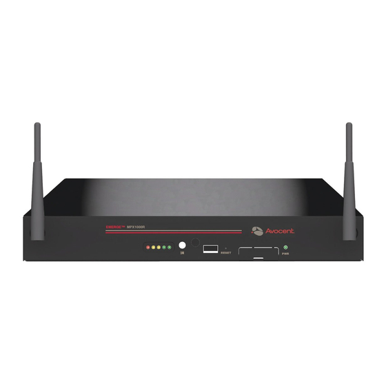
Page 27: Figure 2.1: Emerge Mpx1000 Transmitter (Front)
CHAPTER Hardware Overview Transmitter The transmitter encodes, compresses and sends media signals from a source device to a group of bound receivers. The following sections provide an overview of MPX1000 and MPX1500 transmitters. MPX1000 transmitter overview Table 2.1 provides an overview of the MPX1000 transmitter. Omni-directional Antenna IR Receiver... -
Page 28: Figure 2.2: Emerge Mpx1000 Transmitter (Rear)
The dual IR(tx) emitter connects to this port via a 3.5mm jack Omni-directional Antenna Used to establish the wireless link between the transmitter and bound receivers; Avocent offers specialized antennas for improved distance or higher performance in certain bands. See the Avocent web site for more information. -
Page 29: Mpx1500 Transmitter Overview
Chapter 2: Hardware Overview Table 2.2: Rear Panel (Transmitter) (Continued) Item Description Serial Port RS-232, 9-pin serial port to support serial passthrough for control of display devices Power IEC power socket with built-in fuse and on/off switch USB Port USB Type B; reserved for future use Media Module Slot Open slot on rear;... -
Page 30: Figure 2.3: Emerge Mpx1500 Transmitter (Rear)
MPX Extender Installer/User Guide Power Toslink Serial Universal Audio Audio A/V Port Figure 2.3: Emerge MPX1500 Transmitter (Rear) Table 2.3: Rear Panel (MPX1500 Transmitter) Item Description Power DC power input port Serial Port RJ45 connector for attachment of optional DB9-UNI or DB9-DUAL adapter. -
Page 31: Figure 2.4: Emerge Mpx1000 Receiver (Front)
The dual IR(tx) emitter connects via the 3.5mm jack Omni-directional Antenna Used to establish the wireless link between the transmitter and bound receivers. Avocent offers specialized antennas for improved distance or higher performance in certain bands. See the Avocent web site for more information... -
Page 32: Figure 2.5: Emerge Mpx1000 Receiver (Rear)
MPX Extender Installer/User Guide Table 2.4: Front Panel ( (Continued)Receiver) (Continued) Item Description Status Lights Five colored LEDs that communicate the current state of the device. Located on the front panel in the following order (left to right): RED AMBER1 AMBER2 GREEN1 GREEN2 See MPX Status LEDs on page 69 for a detailed description of LED status indicators USB Port... -
Page 33: Figure 2.6: Emerge Mpx1500 Hd Multipoint Extender Receiver (Front)
The dual IR(tx) emitter connects via the 3.5mm jack Omni-directional Antenna Used to establish the wireless link between the transmitter and bound receivers. Avocent offers specialized antennas for improved distance or higher performance in certain bands. See the Avocent web site for more information... -
Page 34: Figure 2.7: Emerge Mpx1500 Hd Multipoint Extender Receiver (Rear)
MPX Extender Installer/User Guide Table 2.6: Front Panel ( (Continued)Receiver) (Continued) Item Description Status Lights Five colored LEDs that communicate the current state of the device. Located on the front panel in the following order (left to right): RED AMBER1 AMBER2 GREEN1 GREEN2 See MPX Status LEDs on page 69 for a detailed description of LED status indicators USB Port... -
Page 35: Mpx1000 Media Modules
Chapter 2: Hardware Overview Table 2.7: Rear Panel (Receiver) (Continued) Item Description Serial Port RJ45 connector for attachment of optional DB9-UNI or DB9- DUAL adapter. The dual adapter splits the port into two RS-232 DB9 female connectors. Supports serial passthrough for control of display devices. -
Page 36: Figure 2.8: Hdmi Media Module
MPX Extender Installer/User Guide Audio is limited to a single stream. HDMI embedded digital audio, if present, takes priority over analog audio. See Audio on page 73 for additional information. RCA Jacks Captive Screw (Unbalanced Audio) HDMI Type A Figure 2.8: HDMI Media Module Figure 2.8 illustrates an HDMI input media module. -
Page 37: Figure 2.9: Hd15 Media Module
Chapter 2: Hardware Overview Captive Screw RCA Jacks (Unbalanced Audio) 15-Pin HD female Connector Figure 2.9: HD15 Media Module Figure 2.9 illustrates an HD15 (VGA) input media module. The MPX1000 transmitter will sample analog audio signals received on the RCA jacks and send the data to all bound receivers. See Audio on page 73 for additional information. - Page 38 MPX Extender Installer/User Guide...
-
Page 39: Chapter 3: Installation
CHAPTER Installation Getting Ready To begin installing your Emerge MPX extenders, do the following: • Take proper precautions against antistatic discharge. • Remove your MPX transmitter, receivers, antennas and media modules (for MPX1000 transmitters or receivers) from their boxes. •... -
Page 40: Transmitter Configuration
AC line cord to the power supply and connect the DC power to the transmitter. Wait for the initialization sequence to complete: For MPX1000 transmitters: An Avocent logo will appear on the front panel display. For MPX1500 transmitters: Two green LEDs will alternate and all other LEDs will turn off. -
Page 41: Figure 3.1: Control Lan Settings
Chapter 3: Installation Type the subnet mask for L1. Type the gateway address for L1, or 0.0.0.0 if there is no gateway. 11. The LAN Speed / Duplex setting allows you manually select 10 or 100Mbps LAN speed and full or half duplex operation. By default, these settings will be automatically negotiated with your switch or hub. - Page 42 Auto-detection relies upon the state of ID bits that the transmitter reads from the attached video cable. When using Avocent cables or adapters, the transmitter will properly sense the type of source device. Use of third- party video cables will cause the transmitter to sense the cable type as DVI-D/HDMI.
-
Page 43: Figure 3.3: System Settings
Chapter 3: Installation Apply the changes. Figure 3.3: System Settings Validating media LAN connectivity Media session data (audio, video, and control information) is transferred from an MPX transmitter to bound receivers either through the wireless LAN interface or the L2 wired LAN interface. By default, MPX transmitters are configured for wireless operation. -
Page 44: Setting Explicit Receiver Bindings (Suggested)
MPX Extender Installer/User Guide share a single wired extension network. Skip to the next step if you are not planning to install multiple transmitters on the same wired media LAN. You may place more than one transmitter on a wired media LAN. To do so, select a unique Transmitter Number from the pull-down menu on the media LAN Settings web page. - Page 45 Chapter 3: Installation Requests from non-selected receivers will be rejected by the transmitter. This feature is referred to as explicit bindings. Explicit bindings offer the following benefits: • Loss of connection with dynamically bound receivers is not treated as an error condition by the transmitter.
-
Page 46: Figure 3.4: Bindings Page
All units should be at revision 1.2.1.x or greater. Visit the Avocent web site at www.avocent.com and review the available upgrades. Should you decide to upgrade your units, see Upgrading MPX Firmware on page 93 for detailed instructions. -
Page 47: Figure 3.5: Mpx1500 Receiver Display Device Settings
Chapter 3: Installation NOTE: MPX1000 receivers feature a dedicated control LAN port, which is labelled L1. MPX1500 receivers have a single LAN port that serves the combined functions of control LAN and media LAN. The combined LAN port on the MPX1500 receiver is programmed with two unique IP addresses, one for each function. By default, the transmitter forwards web traffic between its control LAN (L1) port and its media LAN (L2) port or wireless LAN interface (whichever is active). -
Page 48: Mpx1000 Receiver Display Device Settings
MPX Extender Installer/User Guide ID bits that the receiver reads from the attached video cable. When using Avocent cables or adapters, the receiver will always properly sense the type of source device. The receiver is also able work properly with directly-attached third-party DVI-D/HDMI or RGBHV video cables. -
Page 49: Figure 3.6: Mpx1000 Receiver Display Device Settings
Chapter 3: Installation NOTE: The MPX1000 Display Device Settings page is displayed only when an analog media module (HD15) is installed. Figure 3.6: MPX1000 Receiver Display Device Settings To configure MPX1000 receiver display device settings: Using a browser client, access the web interface of the MPX receiver either directly or via the transmitter web interface. -
Page 50: Mpx Receiver Control Lan (L1) Settings (Optional)
MPX Extender Installer/User Guide MPX receiver control LAN (L1) settings (Optional) To establish a dedicated wired control LAN for management of MPX extenders, it will be necessary to establish unique IP addresses for the control LAN ports (L1) of each receiver and transmitter to be placed on the shared LAN. -
Page 51: Multiple Transmitter Considerations
The Remote Console feature allows for centralized control of the MPX extenders that are deployed at remote locations. Contact Avocent technical support before you enable this feature. -
Page 52: Initiating A Media Session
MPX Extender Installer/User Guide Initiating A Media Session Your MPX extension network is now ready for a media session. The following steps allow you to verify proper operation of your transmitter, receivers, establish an Active EDID string at the MPX transmitter and test compatibility of your source and display devices through the extension network. -
Page 53: Transmitter And Receiver Placement
Chapter 3: Installation Transmitter and Receiver Placement To find acceptable locations for your extenders: Turn off all MPX extenders. Turn off your source and display devices. Place the transmitters and receivers in their desired locations without firmly mounting the units. Turn on the MPX extenders and raise antennas to their upright positions. - Page 54 MPX Extender Installer/User Guide radiate on a vertical plane. This may increase the benefit of antenna diversity by taking advantage of diverse reflections off of environmental objects such as walls, floors, desks, and ceilings. Use of lower frequency channels may slightly increase transmission distance and wall penetration.
-
Page 55: Figure 3.7: Bound Receiver Status
Chapter 3: Installation Figure 3.7: Bound Receiver Status Final Adjustments Presentation of audio and video media should now be active at each display device, as if they were each individually attached to the source device. Inspect each display for signs of hesitation, color shift, audio loss, or other anomalies. -
Page 56: Figure 3.8: Change Login Password Page
MPX Extender Installer/User Guide Figure 3.8: Change Login Password Page... -
Page 57: Chapter 4: Additional Functions
CHAPTER Additional Functions System Tuning Transmitter tuning parameters Controls provided on the Tuning Parameters web page, illustrated in Figure 4.1, allow you to fine tune the operation of your extension system. To properly tune the video data rate settings, it is helpful to understand that the bandwidth capacity of the wireless media LAN is continually shifting rather than constant. -
Page 58: Table 4.1: Transmitter Tuning Parameters - Basic Settings
MPX Extender Installer/User Guide The transmitter offers basic and advanced settings. The basic settings are described in the following table: Table 4.1: Transmitter Tuning Parameters - Basic Settings Setting Description Wireless Video Data Rate These settings allow the MPX transmitter to dynamically adjust the degree of compression applied to real-time video data. -
Page 59: Figure 4.1: Transmitter Tuning Parameters - Basic Settings
Under most conditions, these settings should not be required. Should the basic tuning parameters be insufficient to resolve issues in your environment, contact Avocent technical support for additional suggestions. Receiver tuning parameters The Tuning Parameter web page on MPX receivers, illustrated in Figure 4.2, allow fine... -
Page 60: Figure 4.2: Receiver Tuning Parameters
MPX Extender Installer/User Guide The following table provides an overview of receiver tuning parameters: Table 4.2: Receiver Tuning Parameters Setting Description Receiver Video Latency The MPX transmitter places a timestamp on audio and video data to ensure proper lip-synch across all bound receivers. Thus audio and video Receiver Audio Latency output will be synchronized across all display devices as long as the devices themselves introduce equivalent latency prior to display. -
Page 61: Table 4.3: Methods For Fine Tuning
Chapter 4: Additional Functions Fine tuning suggestions The following table provides detailed instructions for tuning your MPX extenders. Table 4.3: Methods for Fine Tuning If you are fine tuning... Then choose... choppy video for a wired or The Wireless Video Data Rate settings on the Tuning Parameters page wireless connection of the transmitter. - Page 62 Higher values allow for increased distances between transmitters and receivers. In addition, Avocent offers optional extended distance antennas for this purpose. The default power setting may overdrive radio receivers when MPX transmitters and receivers are positioned in close proximity to each other, within ten feet or less, as might be the case during initial configuration and testing.
-
Page 63: Figure 4.3: Transmitter Media Lan Settings
Chapter 4: Additional Functions Table 4.3: Methods for Fine Tuning (Continued) If you are fine tuning... Then choose... Audio video synchronization Receiver Video Latency and Receiver Audio Latency settings on the across display devices receiver Tuning Parameters web page. Figure 4.2 on page 46 illustrates these settings. - Page 64 MPX Extender Installer/User Guide available to the device attached to its serial port. Serial data is passed in real-time and is not buffered for subsequent reading. Serial passthrough modes are enabled via the web interface of an MPX transmitter. Serial port settings, such as baud rate, flow control, data size, stop bits and parity are also configurable only via the transmitter’s web interface.
-
Page 65: Figure 4.4: Serial Passthrough Mode
Chapter 4: Additional Functions Figure 4.4 illustrates the basic flow of serial data among MPX units and attached devices. Figure 4.4: Serial Passthrough Mode Use the Serial Passthrough parameters section on the transmitter’s Serial Settings page to specify the serial mode and settings. To configure serial passthrough modes: Select Serial Settings from the Transmitter Menu, located on the left side of the web page. -
Page 66: Figure 4.5: Serial Settings Page: Serial Parameters
MPX Extender Installer/User Guide Choose the serial data size for the local serial port from the Data Size drop-down list. Choose the number of serial stop bits for the local serial port from the Stop Bit drop-down list. Choose the serial parity for the local serial port from the Parity drop-down list. Choose the serial flow control for the local serial port from the Flow Control drop-down list. -
Page 67: Figure 4.6: Ir Flow: Transmitter To Receiver
A single IRB-100 dual emitter is supplied with the MPX transmitter. Should it be necessary to control more than two source devices, Avocent offers the IRB-Y splitter, which allows two IRB-100 dual emitters to be attached to a single MPX transmitter. Additional IRB-100 emitters may also be purchased separately. -
Page 68: Figure 4.7: Ir Flow: Primary Receiver To Transmitter
MPX Extender Installer/User Guide Figure 4.7: IR Flow: Primary Receiver to Transmitter... -
Page 69: Figure 4.8: Ir Loopback
Chapter 4: Additional Functions Figure 4.8 illustrates local looping of IR commands. This allows source or display devices to be controlled locally. Figure 4.8: IR Loopback NOTE: IR data looped locally within an MPX transmitter or the primary receiver will also be sent normally across the extension network. -
Page 70: Figure 4.9: Serial Settings Page: Ir Parameters
MPX Extender Installer/User Guide Figure 4.9: Serial Settings Page: IR Parameters Regardless of the IR blaster mode setting, all IR data received by the local IR receiver port on the transmitter is forwarded to all connected receivers. This IR data will be sent to the IR transmit port at each of those receivers. - Page 71 Chapter 4: Additional Functions Table 4.4: Status Page Information (Continued) Tx / Field Description Control LAN MAC Both L1 MAC address (control LAN) of the transmitter or receiver, also printed on an Address external label on the unit. Wired Media LAN L2 MAC address (media LAN) of the transmitter.
-
Page 72: Media Lan Performance
MPX Extender Installer/User Guide Table 4.4: Status Page Information (Continued) Tx / Field Description RGB Video Resolutions that are currently stored in the Active EDID string of the transmitter. Resolutions This field is present for VGA display devices only. Stored Signal Strength An indication of the wireless signal strength on the receiver unit. -
Page 73: Figure 4.10: System Reboot Page
Chapter 4: Additional Functions System Reboot The System Reboot page is displayed when you select Reboot from the transmitter or receiver main menu. The page provides status updates during the reboot process and provides a Reboot Now button. To reboot an extender: Click Reboot Now. -
Page 74: Figure 4.11: Reset To Factory Defaults Page
Figure 4.11: Reset to Factory Defaults Page MPX1000 Front Panel Display The MPX1000 transmitter displays an Initializing message during power-up, followed by the Avocent logo. Press any button while the Avocent logo is displayed to enter the menu display system. Display modes The front panel menu system has three major display modes: •... -
Page 75: Table 4.6: Buttons For Automatic Menu Display Mode
Chapter 4: Additional Functions Table 4.5: Buttons for Manual Menu Navigation (Continued) Button Description Down Scrolls down through a set of items within a menu. NOTE: While in this mode, the symbol is displayed in the upper left character position of the display to indicate that the Down button will scroll down to the next item in the menu. -
Page 76: Table 4.7: Buttons For Parameter Modification Mode
• Display Tx Settings • Configure Control LAN To scroll through these top level menu selections when the Avocent logo is present, press any of the four arrow buttons. To navigate through these items, press the buttons. To select Down and display a corresponding sub-menu, press the buttons. - Page 77 Chapter 4: Additional Functions • Primary status: The primary receiver is identified by the presence of Pri in the name display • Signal strength: reported by the receiver back to the transmitter • Frame rate Press the buttons to manually scroll through status for all receivers. Press the Down Right button to enter into a timed scrolling mode, which displays status of all receivers in a round robin...
-
Page 78: Screen Saver
Yes was selected and the settings were valid. Otherwise, the current configuration will not be altered. In either case, you will be returned to top level of the Configure Control LAN menu. Press the button to return to the Avocent logo or the buttons to scroll through the Left Down top level menu. -
Page 79: Appendix A: Technical Support
Appendix A: Technical Support Our technical support staff is ready to assist you with installation or functional issues that you may encounter with your Avocent product. If an issue should develop, follow the steps below for the fastest possible service. -
Page 80: Appendix B: Radio Considerations
When cables are necessary, use the shortest Avocent-certified cable that allows you to properly position your antenna. Daisy- chaining of antenna extension cables is not supported. Carefully follow installation instructions provided with your cable kit and properly configure the extender when using extension cables as described in “Antenna Options”... - Page 81 NOTE: Because antenna options have a direct impact on the effective radiated power of MPX extenders, it is important to use only Avocent-certified options. Furthermore, antenna options should be used only as described herein. Misuse of these options could result in excessive radiated power or degraded performance.
- Page 82 MPX Extender Installer/User Guide antenna from Avocent that is not specifically listed in the pull-down list, then select the generic antenna that most closely resembles the antenna that you have installed. High gain and directional antennas act to concentrate radio waves in a narrow beam or plane in the same way that a megaphone concentrates sound waves.
-
Page 83: Figure C.1: Mpx Led Status Indicators
If a Power On Self Test (POST) error occurs, a specific pattern will be displayed. Please make note of the pattern prior to contacting Avocent technical support. Wireless operation status If no connection exists, a 2-step searching pattern sequence is displayed, as follows: Search pattern: Green-1 and Green-2 will alternate, all other LEDs remain off. -
Page 84: Table C.1: Led Status - Wireless Connection
MPX Extender Installer/User Guide Table C.1: LED Status - Wireless Connection Signal Level Amber-1 Amber-2 Green-1 Green-2 Wired operation status If no connection exists, a 2-step searching pattern sequence is displayed, as follows: Search pattern: Green-1 and Green-2 will alternate, all other LEDS remain off. If a connection does exist, the current signal level (0-5) of the connection is displayed as follows: Table C.2: LED Status - Wired Connection Signal Level... -
Page 85: Table C.3: Led Status - Reset Button Press
Appendices Reset button status You may perform multiple levels of reset using the button on the front panel of the receiver. As you continue to hold the button the LED pattern will change, reflecting the action to be performed. The various LED patterns are described in the following table: Table C.3: LED Status - Reset Button Press All LEDs blinking or... -
Page 86: Figure C.2: Mpx Receiver Rear Led Status Indicators
MPX Extender Installer/User Guide ST-2 ST-1 Figure C.2: MPX Receiver Rear LED Status Indicators ST-1 operation: • Blinking: Indicates system boot • Solid Media LAN established ST-2 operation: • Off: Connection with transmitter is not established • Slow blink: Signal level = 1 •... -
Page 87: Appendix D: Audio
Appendices Appendix D: Audio The HDMI media module for MPX1000 extenders offers support for embedded digital audio and unbalanced analog audio via left and right RCA jacks. The HD15 media module supports only unbalanced analog audio. Analog audio is sampled at 48Khz, which is CD quality audio. NOTE: With MPX1000 units you have received two snap-on ferrites. -
Page 88: Figure E.1: Transmitter Status Table
MPX Extender Installer/User Guide Appendix E: Video Troubleshooting The following troubleshooting tips should help you to resolve most common setup and initialization issues. If your problem persists, please contact Avocent technical support for additional help. Available Information The Transmitter Status table, illustrated in Figure E.1, on the Connection Status page of an MPX transmitter offers additional information. -
Page 89: Figure E.2: Transmitter Media Lan Performance
Appendices Primary Video Resolutions: This field contains a list of all resolutions that the Primary Receiver has reported to the transmitter. These values would have come from the display device itself or from the Display Settings page of the receiver. Video Resolutions in Use: This field indicates the list of resolutions that have been reported to the source device. - Page 90 MPX Extender Installer/User Guide • Improper initial power sequence: It is possible that the source device obtained EDID information from the MPX transmitter before device information was obtained from the display device. To resolve this, follow the suggested power up sequence provided in “Ini- tiating A Media Session”...
- Page 91 Appendices • Initiate a video hot plug of the source and display devices to ensure that the EDID infor- mation has been read and transferred across the extension network. • Power cycle the transmitter to clear invalid HDCP keys, which may have been collected from a non-valid display device.
- Page 92 MPX Extender Installer/User Guide • If your source device is a desktop PC or server, then you must disconnect the MPX transmitter from its VGA port and connect a VGA monitor in its place. It may be necessary to reboot the computer to establish video. Change the resolution to 640 x 480 @ 60Hz.
-
Page 93: Figure F.1: Transmitter Rack Mount Brackets
VESA MIS-E compatible mounting, using third-party brackets as described below Table mounting The Avocent RMK-56 table mounting bracket kit is compatible with MPX1000 transmitters and receivers. The kit contains two brackets, which are interchangeable such that either may be used as a left or right bracket. -
Page 94: Figure F.2: Parts For Under Desk Mounting Option
MPX Extender Installer/User Guide Figure F.2: Parts for Under Desk Mounting Option The following diagram offers dimensions, in inches, of the RMK-56 horizontal mounting brackets when used in conjunction with the MPX1000R receiver. Figure F.3: Installing the Horizontal Mounting Bracket (Under Desk Option) NOTE: Mounting accessories are ordered separately. -
Page 95: Figure F.4: Mpx1500 Mounting Bracket
Appendices MIS-E standard is designed for mounting of mid-size displays that weigh under 50 pounds. Compliant products, such as the MPX1000 transmitter and receiver, are equipped with a 200 x 100mm mounting hole pattern. Please follow the mounting instructions provided with the third-party mounting kit. Mounting options for MPX1500 extenders Wall and table mounting An optional keyhole style mounting bracket (part number DMK-04) is available for use with... -
Page 96: Figure F.5: Mpx1500 Power Supply Bracket
MPX Extender Installer/User Guide Power Supply Bracket An optional power supply bracket kit (part number PBK-01) is available for MPX1500 extenders. This bracket may be used to affix to the external power adapter to the chassis of the MPX1500 extender. Figure F.5: MPX1500 Power Supply Bracket To install the power supply bracket: Using the screw provided, attach the bracket to the side of the MPX1500 chassis. -
Page 97: Table G.1: Mpx1000T Hd Multipoint Extender Product Specifications
Appendices Appendix G: Technical Specifications Table G.1: MPX1000T HD Multipoint Extender Product Specifications Physical Attributes Height 1.7" Width 17" Depth 7.54" Ambient Atmospheric Condition Ratings Operating Temperature 32F - 118.4 F (0C - 48C) Storage Temperature -04F - 140F (-20C- 60C) 20% to 80% relative humidity (non-condensing) across the operating Humidity temperature range... -
Page 98: Table G.2: Mpx1000R Hd Multipoint Extender Product Specifications
MPX Extender Installer/User Guide Table G.1: MPX1000T HD Multipoint Extender Product Specifications (Continued) Standards FCC Class B, UL, cUL, RoHS, CE, ICES-003, WEEE Supported Radio Bands UNII 1: (4 channels) 5.15-5.25 GHz UNII 3: (4 channels) 5.725 to 5.825 GHz ISM (11 channels) 2.412 to 2.462 GHz (supported in USA only) -
Page 99: Table G.3: Mpx1000T Hdmi Input Module Product Specifications
800 x 600 @ 60Hz 1280x720 @ 60Hz 1280x768 @ 60Hz* 1360x768 @ 60Hz* * Support for these resolutions may require a hardware upgrade. Contact Avocent HDMI A/V input Port technical support for details. SD video resolutions: (at 30 frames per second) -
Page 100: Table G.4: Mpx1000R Hdmi Output Module Product Specifications
800 x 600 @ 60Hz 1280x720 @ 60Hz 1280x768 @ 60Hz* 1360x768 @ 60Hz* * Support for these resolutions may require a hardware upgrade. Contact Avocent HDMI A/V Output Port technical support for details. SD video resolutions: (at 30 frames per second) -
Page 101: Table G.5: Mpx1000T Hd15 (Vga) Input Module Product Specifications
800 x 600 @ 60Hz 1280x720 @ 60Hz 1280x768 @ 60Hz* 1360x768 @ 60Hz* * Support for these resolutions may require a hardware upgrade. Contact Avocent technical support for details. SD video (VGA) resolutions: (at 30 frames per second) 480p @ 60Hz... -
Page 102: Table G.6: Mpx1000R Hd15 (Vga) Output Module Product Specifications
MPX Extender Installer/User Guide Table G.5: MPX1000T HD15 (VGA) Input Module Product Specifications (Continued) (Continued) The Analog audio frequency response: 20Hz-20Khz with a 3dB per octave roll-off Frequency Response beginning at 14 kHz Regulatory Compliance (Compliance Model Number (CMN): 2003 Series) Standards FCC Class B, UL, cUL, RoHS, CE, ICES-003, WEEE Table G.6: MPX1000R HD15 (VGA) Output Module Product Specifications... - Page 103 Appendices Table G.7: MPX1500(T/R) HD Multipoint Extender Product Specifications (Continued) Width 6.92" Depth 4.55" Ambient Atmospheric Condition Ratings Operating Temperature 32F - 118.4 F (0C - 48C) Storage Temperature -04F - 140F (-20C- 60C) 20% to 80% relative humidity (non-condensing) across the operating Humidity temperature range Altitude 10,000 ft across the operating temperature range, 35,000 ft across storage...
- Page 104 MPX Extender Installer/User Guide Table G.7: MPX1500(T/R) HD Multipoint Extender Product Specifications (Continued) Supports the following VGA video resolutions: Computer (VGA) resolutions: (at 30 frames per second) 640 x 480 @ 60Hz 800 x 600 @ 60Hz 1280x720 @ 60Hz 1280x768 @ 60Hz Video Resolutions 1360x768 @ 60Hz...
- Page 105 Appendices Table G.7: MPX1500(T/R) HD Multipoint Extender Product Specifications (Continued) Analog audio frequency response: 20Hz-20Khz with a 3dB per octave roll-off Frequency response beginning at 14 kHz Regulatory Compliance (Compliance Model Number (CMN): 2003 Series) Standards FCC Class B, UL, cUL, RoHS, CE, ICES-003, WEEE Supported Radio Bands UNII 1: (4 channels) 5.15-5.25 GHz...
-
Page 106: Table H.1: Firmware And Hardware Versions Page Information
MPX Extender Installer/User Guide Appendix H: Displaying Firmware and Hardware Versions The Firmware and Hardware Versions page is used to display the firmware and hardware version numbers. This page is the same for transmitters or receivers. To display version information: Select Version Information from the Transmitter Menu or Receiver Menu, located on the left side of the web page. -
Page 107: Appendix I: Upgrading Mpx Firmware
Appendices Appendix I: Upgrading MPX Firmware NOTE: You must have access to a TFTP server to perform the Flash update process. The Flash Update page is used to download and install new firmware. All of the steps in this process and the web pages are the same for a transmitter and receivers. The Flash update process goes through several different stages. - Page 108 MPX Extender Installer/User Guide To install the Flash update: Check the version numbers and decide whether you want to proceed with the Flash update. Click Install Image to start the Flash update process, or click Cancel to return to the main Flash Update page.
- Page 109 Appendices Flash update progress The web page shows the update progress and a percent complete for each of the Flash update steps. The web page updates every three seconds. Press Cancel, if necessary, to return to the main Flash Update page. Do not turn off the unit because it may not recover. NOTE: Flash update steps for Erase boot region and Write boot image do not occur if the current boot version and the new boot version are the same.
- Page 110 MPX Extender Installer/User Guide Flash update errors A Flash update error may occur at any state. An error message is displayed. Click Restart to try again.
-
Page 111: Table J.1: Mpx Extender Supported Iso Country Codes
Appendices Appendix J: Supported ISO Country Codes Table J.1: MPX Extender Supported ISO Country Codes Country ISO Code North America United States Canada Europe Austria Belgium Cyprus Czech Republic Denmark Estonia Finland France Germany Greece Hungary Ireland Italy Latvia Lithuania Luxembourg Malta Netherlands... - Page 112 MPX Extender Installer/User Guide Table J.1: MPX Extender Supported ISO Country Codes (Continued) Country ISO Code Portugal Russia Slovakia Slovenia Spain Sweden Switzerland Turkey Asia / Pacific Australia China (PRC) Hong Kong India Indonesia Japan Korea Malaysia New Zealand Philippines Singapore Taiwan Africa / Middle East...
- Page 113 Appendices Table J.1: MPX Extender Supported ISO Country Codes (Continued) Country ISO Code Brazil Mexico...
-
Page 114: Table K.1: Mpx1000 Transmitter Kit Contents
MPX Extender Installer/User Guide Appendix K: Kit Contents Table K.1: MPX1000 Transmitter Kit Contents Part Number Description MPX1000T MPX transmitter IRB-100 Dual IR blaster 038-0208-5 2 omni-directional antennas 570-1390-501 2 rack mount brackets Varies by region Line cord 590-645-501x Quick Installation Guide Table K.2: MPX1000 Receiver Kit Contents Part Number Description... -
Page 115: Table K.5: Mpx1000 Receiver Vga Media Module Kit Contents
Appendices Table K.5: MPX1000 Receiver VGA Media Module Kit Contents Part Number Description MPX1000MR-HD15 Receiver media module Table K.6: MPX1000 Transmitter VGA Media Module Kit Contents Part Number Description MPX1000MT-HD15 Transmitter media module Table K.7: MPX1500 Transmitter / Receiver Kit Contents Part Number Description MPX1500... - Page 116 MPX Extender Installer/User Guide...
- Page 117 INDE X A/V signals 1 Input media module 4 Accessories 7 Installing, media module 25 Active EDID 3 Audio Considerations 73 Latency 2 Lip sync 2 Benefits, MPX1000 Extender product 2 Bound receiver 3 Main menu, front panel display 62 Media module 4, 19, 25 Configuration, transmitter 26 Media module, HD15 22...
- Page 118 MPX Extender Installer/User Guide Status 56 System configuration diagram 3 Universal A/V port 5 User interfaces 6 Transmitter 5, 13 Transmitter Number 5 Web-based interface 6 Wired link 5 Wireless link 5...
- Page 120 For Technical Support: www.avocent.com/support 590-671-501G...