Toshiba TOSVERT VF-S11 Instruction Manual
Industrial inverter for 3-phase induction motors
Hide thumbs
Also See for TOSVERT VF-S11:
- Instruction manual (269 pages) ,
- Option instruction manual (22 pages) ,
- Specifications (12 pages)
Table of Contents
Advertisement
Quick Links
Industrial Inverter
For 3-phase induction motors
Instruction Manual
TOSVERT
1-phase 240V class 0.2
3-phase 240V class 0.4
3-phase 500V class 0.4
3-phase 600V class 0.75
1.Make sure that this instruction manual is delivered to the
end user of the inverter unit.
2.Read this manual before installing or operating the inverter
unit, and store it in a safe place for reference.
S11
VF-
TM
2.2kW
15kW
15kW
15kW
NOTICE
E6581158
I
Safety
precautions
II
Introduction
Contents
1
Read first
2
Connection
3
Operations
4
Basic VF-S11
operations
5
Basic
parameters
6
Extended
parameters
7
Applied
operation
8
Monitoring the
operation status
9
Measures
to satisfy the
standards
10
Peripheral
devices
11
Table of
parameters
and data
12
Specifications
13
Before making
a service call
14
Inspection and
maintenance
15
Warranty
16
Disposal of the
inverter
2004 Ver. 108/109
Advertisement
Table of Contents

Related Manuals for Toshiba TOSVERT VF-S11


Summary of Contents for Toshiba TOSVERT VF-S11
-
Page 1: Industrial Inverter
E6581158 Safety precautions Introduction Contents Industrial Inverter Read first For 3-phase induction motors Connection Operations Instruction Manual Basic VF-S11 operations Basic parameters TOSVERT Extended parameters Applied operation Monitoring the operation status Measures to satisfy the standards 1-phase 240V class 0.2 2.2kW Peripheral 3-phase 240V class 0.4... -
Page 2: Safety Precautions
E6581158 Safety precautions The items described in these instructions and on the inverter itself are very important so that you can use the inverter safely, prevent injury to yourself and other people around you as well as to prevent damage to property in the area. -
Page 3: General Operation
E6581158 General Operation Danger See item • Never disassemble, modify or repair. This can result in electric shock, fire and injury. For repairs, call your sales distributor. Disassembly prohibited • Never remove the front cover when power is on or open door if enclosed in a cabinet. The unit contains many high voltage parts and contact with them will result in electric shock. - Page 4 Operation cannot be stopped immediately by the inverter alone, thus risking an accident or injury. • All options used must be those specified by Toshiba. 1.4.4 The use of any other option may result in an accident.
- Page 5 E6581158 Danger See item • Electrical installation work must be done by a qualified expert. Connection of input power by someone who does not have that expert knowledge may result in fire or electric shock. • Connect output terminals (motor side) correctly. If the phase sequence is incorrect, the motor will operate in reverse and that may result in injury.
-
Page 6: Maintenance And Inspection
E6581158 Warning See item • Observe all permissible operating ranges of motors and mechanical equipment. (Refer to the motor's instruction manual.) Not observing these ranges may result in injury. Prohibited When sequence for restart after a momentary failure is selected (inverter) Warning See item •... - Page 7 E6581158 Disposal Warning See item • If you throw away the inverter, have it done by a specialist in industry waste disposal(*). If you throw away the inverter by yourself, this can result in explosion of capacitor or produce noxious gases, resulting in injury. (*) Persons who specialize in the processing of waste and known as "industrial waste product collectors and transporters"...
-
Page 8: Industrial Inverter
3. Superior basic performance 200% or more starting torque Smooth operation : Reduced rotation ripple through the use of Toshiba's unique waveform formation. Built-in current surge suppression circuit : Can be safely connected even if power load is low. Maximum 500Hz high frequency output : Optimum for use with high speed motors such as those in lumber machinery and milling machines. -
Page 9: Table Of Contents
E6581158 Contents Safety precautions .................................1 Introduction ..................................7 1. Read first..................................A-1 Check product purchase ............................A-1 Contents of the product............................A-2 Names and functions ............................A-3 Notes on the application.............................A-12 2. Connection..................................B-1 Cautions on wiring..............................B-1 Standard connections ............................B-2 Description of terminals............................B-5 3. Operations ..................................C-1 Simplified operation of the VF-S11........................C-2 How to operate the VF-S11 ..........................C-6 4. - Page 10 E6581158 Input signal selection ............................F-4 Terminal function selection ..........................F-7 Basic parameters 2............................F-16 Frequency priority selection..........................F-17 Operation frequency ............................F-25 DC braking................................. F-26 Auto-stop in case of lower-limit frequency continuous operation ............... F-28 Jog run mode..............................F-29 6.10 Jump frequency-jumping resonant frequencies ....................
- Page 11 E6581158 11.2 Basic parameters ...............................K-1 11.3 Extended parameters............................K-4 12. Specifications.................................L-1 12.1 Models and their standard specifications ......................L-1 12.2 Outside dimensions and mass ...........................L-4 13. Before making a service call - Trip information and remedies..................M-1 13.1 Trip causes/warnings and remedies........................M-1 13.2 Restoring the inverter from a trip........................M-5 13.3 If the motor does not run while no trip message is displayed................M-6...
-
Page 12: Read First
E6581158 1. Read first Check product purchase Before using the product you have purchased, check to make sure that it is exactly what you ordered. Warning Use an inverter that conforms to the specifications of power supply and three-phase induction motor being used. -
Page 13: Contents Of The Product
E6581158 Contents of the product Explanation of the name plate label. Type Form V F S 11 S - 2 0 0 7 P L E - W N - A 2 2 Applicable motor Default interface Special specification code Model name Input (AC) voltage Additional functions I... -
Page 14: Names And Functions
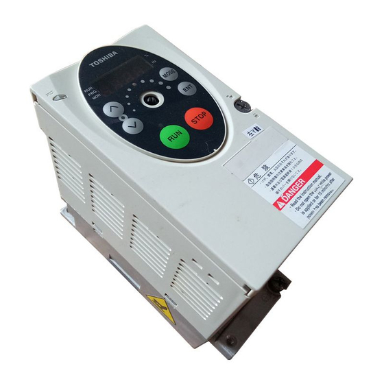
E6581158 Names and functions 1.3.1 Outside view RUN lamp Percent (%) lamp Lights when an ON command is issued but Lights when a numeric no frequency signal is sent out. It blinks value is displayed in %. when operation is started. PRG lamp Hertz (Hz) lamp Lights when the inverter... -
Page 15: Name Plate
E6581158 Unlock position mark The front panel is unlocked when Charge lamp the dot on the locking screw is on this (upper) side. Indicates that high voltage is still present within the inverter. Do not open the terminal board cover Front panel locking screw while this is lit. - Page 16 E6581158 Example of the label 40˚C 50mm 1.3.2 Power circuit and control circuit terminal boards In case of the lug connector, cover the lug connector with insulated tube, or use the insulated lug connector. Note 1: EMC plate is supplied as standard. 1) Power circuit terminal board In case of the lug connector, cover the lug connector with insulated tube, or use the insulated lug connector.
- Page 17 E6581158 VFS11-2015 ∼ 2037PM R/L1 S/L2 T/L3 M3.5 screw (2015 only) M4 screw (2022, 2037) PA/+ PC/− U/T1 V/T2 W/T3 Shorting-bar Grounding terminal (M5 screw) Screw hole for EMC plate Note 1 VFS11S-2002 ∼ 2007PL R/L1 S/L2 Grounding capacitor M3.5 screw disconnecting switch (See page A-9) PA/+...
- Page 18 E6581158 VFS11S-2015, 2022PL Grounding capacitor R/L1 S/L2 disconnecting switch M4 screw (See page A-9) PA/+ PC/− U/T1 V/T2 W/T3 Shorting-bar Grounding terminal (M5 screw) Screw hole for EMC plate Note 1 VFS11-4004 ∼ 4037PL, 6007 ∼ 6037P Grounding capacitor R/L1 S/L2 T/L3 disconnecting switch...
- Page 19 E6581158 VFS11-2055, 2075PM -4055, 4075PL, 6055, 6075P Grounding capacitor disconnecting tap M4 screw (See page A-9) (4055, 4075 only) M5 screw R/L1 S/L2 T/L3 PC/− U/T1 V/T2 W/T3 PA/+ Shorting-bar Grounding terminal Screw hole for EMC plate (M5 screw) Note 1 VFS11-2110, 2150PM -4110, 4150PL, 6110, 6150P Grounding capacitor...
- Page 20 E6581158 2) Grounding capacitor disconnecting switch and taps Warning The grounding capacitor disconnecting tap is provided with a protection cover. To avoid shock hazards, always attach the cover after connecting or disconnecting the capacitor to or from the tap. Mandatory Every single-phase 240V/three-phase 500V model has a built-in high-attenuation noise filter, which is grounded through a capacitor.
- Page 21 E6581158 3) Control circuit terminal board The control circuit terminal board is common to all equipment. SOURCE SINK OUT NO FM CC FLA FLB FLC RY RC FM VIA PLC S1 M3 screw PP VIA VIB CC (0.5N m) R RES CC Optional connector (RJ45) Wire size...
- Page 22 E6581158 1.3.3 How to open the front (terminal board) cover To wire the terminal board, remove the front lower cover in line with the steps given below. Turn the locking screw on the right side of the front panel 90˚ Pull the front panel toward you counterclockwise to align the dot on the screw with the unlock and swing it open to the left.
-
Page 23: Notes On The Application
E6581158 Notes on the application 1.4.1 Motors When the VF-S11 and the motor are used in conjunction, pay attention to the following items. Warning Use an inverter that conforms to the specifications of power supply and three-phase induction motor being used. If the inverter being used does not conform to those specifications, not only will the three- phase induction motor not rotate correctly, but it may cause serious accidents through overheating and Mandatory fire. - Page 24 E6581158 Low loads and low inertia loads The motor may demonstrate instability such as abnormal vibrations or overcurrent trips at light loads of 50 % or under of the load percentage, or when the load's inertia moment is extremely small. If that happens reduce the carrier frequency.
- Page 25 E6581158 Braking motor When using a braking motor, if the braking circuit is directly connected to the inverters's output terminals, the brake cannot be released because of the lowered starting voltage. Therefore, when using a braking motor, connect the braking circuit to the inverter's power supply side, as shown in the figure below.
- Page 26 E6581158 Power factor correction capacitor Power factor correction capacitors cannot be installed on the output side of the inverter. When a motor is run that has a power factor correction capacitor attached to it, remove the capacitors. This can cause inverter malfunction trips and capacitor destruction.
-
Page 27: What To Do About The Leak Current
E6581158 Disposal If an inverter is no longer usable, dispose of it as industrial waste. 1.4.3 What to do about the leak current Warning Current may leak through the inverter's input/output wires because of insufficient electrostatic capacity on the motor with bad effects on peripheral equipment. - Page 28 E6581158 (2) Affects of leakage current across lines Thermal relays Inverter Power supply Leakage current path across wires Thermal relays The high frequency component of current leaking into electrostatic capacity between inverter out- put wires will increase the effective current values and make externally connected thermal relays operate improperly.
-
Page 29: Installation Environment
E6581158 CT and ammeter If a CT and ammeter are connected externally to detect inverter output current, the leak current's high frequency component may destroy the ammeter. If the wires are more than 50 meters long, it will be easy for the high frequency component to pass through the externally connected CT and be superimposed on and burn the ammeter with models having motors of low rated current (several A(ampere) or less), especially the 500V and 600V class low capacity (3.7kW or less) models, because the leak current will increase in proportion to the motor's rated current. - Page 30 E6581158 Warning • Avoid operation in any location where there is direct spraying of the following solvents or other chemicals. The plastic parts may be damaged to a certain degree depending on their shape, and there is a possibility of the plastic covers coming off. If the chemical or solvent is anything other than those Prohibited shown below, please contact us in advance.
- Page 31 Operation cannot be stopped immediately by the inverter alone, thus risking an accident or injury. • All options used must be those specified by Toshiba. The use of any other option may result in an accident.
- Page 32 E6581158 Install the inverter in a well-ventilated indoor place and mount it on a flat metal plate in portrait orientation. If you are installing more than one inverter, the separation between inverters should be at least 5 centimeters, and they should be arranged in horizontal rows. If the inverters are horizontally arranged with no space between them (side-by-side installation), peel off the ventilation seals on top of the inverter.
- Page 33 E6581158 Calorific Values Operating motor Amount of forcible air Heat discharge surface Carrier Carrier Voltage class capacity Inverter type cooling ventilation area required for sealed frequency frequency required (m /min) storage cabinet(m (kW) 4kHz 12kHz 2002PL 0.15 0.52 2004PL 0.25 0.88 Single-phase 0.75...
- Page 34 E6581158 • Install EMC plate and use shielded wires. EMC plate Installing more than one unit in a cabinet If you are installing two or more inverters in one cabinet, pay attention to the following. • Inverters may be installed side by side with each other with no space left between them. •...
-
Page 35: Connection
E6581158 2. Connection Danger • Never disassemble, modify or repair. This can result in electric shock, fire and injury. For repairs, call your sales agency. Disassembly prohibited • Don't stick your fingers into openings such as cable wiring hole and cooling fan covers. This can result in electric shock or other injury. -
Page 36: Standard Connections
E6581158 Danger • Ground must be connected securely. If the ground is not securely connected, it could lead to electric shock or fire when a malfunction or current leak occurs. Be Grounded Warning • Do not attach devices with built-in capacitors (such as noise filters or surge absorber) to the output (motor side) terminal. -
Page 37: Standard Connection Diagram
E6581158 2.2.1 Standard connection diagram 1 This diagram shows a standard wiring of the main circuit. Standard connection diagram - SINK (Negative) (common:CC) DC reactor (DCL) Braking resistor (option) *2 (option) PA/+ PC/- Motor MCCB Main circuit power supply U/T1 R/L1 240V class: three-phase 200-240V S/L2... - Page 38 E6581158 2.2.2 Standard connection diagram 2 Standard connection diagram - SOURCE (Positive) (common:P24) Braking resistor (option) DC reactor (DCL) *2 (option) PA/+ PC/- Motor MCCB Main circuit power supply U/T1 R/L1 240V class: three-phase 200-240V S/L2 Noise V/T2 -50/60Hz Power circuit filter T/L3 W/T3...
-
Page 39: Description Of Terminals
E6581158 Description of terminals 2.3.1 Power circuit terminals This diagram shows an example of wiring of the main circuit. Use options if necessary. Power supply and motor connections Power supply VF-S11 Power lines are Motor lines are connected to R/L1, S/L2 and T/L3. connected to U/T1, V/T2 and W/T3. -
Page 40: Control Circuit Terminals
E6581158 Power circuit Terminal symbol Terminal function Grounding terminal for connecting inverter. There are 3 terminals in total. 2 terminals in the terminal board, 1 terminal in the cooling fin. 240V class: single-phase 200 to 240V-50/60Hz three-phase 200 to 240V-50/60Hz 500V class: three-phase 380 to 500V-50/60Hz R/L1,S/L2,T/L3 600V class: three-phase 525 to 600V-50/60Hz... - Page 41 E6581158 Terminal Electrical Input/output Function Inverter internal circuits symbol specifications Common to Control circuit's equipotential terminal (3 Input/output terminals) +24V 10Vdc Voltage Output Analog power supply output (permissible load conversion current: 10mA) 0.47 Multifunction programmable analog input. Factory default setting: 0~10Vdc and 0~60Hz (0~50Hz) frequency input.
- Page 42 E6581158 Terminal Electrical Input/output Function Inverter internal circuits symbol specifications +24V Output 24Vdc power output 24Vdc-100mA Multifunction programmable open collector Open collector output output. Standard default settings detect 24Vdc-50mA and output speed reach signal output frequencies. To output pulse Multifunction output terminals to which two trains, different functions can be assigned.
- Page 43 E6581158 SINK (Negative) logic/SOURCE (Positive) logic (When the inverter's internal power supply is used) Current flowing out turns control input terminals on. These are called sink logic terminals. (Type: -AN/-WN). The general used method in Europe is source logic in which current flowing into the input terminal turns it on (Typ: -WP).
- Page 44 E6581158 SINK (Negative) logic/SOURCE (Positive) logic (When an external power supply is used) The PLC terminal is used to connect to an external power supply or to insulate a terminal from other input or output terminals. As for input terminals, turn the SW1 slide switch to the PLC position. <Examples of connections when an external power supply is used>...
- Page 45 E6581158 ✩ The figure on the right shows an example of the connection of input terminals VIA and VIB when they are used as contact input terminals. This example 4.7kΩ illustrates the connection when the inverter is used in VIA(VIB) sink (Negative) logic mode.
-
Page 46: Operations
E6581158 3. Operations Danger • Do not touch inverter terminals when electrical power is going to the inverter even if the motor is stopped. Touching the inverter terminals while power is connected to it may result in electric shock. Prohibited •... -
Page 47: Simplified Operation Of The Vf-S11
E6581158 Simplified Operation of the VF-S11 The procedures for setting operation frequency and the methods of operation can be selected from the following. : (1) Start and stop using the operation panel keys Start / Stop (2) Run and stop from the operation panel : (1) Setting using the potentiometer on the inverter Setting the frequency main unit... - Page 48 E6581158 3.1.1 How to start and stop [Example of a setting procedure] Key operated LED display Operation Displays the operation frequency (operation stopped). (When standard monitor display selection = [Operation frequency]) Displays the first basic parameter [History ( MODE Press either the key to select “...
- Page 49 E6581158 3.1.2 How to set the frequency [Example of a setting procedure] Key operated LED display Operation Displays the operation frequency (operation stopped). (When standard monitor display selection = [Operation frequency]) Displays the first basic parameter [History ( MODE Press either the key or key to select “...
-
Page 50: Frequency Setting
E6581158 (3) Setting the frequency using the operation panel ( Frequency setting Setting the frequency using external potentiometer Potentiometer Setting frequency using the potentiometer (1-10kΩ, 1/4W) For more detailed information on adjustments, see 6.5. : Setting frequency 60Hz using potentiometer Frequency * The input terminal VIA can be used in the same way. -
Page 51: How To Operate The Vf-S11
E6581158 How to operate the VF-S11 Overview of how to operate the inverter with simple examples. Setting the operation frequency using built-in potentiometer and Ex.1 running and stopping using the operation panel. Wiring PA/+ PC/- Motor MCCB R/L1 U/T1 S/L2 V/T2 Noise Power circuit... - Page 52 E6581158 Setting the operation frequency using the operation panel and Ex.2 running and stopping using the operation panel. Wiring PA/+ PC/- Motor MCCB R/L1 U/T1 S/L2 V/T2 Noise Power circuit T/L3 filter W/T3 Braking circuit Parameter setting Title Function Programmed value Command mode selection Frequency setting mode selection 1 Operation...
- Page 53 E6581158 Setting the operation frequency using built-in potentiometer and Ex.3 running and stopping using external signals. Wiring PA/+ PC/- Motor MCCB R/L1 U/T1 S/L2 V/T2 Noise Power circuit filter T/L3 W/T3 Braking Run forward circuit signal backward signal Common Parameter setting Title Function Programmed value...
- Page 54 E6581158 Operation frequency setting, running and stopping using external Ex.4 signals. Wiring PA/+ PC/- Motor MCCB R/L1 U/T1 S/L2 V/T2 Noise Power circuit T/L3 W/T3 filter Run forward signal Braking circuit Run backward signal Common Current signal: 4∼20mA Voltage signal: 0∼10V External potentiometer (Otherwise, input voltage signal (0~10V) between the terminals VIA-CC.) Parameter setting...
-
Page 55: Basic Vf-S11 Operations
E6581158 4. Basic VF-S11 operations The VF-S11 has the following four monitor modes. : The standard inverter mode. This mode is enabled when Standard monitor mode inverter power goes on. This mode is for monitoring the output frequency and setting the frequency designated value. -
Page 56: Flow Of Status Monitor Mode
E6581158 Flow of status monitor mode Flow of monitor as following Status monitor mode Setting monitor mode f60.0 MODE MODE Standard monitor mode 60.0 28 kinds of data Display mode fr-f (See page D-1.) t0.10 MODE n<> 10 kinds of data Data of 4 times. -
Page 57: How To Set Parameters
E6581158 How to set parameters The standard default parameters are programmed before the unit is shipped from the factory. Parameters can be divided into 4 major categories. Select the parameter to be changed or to be searched and retrieved. : The basic parameters that must be programmed Basic parameters before the first use. - Page 58 E6581158 4.2.1 How to set the basic parameters All of the basic parameters can be set by the same step procedures. [Steps in key entry for basic parameters] * Parameters were factory-set by default Switches to the setting monitor mode. MODE before shipment.
-
Page 59: How To Set Extended Parameters
E6581158 4.2.2 How to set extended parameters The VF-S11 has extended parameters to allow you to make full use of its functions. All extended parameters are expressed with and three digits. Basic parameters ∼ MODE Press the key or the key to Press the MODE key once and use the change the set value. - Page 60 E6581158 Example of parameter setting Steps in setting are as follows (Example of changing the dynamic braking selection from 0 to 1.) Key operated LED display Operation Displays the operation frequency (operation stopped). (When standard monitor display selection [Operation frequency]) The first basic parameter “...
- Page 61 E6581158 Key operated LED display Operation Press the ENTER key to enable the user parameter automatic edit function. Searches for parameters that are different in value from the standard default setting and displays those parameters. Press the ENTER key or the key to change the parameter displayed.
- Page 62 E6581158 How to use the history function Key operated LED display Operation Displays the operation frequency (operation stopped). (When standard monitor display selection [Operation frequency]) The first basic parameter “ ” (history function) is displayed. MODE The parameter that was set or changed last is displayed. Press the ENTER key to display the set value.
- Page 63 E6581158 4.2.5 Parameters that cannot be changed while running For safety reasons, the following parameters have been set up so that they cannot be reprogrammed while the inverter is running. Stop operation (“0.0” or “off” is displayed) before changing parameter settings. [Basic parameters] (Automatic acceleration/deceleration) (Parameter setting macro torque boost)
- Page 64 E6581158 4.2.6 Returning all parameters to standard default setting Setting the standard default setting parameter = , all parameters can be returned to the those factory default settings. Note: For more details on the standard default setting parameter , see 5.6. Notes on operation •...
-
Page 65: Basic Parameters
E6581158 5. Basic parameters Before you operate the inverter, the parameters that you must first program are the basic parameters. Setting acceleration/deceleration time :Automatic acceleration/deceleration :Acceleration time 1 :Deceleration time 1 • Function 1) For acceleration time 1 programs the time that it takes for the inverter output frequency to go from 0Hz to maximum frequency 2) For deceleration time 1 programs the time that it takes for the inverter output frequency to got... - Page 66 E6581158 [Parameter setting] Title Function Adjustment range Default setting 0: Disabled (manual) Automatic acceleration/deceleration 1: Automatic 2: Automatic (only at acceleration) ✩ ✩ ✩ ✩ When automatically setting acceleration/deceleration time, always change the acceleration/deceleration time so that it conforms to the load. The acceleration/deceleration time changes constantly with load fluctuations.
-
Page 67: Increasing Starting Torque
E6581158 [Parameter setting] Title Function Adjustment range Default setting Acceleration time 1 0.0-3200 sec. 10.0 Deceleration time 1 0.0-3200 sec. 10.0 Note: When the acceleration/deceleration time is set at 0.0 seconds, the inverter speed increases or reduces speed within 0.05 seconds. ✩... - Page 68 E6581158 2) When using vector control (increasing starting torque and high-precision operations) (vector control + auto-tuning) Setting (vector control + auto-tuning) provides high starting torque bringing out the maximum in motor characteristics from the low-speed range. This suppresses changes in motor speed caused by fluctuations in load to provide high precision operation.
- Page 69 E6581158 (Torque boost setting macro function) and (V/F control mode selection) Automatic torque boost is the parameter for setting V/F control mode selection ( ) and auto-tuning ) together. That is why all parameters related to change automatically when is changed. Automatically programmed parameters Displays after resetting...
-
Page 70: Specifying An Operation Mode, Using Parameters
E6581158 Specifying an operation mode, using parameters : Parameter setting macro function • Function Automatically programs all parameters (parameters described below) related to the functions by selecting the inverter's operating method. The major functions can be programmed simply. [Parameter setting] Title Function Adjustment range... - Page 71 E6581158 Coast stop ( Setting for coast stopping. In sink logic mode, closing the circuit between the S3 and CC terminals places the inverter in standby mode and opening the circuit places it in coast stop mode, because ST (standby signal) is assigned to the S3 terminal.
- Page 72 E6581158 Output frequency Operation Forward run frequency command Operation frequency Reverse run command Powered Note 3 Note 2 External input UP/DOWN setting ( Allows setting of frequency with the input from an external contact. Can be applied to changes of frequencies from several locations.
-
Page 73: Selection Of Operation Mode
E6581158 Selection of operation mode : Command mode selection : Frequency setting mode selection 1 • Function These parameters are used to specify which input device (operation panel or terminal board) takes priority in entering an operation stop command or a frequency setting command (internal potentiometer, VIA, VIB, operation panel, serial communication device, external contact up/down, VIA+VIB). - Page 74 E6581158 [Programmed value] The internal potentiometer to the inverter is used for setting frequencies. Turning Potentiometer the notches clockwise raises the frequency. A frequency command is set by means of a signal from an external input device VIA input (VIA terminal: 0-10Vdc or 4-20mAdc). An external signal (VIB terminal: 0-10Vdc) is used to specify a frequency VIB input command.
-
Page 75: Meter Setting And Adjustment
E6581158 Meter setting and adjustment : Meter selection : Meter adjustment • Function The signal output from the FM terminal is an analog voltage signal. For the meter, use either a full-scale 0-1mAdc ammeter or full-scale 0-7.5Vdc (or 10Vdc-1mA) voltmeter. Switching to 0-20mAdc (4-20mAdc) output current can be made by turning the FM slide switch to the I position. - Page 76 E6581158 Resolution All FM terminals have a maximum of 1/1000. Example of 4-20mA output adjustment (for details, see 6.20.2) Output Output currrent currrent Internal calculated value Internal calculated value Note 1) When using the FM terminal for current output, be sure that the external load resistance is less than 750Ω. Note 2) Note that, if fmsl is set to 7 (torque), data will be updated at intervals of more than 40 ms.
- Page 77 E6581158 [Example of how to adjustment the FM terminal frequency meter] Use the meter's adjustment screw to pre-adjust zero-point. Key operated LED display Operation Displays the operation frequency. (When standard monitor display selection is set to [Operation frequency]) MODE The first basic parameter “ ”...
-
Page 78: Standard Default Setting
E6581158 Standard default setting : Default setting • Function Allows setting of all parameters to the standard default setting, etc. at one time. Note that fm, fmsl, f109, f470 ∼ f473, f669 and f880 will not be reset to their factory default settings. -
Page 79: Forward/Reverse Run Selection (Operation Panel Operation
E6581158 Save user setting parameters ( Setting saves the current settings of all parameters. (Refer to 4.2.7) Load user setting parameters ( Setting loads parameter settings to (calls up) those saved by setting . (Refer to 4.2.7) ✩ By setting , you can use parameters as your own default parameters. -
Page 80: Maximum Frequency
E6581158 The inverter was factory-configured by default so that shorting terminals F-CC and terminals R-CC simultaneously would cause the motor to slow down to a stop. Using parameter , however, you can choose between stop and reverse run. Using the parameter , however, you can select between forward run and reverse run. -
Page 81: Base Frequency
E6581158 Upper limit Lower limit Output frequency (Hz) frequency frequency Output frequency (Hz) 0 100% 0 100% Frequency setting signal Frequency setting signal * The output frequency * Frequencies that go cannot be set at less than higher than will not be output. Parameter setting Factory default Title... -
Page 82: Selecting Control Mode
E6581158 5.11 Selecting control mode : V/F control mode selection • Function With VF-S11, the V/F controls shown below can be selected. V/F constant Variable torque Automatic torque boost control *1 Vector control *1 Energy saving *1 Dynamic energy-saving (for fans and pumps) PM motor control (*1) Parameter setting macro torque boost:... - Page 83 E6581158 Warning: When setting the V/F control mode selection parameter (pt) to any number between 2 and 6, be sure to set at least the following parameters. (Motor rated current): See the motor's nameplate. (No-load current of motor): Refer to the motor test report. (Rated rotational speed of motor): See the motor's nameplate.
- Page 84 Motor constant must be set If the motor you are using is a 4P Toshiba standard motor and if it has the same capacity as the inverter, there is basically no need to set the motor constant. In any other case, be sure to set the parameters properly.
- Page 85 Motor constant must be set If the motor you are using is a 4P Toshiba standard motor and if it has the same capacity as the inverter, there is basically no need to set the motor constant. In any other case, be sure to set the parameters properly.
- Page 86 Motor constant must be set If the motor you are using is a 4P Toshiba standard motor and if it has the same capacity as the inverter, there is no need to set the motor constant. In any other case, be sure to set the parameters properly.
- Page 87 E6581158 Relationship between V/F control mode selection ( t) and Motor constant parameter & : Valid, : Invalid Parameter pt (V/F control mode selection) Variable Automatic Vector Energy- Dynamic Title Function constant torque torque boost control saving energy- control saving Torque boost setting macro function Base frequency 1...
-
Page 88: Manual Torque Boost - Increasing Torque Boost At Low Speeds
E6581158 5.12 Manual torque boost - increasing torque boost at low speeds : Torque boost 1 • Function If torque is inadequate at low speeds, increase torque by raising the torque boost rate with this parameter. Base frequency voltage Output frequency (Hz) Base frequency [Parameters] Title... - Page 89 E6581158 Parameter setting Title Function Adjustment range Default setting Motor electronic thermal 10 – 100 (%) / (A) protection level 1 Setting Overload Overload value protection stall × Standard motor × × Electronic-thermal protection × characteristic selection × VF motor (special ×...
- Page 90 E6581158 Setting of electronic thermal protection characteristics selection Setting value Overload protection Overload stall × × × × : valid, × : invalid Setting of motor electronic thermal protection level 1 (Same as f173) If the capacity of the motor is smaller than the capacity of the inverter, or the rated current of the motor is smaller than the rated current of the inverter, adjust the electronic thermal protection level 1 that it fits the motor's rated current.
- Page 91 E6581158 [Using a VF motor (motor for use with inverter)] Setting of electronic thermal protection characteristics selection Setting value Overload protection Overload stall × × × × : valid, × : invalid VF motors (motors designed for use with inverters) can be used in frequency ranges lower than those for standard motors, but their cooling efficiency decreases at frequencies below 6Hz.
-
Page 92: Preset-Speed Operation (Speeds In 15 Steps
E6581158 Inverter overload Time [sec] To protect the inverter, overload trip or overcurrent trip activate in 100% = inverter rated output current a short period of time when output current reaches 150% or higher. Output current [%] 110% 150% 200% Inverter overload protection characteristics 5.14 Preset-speed operation (speeds in 15 steps) : Preset-speed operation frequencies 1-7... - Page 93 E6581158 Setting from speed 8 to speed 15 Title Function Adjustment range Setting value Preset-speed operation frequencies f287- f294 (Hz) 8-15 Examples of preset-speed contact input signals: Slide switch SW1 set to sink logic O: ON -: OFF (Speed commands other than preset-speed commands are valid when all are OFF) Preset-speed Terminal S1-CC...
- Page 94 E6581158 Using other speed commands with preset-speed command Command mode selection 0: Terminal board 1: Operation panel 1: VIA 1: VIA 0: Built-in 2: VIB 4:Comm 0: Built-in 2: VIB Frequency setting 3: Operation 3: Operation 4:Commu potentio 5: UP/DOWN unicati potentio 5: UP/DOWN...
-
Page 95: Extended Parameters
E6581158 6. Extended parameters Extended parameters are provided for sophisticated operation, fine adjustment and other special purposes. Modify parameter settings as required. See Section 11, Table of extended parameters. Input/output parameters 6.1.1 Low-speed signal : Low-speed signal output frequency • Function When the output frequency exceeds the setting of an ON signal will be generated. - Page 96 E6581158 An example of the connection of the open collector OUT terminal An example of the connection of the relay output terminals +24V +24V • Output terminal setting Output of the low-speed signal (ON signal) between the RY and RC terminals is the factory default setting of the output terminal selection parameter.
- Page 97 E6581158 Output frequency [Hz] Designated frequency + Designated frequency Designated frequency − Set frequency speed reach signal Time [s] P24-OUT (Default setting) RY-RC FLA/FLC/FLB Set frquency spped reach signal: Inverted 6.1.3 Output of set frequency speed reach signal : Speed reach setting frequency : Speed reach detection band •...
-
Page 98: Input Signal Selection
E6581158 If the detection band value + the set frequency is less than the designated frequency Output frequency [Hz] Set frquency speed reach signal Time [s] RY-RO terminals P24-OUT terminals FLA-FLC-FLB terminals Set frequency speed reach signal: Inverted Input signal selection 6.2.1 Priority selection (both F-CC, R-CC are ON) : Priority selection (both F-CC, R-CC are ON) - Page 99 E6581158 (Stop)]: If an F command and an R command are entered simultaneously, the motor will slow down to a stop. Output frequency [Hz] Set frequency Forward run Time[s] Reverse run Run forward signal Run backward signal (Reverse)]: If an F command and an R command are entered simultaneously, the motor will run in the reverse direction.
- Page 100 E6581158 6.2.2 Changing the functions of VIA and VIB terminals : VIA/VIB terminal function selection • Function This parameter allows you to choose between signal input and contact signal input for the VIA and VIB terminals. Parameter setting Title Function Adjustment range Default setting 0: VIA - analog input...
-
Page 101: Terminal Function Selection
E6581158 Terminal function selection 6.3.1 Keeping an input terminal function always active (ON) : Always-active function selection 1 : Always-active function selection 2 • Function This parameter specifies an input terminal function that is always to be kept active (ON). Parameter setting Title Function... - Page 102 • Note that the setting 52 (forced operation) can be enabled only when the inverter is so configured at the factory. For more information, contact your local Toshiba dealer. • The functions of the VIB and VIA terminals can be selected between analog input and contact input by...
- Page 103 E6581158 Connection method 1) A-contact input Inverter Sink setting A-contact switch Input terminal * This function is activated when the input terminal and CC (common) are short- circuited. Use this function to specify forward/reverse run or a preset-speed operation. 2) Connection with transistor output Programmable controller Inverter * Operation can be controlled by connecting the...
-
Page 104: Modifying Output Terminal Functions
E6581158 3) Sink logic/source logic input Sink logic/source logic (input/output terminal logic) switching is possible. For more details, see 2.3.2. 6.3.3 Modifying output terminal functions : Output terminal selection 1A (RY-RC) : Output terminal selection 2A (OUT-NO) : Output terminal selection 3 (FLA, FLB, FLC) •... - Page 105 E6581158 Assigning one function to an output terminal Terminal Title Function Adjustment range Default setting symbol Output terminal selection 1A 4 (Low-speed RY - RC detection signal) Output terminal selection 2A 0-255 6 (Designated OUT - NO frequency reach) (See section 11.) Output terminal selection 3 10(Failure FL) (A, B, C)...
- Page 106 E6581158 (1) A signal is sent out when the two functions assigned are activated simultaneously. Terminal Function Title Adjustment range Default setting symbol Output terminal selection 1A 4 (Low-speed RY-RC detection signal) Output terminal selection 2A 6 (Designated 0-255 OUT-NO frequency reach) (See section 11.) RY-RC...
- Page 107 E6581158 (2) A signal is sent out when either of the two functions assigned is activated. Terminal Function Title Adjustment range Default setting symbol Output terminal selection 1A 4 (Low-speed RY - RC detection signal) Output terminal selection 2A 6 (Designated 0~255 OUT - NO frequency reach)
- Page 108 E6581158 (3) The logical product (AND) or logical sum (OR) of the two functions assigned is put out as a signal. Setting of output terminal function Terminal Title Function Adjustment range Default setting symbol 4 (Low-speed RY-RC Output terminal selection 1A detection signal) 6 (Designated OUT-NO...
-
Page 109: Input Terminal Function
E6581158 Input terminal function Function No. Code Function Action ON: Once turned on, RY-RC are held on. Holding of RY-RC terminal HRDRY OFF: The status of RY-RC changes in real output time according to conditions. ON: Once turned on, OUT-NO are held on. Holding of OUT-NO terminal HDOUT OFF: The status of OUT-NO changes in real... -
Page 110: Basic Parameters 2
E6581158 Basic parameters 2 6.4.1 Switching motor characteristics via terminal input : Base frequency 2 : Base frequency voltage 2 : Torque boost 2 : Motor electronic-thermal protection level 2 : Stall prevention level 2 • Function Use the above parameters to switch the operation of two motors with a single inverter and to select motor V/F characteristics (two types) according to the particular needs or operation mode. -
Page 111: Frequency Priority Selection
E6581158 Setting of switching terminals The terminal for switching to motor 2 needs to be set, since this function is not assigned under the default setting. Assign this function to an idle terminal. The parameters to be switched depend on the particular identification number of the input terminal selection function. - Page 112 E6581158 Parameter setting Title Function Adjustment range Default setting 0: Built-in potentiometer 1: VIA 2: VIB 3: Operation panel Frequency setting mode selection 1 4: Serial communication 5: UP/DOWN from external contact 6: VIA + VIB (Override) ( Switchable to by the input terminal) Frequency priority selection for output...
-
Page 113: Setting Frequency Command Characteristics
E6581158 6.5.2 Setting frequency command characteristics : VIA input point 1 setting : VIA input point 1 frequency : VIA input point 2 setting : VIA input point 2 frequency : VIB input point 1 setting : VIB input point 1 frequency : VIB input point 2 setting : VIB input point 2 frequency : Communication command point 1 setting... - Page 114 E6581158 Parameter setting Title Function Adjustment range Default setting VIA input point 1 setting 0-100 (%) VIA input point 1 frequency 0.0-500.0 (Hz) VIA input point 2 setting 0-100 (%) 50.0 (WP type) VIA input point 2 frequency 0.0-500.0 (Hz) 60.0 (WN, AN type) VIB input point 1 setting 0-100 (%)
- Page 115 E6581158 6.5.3 Setting of frequency with the input from an external contact : External contact input - UP response time : External contact input - UP frequency steps : External contact input - DOWN response time : External contact input - DOWN frequency steps : Initial up/down frequency : Change of the initial up/down frequency •...
- Page 116 E6581158 <<Sample sequence diagram 1: Adjustment with continuous signals>> RUN command Incrementing (UP) signal Decrementing (DOWN) signal Set frequency clearing signal Upper limit frequency Gradient f267/f266 Gradient f265/f264 Lower limit frequency Frequency 0 Hz The dotted line denotes the output frequency obtained by combining the slowdown speed and the panel frequency adjustment speed.
- Page 117 E6581158 <<Sample sequence diagram 2: Adjustment with pulse signals>> RUN command (such as F) Increasing (UP) signal Decrementing (DOWN) signal Set frequency clearing signal Upper limit frequency Command frequency (Hz) (The dotted lines represent effective output frequencies.) If two signals are impressed simultaneously •...
-
Page 118: Fine Adjustment Of Frequency Setting Signal
E6581158 6.5.4 Fine adjustment of frequency setting signal f470 : VIA input bias f471 : VIA input gain f472 : VIB input bias f473 : VIB input gain • Function These parameters are used to fine adjust the relation between the frequency setting signal input through the analog input terminals VIA and VIB and the output frequency. -
Page 119: Operation Frequency
E6581158 Operation frequency 6.6.1 Starting frequency : Starting frequency setting • Function The frequency set with is put out as soon as operation is started. Use the parameter when a delay in response of starting torque according to the acceleration/deceleration time is probably affecting operation. Setting the starting frequency to a value from 0.5 to 3Hz is recommended. -
Page 120: Dc Braking
E6581158 DC braking 6.7.1 DC braking : DC braking starting frequency : DC braking current : DC braking time • Function A large braking torque can be obtained by applying a direct current to the motor. These parameters set the direct current to be applied to the motor, the application time and the starting frequency. [Parameter setting] Title Function... -
Page 121: Motor Shaft Fixing Control
E6581158 6.7.2 Motor shaft fixing control : Motor shaft fixing control • Function This function is used to prevent the motor from running unexpectedly because its shaft is not restrained or to preheat the motor. [Parameter setting] Title Function Adjustment range Default setting Motor shaft fixing control 0: Disabled, 1: Enabled... -
Page 122: Auto-Stop In Case Of Lower-Limit Frequency Continuous Operation
E6581158 Auto-stop in case of lower-limit frequency continuous operation 6.8.1 Auto-stop in case of lower-limit frequency continuous operation : Auto-stop in case of lower-limit frequency continuous operation • Function If operation is carried out continuously at a frequency below the lower-limit frequency ( ) for the period of time set with , the inverter will automatically slow down the motor to a stop. -
Page 123: Jog Run Mode
E6581158 Jog run mode : Jog run frequency : Jog run stopping pattern : Panel jog run mode • Function Use the jog run parameters to operate the motor in jog mode. Input of a jog run signal fenerates a jog run frequency output at once, irrespective of the designated acceleration time. - Page 124 E6581158 Set frequency Forward Reverse Forward Reverse ST-CC F-CC R-CC RES- ( Normal operation frequency setting signal input • The jog run setting terminal (RES-CC) is enabled when the operation frequency is below the jog run frequency. This connection does not function at an operation frequency exceeding the jog run frequency.
-
Page 125: Jump Frequency-Jumping Resonant Frequencies
E6581158 6.10 Jump frequency - jumping resonant frequencies : Jump frequency 1 : Jumping width 1 : Jump frequency 2 : Jumping width 2 : Jump frequency 3 : Jumping width 3 • Function Resonance due to the natural frequency of the mechanical system can be avoided by jumping the resonant frequency during operation. -
Page 126: Preset-Speed Operation Frequencies
E6581158 6.11 Preset-speed operation frequencies 6.11.1 Preset-speed operation frequency 8 to 15 : Preset-speed operation frequency 8 to 15 See Section 5.14 for details. 6.11.2 Fire-speed control : Preset-speed operation frequency 15 (fire-speed) • Function Fire-speed control is used when operating the motor at the specified frequency in case of an emergency. If fire-speed control is assigned to the terminal board selection parameter and a fire-speed control signal is given, the motor will be operated at the frequency specified with (preset-speed operation... - Page 127 E6581158 [Parameter setting] Title Function Adjustment range Default setting PWM carrier frequency 2.0-16.0 (kHz) (*) 12.0 Random mode 0: Disabled, 1: Enabled 0: Carrier frequency not reduced automatically 1: Carrier frequency reduced automatically Carrier frequency control mode 2: Carrier frequency not reduced selection automatically Support for 500V/600V models...
-
Page 128: Trip-Less Intensification
E6581158 [600V Class] Carrier frequency VFS11- 4kHz or less 12kHz or less 16kHz or less 6007P 6015P 6022P 6037P 6055P 6075P 6110P 15.3 13.6 6150P 19.8 17.6 The currents in the above table are used as the basis to make calculations for inverter overload trip (ol1). Default setting of PWM carrier frequency is 12kHz, but rated output current of rating label display at 4kHz. - Page 129 E6581158 Title Function Adjustment range Default setting 0: Disabled 1: At auto-restart after momentary stop Auto-restart control 2: When turning ST-CC on or off selection 3: At auto-restart or when turning ST-CC on or off 4: At start-up If the motor is restarted in retry mode, this function will operate, regardless of the setting of this parameter. 1) Auto-restart after momentary power failure (Auto-restart function) Input voltage Motor speed...
- Page 130 E6581158 3) DC braking during restart When is set to , a motor speed search is performed each time operation is started. This function is useful especially when the motor is not operated by the inverter but it is running because of external force.
-
Page 131: Retry Function
E6581158 [When power is interrupted] * The time for which the operation of the motor can be Input voltage continued depends on the machine inertia and load conditions. Before using this function, therefore, Output frequency perform verification tests. About 100ms [If momentary power failure occurs] Input voltage Output frequency... - Page 132 E6581158 The likely causes of tripping and the corresponding retry processes are listed below. Cause of tripping Retry process Canceling conditions Momentary power Up to 10 times in succession The retry function will be canceled at failure 1st retry: About 1 sec after tripping once if tripping is caused by an unusual Overcurrent 2nd retry: About 2 sec after tripping...
- Page 133 E6581158 6.13.4 Dynamic (regenerative) braking - For abrupt motor stop : Dynamic braking selection : Dynamic braking resistance : Dynamic braking resistor capacity • Function The VFS11 does not contain a braking resistor. Connect an external braking resistor in the following cases to enable dynamic braking function: 1) when decelerating the motor abruptly or if overvoltage tripping (OP) occurs during deceleration stop...
- Page 134 E6581158 Connecting thermal relays and External braking resistor (optional) an external braking resistor TH-R MCCB Motor R/L1 U/T1 Three-phase main circuits R/L2 V/T2 Power supply R/L3 W/T3 Step-down transformer 2 : 1 Inverter Forward Reverse Fuse Surge suppressor Power supply Note 1: A TC (Trip coil) is connected, as shown in this figure, when an MCCB with a trip coil is used instead of an MC.
- Page 135 The numeric values inside parentheses refer to the internal compositions of resistors. Note 2: Braking resistors for frequent regenerative braking are optionally available. For more information, contact your nearest Toshiba inverter distributor. Note 3: Type-form of “PBR-” indicate “with thermal fuse” type.
-
Page 136: Avoiding Overvoltage Tripping
E6581158 3) Minimum resistances of connectable braking resistors The minimum allowable resistance values of the externally connectable braking resistors are listed in the table below. Do not connect braking resistors with smaller resultant resistances than the listed minimum allowable resistance values. [240V Class] [500V Class] [600V Class]... - Page 137 E6581158 [Parameter setting] Title Function Adjustment range Default setting 0: Enabled 1: Disabled Overvoltage limit operation 2: Enabled (Quick (Slowdown stop mode selection) deceleration) 3: Enabled (Dynamic quick deceleration) 240V/600V: 134% Overvoltage limit operation level 100-150% 500V models: 140% ✩ ✩ ✩ ✩ If is set to 2 (quick deceleration), the inverter will increase the voltage to the motor (over- excitation control) to increase the amount of energy consumed by the motor when the voltage reaches the overvoltage protection level, and therefore the motor can be decelerated more quickly than normal...
- Page 138 E6581158 ✩ ✩ ✩ ✩ If is set to " " or " ", the output voltage will change in proportion to the input voltage. ✩ ✩ ✩ ✩ Even if the base frequency voltage ( parameter ) is set above the input voltage, the output voltage will not exceed the input voltage.
-
Page 139: Canceling The Operation Command
E6581158 6.13.7 Canceling the operation command : Reverse-run prohibition • Function This function prevents the motor from running in the forward or reverse direction when it receives the wrong operation signal. [Parameter setting] Title Function Adjustment range Default setting 0: Forward/reverse run permitted Reverse-run prohibition 1: Reverse run prohibited 2: Forward run prohibited... -
Page 140: Braking Setting Functions
- ∆f = 50 (Hz) - 4.2 (Hz)=45.8 (Hz) 6.15 Braking setting functions : Braking mode selection : Release frequency : Release time : Creeping frequency : Creeping time • Function Setting functions to control braking timing. Note: For these parameters, contact your nearest Toshiba inverter distributor. F-46... -
Page 141: Conducting Pid Control
E6581158 6.16 Conducting PID control : PID control waiting time : PID control : Proportional gain : Integral gain : Differential gain • Function Using feedback signals (4 to 20mA, 0 to 10V) from a detector, process control can be exercised, for example, to keep the airflow, amount of flow or pressure constant. - Page 142 E6581158 2) Types of PID control interfaces Process quantity input data (frequency) and feedback input data can be combined as follows for the PID control of the VF-S11: Process quantity input data (frequency setting) Feedback input data Frequency setting mode selection 1 Setting method ...
- Page 143 E6581158 (P-gain adjustment parameter) This parameter adjusts the proportional gain level during PID control. A correction value proportional to the particular deviation (the difference between the set frequency and the feedback value) is obtained by multiplying this deviation by the parameter setting. A larger P-gain adjustment value gives faster response.
- Page 144 E6581158 (D-gain adjustment parameter) This parameter adjusts the differential gain level during PID control. This gain increases the speed of response to a rapid change in deviation (difference between the frequency setting and the amount of feedback). Note that setting the gain more than necessary may cause great fluctuations in output frequency, and thus operation to become unstable.
-
Page 145: Setting Motor Constants
E6581158 6.17 Setting motor constants 6.17.1 Setting motor constants 1 : Auto-tuning : Slip frequency gain : Autmatic torque boost value : Motor rated current : Motor no-load current : Motor rated speed : Speed control response coefficient : Speed control stable coefficient To use vector control, automatic torque boost and automatic energy saving, motor constant setting (motor tuning) is required. - Page 146 E6581158 [Selection 1: Setting by parameter setting macro torque boost] This is the easiest of the available methods. It conducts vector control and auto-tuning at the same time. (Automatic torque boost + auto-tuning) (Vector control + auto-tuning). (Energy-saving + auto-tuning) See Section 5.2 for details of the setting method.
- Page 147 E6581158 Set f400 to 2 to before the start of operation. Tuning is performed at the start of the motor. ✩ ✩ ✩ ✩ Precautions on auto-tuning (1) Conduct auto-tuning only after the motor has been connected and operation completely stopped. If auto-tuning is conducted immediately after operation stops, the presence of a residual voltage may result in abnormal tuning.
- Page 148 E6581158 Setting procedure Adjust the following parameters: : Set the compensation gain for the slipping of the motor. A higher slip frequency reduces motor slipping correspondingly. After setting , set to adjust in detail. : Adjust the primary resistive component of the motor. Decreases in torque due to a possible voltage drop during low-speed operation can be suppressed by setting a large value in this parameter.
- Page 149 : There is no need to adjust this parameter under normal conditions. (Do not change the setting, unless otherwise instructed by Toshiba technical staff) : Specify a larger value for f495 to secure as high an output voltage as possible in a region (region where magnetic field is weak) above the base frequency.
-
Page 150: Acceleration/Deceleration Patterns 2 And 3
E6581158 6.18 Acceleration/deceleration patterns 2 and 3 6.18.1 Selecting an acceleration/deceleration pattern : Acceleration/deceleration 1 pattern : S-pattern lower-limit adjustment amount : S-pattern upper-limit adjustment amount • Function These parameters allow you to select an acceleration/deceleration pattern that suits the intended use. Title Function Adjustment range... - Page 151 E6581158 S-pattern acceleration/deceleration Select this pattern to obtain Output frequency [Hz] slow acceleration in a Maximum frequency demagnetizing region with a small motor acceleration Set frequency torque. This pattern is Base frequency suitable for high-speed spindle operation. Time [s] Actual acceleration time 6.18.2 Selecting an acceleration/deceleration pattern : Acceleration time 2 : Deceleration time 2...
- Page 152 E6581158 Title Function Adjustment range Default setting Acceleration time 2 0.0-3200 [sec] 10.0 Deceleration time 2 0.0-3200 [sec] 10.0 : Acc / dec 1 Selecting an acceleration/deceleration : Acc / dec 2 pattern : Acc / dec 3 Acceleration time 3 0.0-3200 [sec] 10.0 Deceleration time 3...
- Page 153 E6581158 Output frequency [Hz] Set frequency Time [s] (1) Acceleration at the gradient corresponding (4) Deceleration at the gradient corresponding to acceleration time to deceleration time (2) Acceleration at the gradient corresponding (5) Deceleration at the gradient corresponding to acceleration time to deceleration time (3) Acceleration at the gradient corresponding (6) Deceleration at the gradient corresponding...
- Page 154 E6581158 How to set parameters a) Operating method: Terminal input Set the operation control mode selection b) Use the S2 and S3 terminals for switching. (Instead, other terminals may be used.) S2: Acceleration/deceleration switching signal 1 S3: Acceleration/deceleration switching signal 2 Title Function Adjustment range...
-
Page 155: Protection Functions
E6581158 6.19 Protection functions 6.19.1 Setting motor electronic thermal protection : Motor electronic thermal protection level 1 173 : Motor electronic thermal protection level 2 : Motor 150%-overload time limit • Function This parameter allows selection of the appropriate electronic thermal protection characteristics according to the particular rating and characteristics of the motor. - Page 156 E6581158 [Display during operation of the stall prevention] During an alarm status, (that is , when there is a current flow in excess of the stall prevention level), the output frequency changes. At the same time, to the left of this value, " " is displayed flashing on and off.
-
Page 157: Emergency Stop
E6581158 6.19.4 Emergency stop : Emergency stop : Emergency DC braking time • Function These parameters allow you to specify how to stop operation using an external control device when an external trip occurs. When operation is stopped, the trip and the FL relay also are activated. -
Page 158: Output Phase Failure Detection
E6581158 6.19.5 Output phase failure detection : Output phase failure detection mode selection • Function This parameter detects inverter output Phase failure. If the Phase failure status persists for one second or more, the tripping function and the FL relay will be activated. At the same time, a trip information will also be displayed. - Page 159 E6581158 6.19.6 Input phase failure detection : Input phase failure detection mode selection • Function This parameter detects inverter input Phase failure. If the abnormal voltage status of main circuit capacitor persists for few minutes or more, the tripping function and the FL relay will be activated. Therefore, input phase failures cannot always be detected.
- Page 160 E6581158 Title Function Adjustment range Default setting Small current detection current hysteresis 1-20 (%) 0: Alarm only Small current trip/alarm selection 1: Tripping Small current detection current 0-100 (%) / (A) Small current detection time 0-255 [sec] <Example of operation> Output terminal function: 24 (UC) Low current detection f610 = 0 (Alarm only) Low current...
- Page 161 E6581158 Title Function Adjustment range Default setting 0: Each time (standard pulse) 1: Only one time after power is Detection of output short-circuit during turned on (standard pulse) start-up 2: Each time (short-time pulse) 3: Only one time after power is turned on (short-time pulse) 6.19.9 Over-torque trip : Over-torque trip/alarm selection...
-
Page 162: Cumulative Operation Time Alarm Setting
E6581158 <Example of operation> 1) Output terminal function: 12 (OT) Over-torque detection (Alarm only) Over-torque signal output less than - Torque current (%) Time [sec] When (tripping), the inverter will trip if over-torque lasts for the period of time set with . -
Page 163: Undervoltage Trip
E6581158 • Function This parameter allows you to set the inverter so that it will put out an alarm signal after a lapse of the cumulative operation time set with "0.1" displayed on the monitor refers to 10 hours, and therefore "1" denotes 100 hours. Ex.: 38.5 displayed on the monitor = 3850 (hours) Title Function... - Page 164 E6581158 6.19.13 Trip at VIA low level input mode : Trip at VIA low level input mode • Function The inverter will trip if the VIA value remains below the specified value for about 0.3 seconds. In such a case, " "...
-
Page 165: Adjustment Parameters
E6581158 6.20 Adjustment parameters 6.20.1 Pulse train output for meters : Logic output/pulse train output selection (OUT-NO) : Pulse train output function selection (OUT-NO) : Maximum nembers of pulse train • Function Pulse trains can be sent out through the OUT-NO output terminals. To do so, it is necessary to select a pulse output mode and specify the number of pulses. -
Page 166: Calibration Of Analog Outputs
E6581158 6.20.2 Calibration of analog outputs : Inclination characteristic of analog output : Bias of analog output • Function Output signals from FM terminals are analog voltage signals. Their standard setting range is from 0 to 7.5Vdc. Using the FM slide switch in the inverter, you can switch to 0-20mA output. Also, using these parameters, you can calibrate the output to 4-20mAdc or 20-4mAdc. -
Page 167: Operation Panel Parameter
E6581158 6.21 Operation panel parameter 6.21.1 Prohibition of key operations and parameter settings : Prohibition of change of parameter setting : Prohibition of panel operation (FC) : Prohibition of panel operation (RUN/STOP keys) : Prohibition of panel emergency stop operation : Prohibition of panel reset operation : Prohibition of change of during operation... - Page 168 E6581158 6.21.2 Changing the display unit to A/V/min :Current/voltage display mode • Function These parameters are used to change the unit of monitor display. % ⇔ A (ampere)/V (volt) Example of setting During the operation of the VFS11-2037PM (rated current: 17.5A) at the rated load (100% load), units are displayed as follows: 1) Display in percentage terms 2) Display in amperes/volts...
- Page 169 E6581158 6.21.3 Displaying the rotational speed of the motor or the line speed : Frequency free unit magnification : Inclination characteristic of free unit display : Bias of free unit display • Function The frequency or any other item displayed on the monitor can be converted freely into the rotational speed of the motor, the operating speed of the load, and so on.
- Page 170 E6581158 Title Function Adjustment range Default setting 0.00: Free unit display disabled (display of Frequency free unit frequency) 0.00 magnification 0.01-200.0 Inclination 0: Negative inclination (downward slope) characteristic of free 1: Positive inclination (upward slope) unit display Bias of free unit 0.00- 0.00 display...
- Page 171 E6581158 6.21.4 Changing the steps in which the value displayed changes : Free step 1 (pressing a panel key once) : Free step 2 (panel display) • Function These parameters are used to specify steps in which the command value or standard monitor output frequency displayed on the panel changes each time you press the up or down key to set a frequency on the operation panel.
- Page 172 E6581158 Example of setting 2 When =1.00 (Hz), and changes in steps of 1Hz: 0→ 1 → 2 → ... → 60 Each time you press the key, the frequency setting ▲ ▲ ▲ ▲ (Hz) and also the value displayed on the operation panel changes in steps of 1. Use these settings to hide decimal fractions and also the value displayed on the operation panel changes in steps of 1.
-
Page 173: Selection Of Operation Panel Stop Pattern
E6581158 6.21.6 Canceling the operation command : Canceling of operation command when standby terminal (ST) is turned • Function When the standby (ST) terminal is turned off during panel operation, the inverter will restart operation if the ST terminal is turned back on. Using this parameter, you can also set the inverter so that, even if the ST is turned back on, it will not restart operation until you press the RUN key. -
Page 174: Communication Function (Common Serial
E6581158 6.22 Communication function (Common serial) 6.22.1 Setting of common function : Communication rate : Selection of communication protocol : Parity : Block write data 1 : Inverter number : Block write data 2 : Communication error trip time : Block read data 1 : Communication waiting time : Block read data 2 : Setting of master and slave for... - Page 175 Communication command point 2 50.0 (WP type) 0-500.0 (Hz) frequency 60.0 (WN, AN type) Selection of communication 0: Toshiba inverter protocol protocol 1: ModbusRTU protocol 0: No selection 1: Command 1 Block write data 1 2: Command 2 3: Frequency command...
- Page 176 E6581158 Title Function Adjustment range Default setting 0: No selection Block read data 1 1: Status information 2: Output frequency Block read data 2 3: Output current 4: Output voltage Block read data 3 5: Alarm information 6: PID feedback value 7: Input terminal board monitor Block read data 4 8: Output terminal board monitor...
- Page 177 E6581158 Example of connection for RS485-communication <Example of connection> Host computer Option VF-S11 VF-S11 VF-S11 VF-S11 <Independent communication> Perform computer-inverter connection as follows to send operation frequency commands from the host computer to inverter No. 3: : Wiring Host computer ...
-
Page 178: Parameters For Options
0.0 ~ 650.0 0.00 Note 1: When using an PM motor, consult your Toshiba dealer, since the inverter is not compatible with all types of PM motors. Note 2: The inverter may fail to detect step-out in some cases, because it uses an electrical method to detect step-out. -
Page 179: Applied Operation
E6581158 7. Applied operation Setting the operation frequency Applied operation can be performed by selecting the inverter frequency setting. To make settings for applied operation, use the basic parameter (selection of frequency setting mode 1), and the extended parameters (frequency priority selection) and (selection of frequency setting mode 2). - Page 180 E6581158 (3) External potentiometer setting (4) Input voltage setting (0 to 10 Vdc) Voltage signal STOP STOP Use the parameters for this Use the parameters for this setting. setting. (To use VIB, set (5) Input current setting (4 to 20 mAdc) (6) External contact UP/DOWN S1 (UP) S2 (Down)
- Page 181 E6581158 (7) Preset-speed (8a) Voltage/current switching 1 S1 (FCHG) Current signal Voltage signal STOP STOP (Terminal board) (Forced switching of FCHG) : 1-7-speed run (Allocation of FCHG) : 8-15-speed run To select 7-speed run, use the terminals S1 to S3. To select 15-speed run, allocate the input terminal function SS4.
- Page 182 E6581158 (10) Switching between external contact UP/DOWN and (11) Switching between analog setting and preset VIA input speed setting RES (FCHG) S1 (Up) S2 (Down) S3 (Clear) Voltage/current signal Voltage STOP STOP signal (VIA) or (VIB) (Allocation of FCHG) (Terminal board) To switch to VIA setting, enter the command through FCHG.
-
Page 183: Setting The Operation Mode
E6581158 (14) Switching between remote control and local control Communication command fa00h 14bit: 1 (Allocation of SL/LC) Switched to local when a command is entered through SC and LC during operation by means of a remote input device Activated if the parameter is so set S1(SC/LC) STOP... - Page 184 E6581158 Operation from an external input device Switching from an external input device to the terminal board S1 (SC/LC) STOP STOP Connector for remote control Connector for remote control Priority is given to an external input device (Terminal board) when the remote command fa00h 15-bit is set at 1. (Allocation of SL/LC) Remote control can be switched forcefully to local control from the external SC/LC by...
-
Page 185: Monitoring The Operation Status
E6581158 8. Monitoring the operation status Refer to 4.1 about flow of monitor. Status monitor mode 8.1.1 Status monitor under normal conditions In this mode, you can monitor the operation status of the inverter. To display the operation status during normal operation: Press the key twice. - Page 186 E6581158 (Continued) Communic Item displayed Description operated display ation No. The ON/OFF status of each of the control signal input terminals (F, R, RES, S1, S2, S3, VIB and VIA) is displayed in bits. }}}ii}ii OFF: Note 4 Input terminal FE06 }}}ii}ii The ON/OFF status of each of the control signal...
- Page 187 E6581158 (Continued) Communic Item displayed Description operated display ation No. Note 7 ⇔ Past trip 4 FE13 Past trip 4 (displayed alternately) The ON/OFF status of each of the cooling fan, circuit board capacitor, main circuit capacitor of parts replacement alarm or cumulative operation time are displayed in bits.
-
Page 188: Display Of Detailed Information On A Past Trip
E6581158 8.1.2 Display of detailed information on a past trip Details on a past trip (of trips 1 to 4) can be displayed, as shown in the table below, by pressing the when the trip record is selected in the status monitor mode. Unlike the "Display of detailed trip information at the occurrence of a trip"... -
Page 189: Display Of Trip Information
E6581158 Display of trip information 8.2.1 Trip code display If the inverter trips, an error code is displayed to suggest the cause. Since trip records are retained, information on each trip can be displayed anytime in the status monitor mode. Display of trip information Failure Error code... - Page 190 E6581158 (Continued) Failure Error code Description code 0025 Overcurrent flowing in element during acceleration 0026 Overcurrent flowing in element during deceleration 0027 Overcurrent flowing in element during constant-speed operation 0054 Auto-tuning error 0029 Inverter type error 002E External thermal input 0032 VIA cable break 0033...
- Page 191 E6581158 (Continued) Communic Item displayed Description operated display ation No. The torque at the occurrence of a trip (%) is Torque FE18 displayed. The torque current (%/A) at the occurrence of a Torque current FE20 trip is displayed. The inverter load factor (%) at the occurrence of a Inverter load factor FE27 trip is displayed.
- Page 192 E6581158 (Continued) Communic Item displayed Description operated display ation No. The integrated amount of power (kWh) supplied Integral output FE77 from the inverter is displayed. power (0.01=1kWh, 1.00=100kWh) The inverter rated current (A) at the occurrence of Rated current FE70 a trip is displayed.
- Page 193 E6581158 Note 6: The integrated amounts of input and output power will be reset to zero, if you press and hold down the key for 3 seconds or more when power is off or when the input terminal function CKWH (input terminal function: 51) is turned on or displayed.
-
Page 194: Measures To Satisfy The Standards
The CE mark must be put on every final product that includes an inverter(s) and a motor(s). The VF-S11 series of inverters complies with the EMC directive if an EMI filter recommended by Toshiba is connected to it and wiring is carried out correctly. -
Page 195: Measures To Satisfy The Emc Directive
E6581158 Table 1 EMC standards Product Category Subcategory Test standard and level standards Radiation noise EN55011 Class A Group 1 Emission Transmission noise EN55011 Class A Group 1 Static discharge IEC61000-4-2 Radioactive radio-frequency IEC61000-4-3 magnetic contactor field IEC 61800-3 First transient burst IEC61000-4-4 Immunity Lightning surge... - Page 196 With a built-in filter EMFS11S-2022CZ Note : For 600V models compliant with EU standards, contact your nearest Toshiba inverter distributor. Use shielded power cables, such as inverter output cables, and shielded control cables. Route the cables and wires so as to minimize their lengths. Keep a distance between the power cable and the control cable and between the input and output wires of the power cable.
- Page 197 9.1.3 About the low-voltage directive The low-voltage directive provides for the safety of machines and systems. All Toshiba inverters are CE-marked in accordance with the standard EN 50178 specified by the low-voltage directive, and can therefore be installed in machines or systems and imported without problem to European countries.
-
Page 198: Compliance With Ul Standard And Csa Standard
E6581158 EN 50178 applies to electrical equipment intended specially for use in power installations, and sets out the conditions to be observed for electric shock prevention when designing, testing, manufacturing and installing electronic equipment for use in power installations. 9.1.4 Measures to satisfy the low-voltage directive When incorporating the inverter into a machine or system, it is necessary to take the following measures so that the inverter satisfies the low-voltage directive. -
Page 199: Motor Thermal Protection
E6581158 AIC, Fuse and Wire sizes Capacity of AIC (A) Voltage Fuse class and Wire sizes of applicable motor Inverter model (Interrupting class current (A) power circuit (kW) capacity) VFS11S-2002PL AIC 1000A CC/J 6A max. AWG14 VFS11S-2004PL AIC 1000A CC/J 10A max. AWG14 Single-phase 0.75... -
Page 200: Peripheral Devices
E6581158 10. Peripheral devices Danger • When using switchgear for the inverter, it must be installed in a cabinet. Failure to do so can lead to risk of electric shock and can result in death or serious injury. Mandatory • Connect earth cables securely. Failure to do so can lead to risk of electric shock or fire in case of a failure or short-circuit or electric leak. - Page 201 E6581158 Note 2: For the control circuit, use shielded wires 0.75 mm or more in diameter. Note 3: For grounding, use a cable with a size equal to or larger than the above. Note 4: The wire sizes specified in the above table apply to HIV wires (cupper wires shielded with an insulator with a maximum allowable temperature of 75°C) used at an ambient temperature of 50°C or less.
-
Page 202: Installation Of A Magnetic Contactor
E6581158 10.2 Installation of a magnetic contactor If using the inverter without installing a magnetic contactor (MC) in the primary circuit, use an MCCB (with a power cutoff device) to open the primary circuit when the inverter protective circuit is activated. If using a braking resistor or braking resistor unit, install a magnetic contactor (MC) or non-fuse circuit breaker with a power cutoff device to the power supply of the inverter, so that the power circuit opens when the failure detection relay (FL) in the inverter or the external overload relay is activated. -
Page 203: Installation Of An Overload Relay
) and appropriate to the motor used should be installed between the inverter and the motor. • When using a motor with a current rating different to that of the corresponding Toshiba general-purpose motor • When operating a single motor with an output smaller than that of the applicable standard motor or more than one motor simultaneously. -
Page 204: Optional External Devices
E6581158 10.4 Optional external devices The following external devices are optionally available for the VF-S11 series of inverters. Power supply Non-fuse breaker MCCB Magnetic contactor (1) Input AC reactor (ACL) (3) High-attenuation (10) Parameter writer radio noise (11) Extension panel reduction filter EMC noise reduction filter (Compliant with European... - Page 205 E6581158 Optional external devices Device Function and purpose Input AC reactor Used to improve the input power factor, reduce the harmonics, and suppress external surge on the inverter power source side. Install when the power capacity is 200 kVA or more and 10 times or more than the inverter capacity or when a distorted wave generation source such as a thyristor unit or a large-capacity inverter is connected in the same distribution system.
- Page 206 The AP series of control units is available for the inverter to allow it to perform various (18) kinds of applied control. Contact your Toshiba representative for further information. Conduit pipe attachment Attachment kit used for conformance to NEMA TYPE1.
- Page 207 This filter is used wound around the input-side power line. (Number of turns: 4 or more) This filter can be installed on the output side, as well. Note 2: EMC plate is attached as standard. Note 3: For 600V models, contact your nearest Toshiba inverter distributor.
- Page 208 E6581158 Devices External dimensions and connections Input AC re- actor VFS11 (ACL) AC reactor Terminal box with cover Power source VFS11S AC reactor 4- F holes Fig. A Fig. B Approx. Dimensions (mm) weight Model Rating Inverter type Terminals (kg) PFLS2002S VFS11S-2002PL Harmonica terminal M3.5...
- Page 209 E6581158 Devices External dimensions and connections DC reactor (DCL) Terminal box with cover Name plate Name plate 4.5 x 6 slotted hole (DCLS-2002) 4.4 x 6 slotted hole (DCL-2007) Fig. A Fig. B Terminal box with cover DC reactor Name plate PA/+ Power source...
- Page 210 E6581158 Devices External dimensions and connections High- attenuation radio noise LC filter P (Earth terminal) reduction Power source filter Notes: (1) Noise filter should be connected to the inverter main circuit and the control circuit primary-side. (2) Output cable should be kept away from the input cable.
- Page 211 Power system A Power system B How to wire RFI FILTER VF-S11 R/L1 U/T1 R/L1 S/L2 V/T2 S/L2 T/L3 W/T3 T/L3 Note 2) For 600V models compliant with EU standards, contact your nearest Toshiba inverter distributor. J-12...
- Page 212 E6581158 Devices External dimensions and connections Braking resistor E (Installation dimension) VF-S11 Power source (Lead wire length) Braking resistor Fig. A Fig. C Fig. C VF-S11 4- B 5 holes Wire opening Power source PA/+ Braking resistor (Note 1) Do not fail to connect to the operation circuit Earth terminal (M5) (Installation...
- Page 213 (1) Use motors with a high dielectric strength. (2) To suppress surge voltages, install an AC reactor (an input reactor may be used instead. For the application, contact your Toshiba dealer) or a surge suppression filter on the output side of the inverter.
- Page 214 E6581158 Devices External dimensions and connections Parameter Parameter writer type: PWU001Z writer Cable type (1m): CAB0011 60.0 16.0 (3m): CAB0013 30.0 holes (5m): CAB0015 3.2 holes 15.9 13.2 Extension Extension panel type: RKP001Z 60.0 16.0 panel Cable type (1m): CAB0011 30.0 3.2 holes (3m): CAB0013...
- Page 215 E6581158 Devices External dimensions and connections RS232C RS232C cable type: RS20035 communicati on converter D-sub9 pin connetor (socket) cable JR45 connector 40.2 Remote Panel hole panel R2.5 (Installation screw M4) Installation hole CBVR-7B1 2- 4 (M3 screw) Frequency meter Frequency regulator JIS mark N1.5 Remote 5 holes...
-
Page 216: Table Of Parameters And Data
E6581158 11. Table of parameters and data 11.1 User parameters Minimum setting unit User Referen Title Function Unit Adjustment range Default setting Panel/Comm setting unication Operation 0.1/0.01 frequency of operation panel 11.2 Basic parameters • Four navigation functions Minimum Communication setting unit Default User... - Page 217 E6581158 Minimum Communication setting unit Default User Title Function Unit Adjustment range Reference Panel/Commun setting setting ication 0005 Meter selection 0: Output frequency 1: Output current 2: Set frequency 3: DC voltage 4: Output voltage command value 5: Input power 6: Output power 7: Torque 8: Torque current...
- Page 218 E6581158 Minimum Communication setting unit Default User Title Function Unit Adjustment range Reference Panel/Commun setting setting ication 0015 V/F control mode 0: V/F constant 5.11 selection 1: Variable torque 2: Automatic torque boost control 3: Vector control 4: Energy-saving 5: Dynamic energy-saving (for fans and pumps) 6: PM motor control 0016...
-
Page 219: Extended Parameters
E6581158 11.3 Extended parameters • Input/output parameters 1 Minimum Communication setting unit Default User Title Function Unit Adjustment range Reference Panel/Commun setting setting ication 0100 Low-speed signal 0.1/0.01 0.0- 6.1.1 output frequency 0101 Speed reach 0.1/0.01 0.0- 6.1.3 setting frequency 0102 Speed reach 0.1/0.01... - Page 220 E6581158 Minimum Communication setting unit Default User Title Function Unit Adjustment range Reference Panel/Commun setting setting ication 0139 Output terminal 6.3.4 logic selection (RY-RC, OUT- 0167 Frequency 0.1/0.01 0.0- 6.3.5 command agreement detection range 0170 Base frequency 2 0.1/0.01 25.0-500.0 50.0 (WP)
- Page 221 E6581158 Minimum Communication setting unit Default User Title Function Unit Adjustment range Reference Panel/Commun setting setting ication 0210 VIB input point 1 0-100 6.5.2 setting 0211 VIB input point 1 0.1/0.01 0.0-500.0 frequency 0212 VIB input point 2 0-100 setting 0213 VIB input point 2 0.1/0.01...
- Page 222 E6581158 Minimum Communication setting unit Default User Title Function Unit Adjustment range Reference Panel/Commun setting setting ication 0273 Jumping width 2 0.1/0.01 0.0-30.0 6.10 0274 Jump frequency 3 0.1/0.01 0.0- 0275 Jumping width 3 0.1/0.01 0.0-30.0 0287 Preset-speed 0.1/0.01 5.14 operation frequency 0288 Preset-speed...
- Page 223 E6581158 Minimum Communication setting unit Default User Title Function Unit Adjustment range Reference Panel/Commun setting setting ication 0307 Supply voltage 0: Supply voltage uncorrected, output 6.13.6 correction voltage limited (WP, WN) (limitation of 3 (AN) 1: Supply voltage corrected, output output voltage) voltage limited 2: Supply voltage uncorrected, output...
- Page 224 E6581158 • Torque boost parameters 1 Minimum Communication setting unit Default User Title Function Unit Adjustment range Reference Panel/Commun setting setting ication 0400 Auto-tuning 5.11 0: Auto-tuning disabled 6.17.1 1: Initialization of (reset to 0) 2: Auto-tuning enabled (after execution: 0) 0401 Slip frequency 0-150...
- Page 225 E6581158 • Acceleration/deceleration time parameters Minimum Communication setting unit Default User Title Function Unit Adjustment range Reference Panel/Commun setting setting ication 0500 Acceleration time 0.1/0.1 0.0-3200 10.0 6.18 0501 Deceleration time 0.1/0.1 0.0-3200 10.0 0502 Acceleration/decel 0: Linear eration 1 pattern 1: S-pattern 1 2: S-pattern 2 0503...
- Page 226 E6581158 Minimum Communication setting unit Default User Title Function Unit Adjustment range Reference Panel/Commun setting setting ication 0609 Small current 1-20 6.19.7 detection current hysteresis 0610 Small current 0: Alarm only trip/alarm 1: Tripping selection 0611 Small current 0-100 detection current 0612 Small current 0-255...
- Page 227 E6581158 • Output parameters Minimum Communication setting unit Default User Title Function Unit Adjustment range Reference Panel/Commun setting setting ication 0669 Logic output/pulse 0: Logic output 6.20.1 train output 1: Pulse train output selection (OUT- 0676 Pulse train output 6.20.1 0: Output frequency function selection 1: Output current...
-
Page 228: Communication Parameters
E6581158 Minimum Communication Default User setting unit Title Function Unit Adjustment range Reference Panel/Commun setting setting ication 0710 Standard monitor 0: Operation frequency (Hz/free unit) 6.21.5 display selection 1: Frequency command (Hz/free unit) 2: Output current (%/A) 3: Inverter rated current (A) 4: Inverter load factor (%) 5: Output power (%) 6: Frequency command after PID... - Page 229 0.1/0.01 0.0-500.0 50.0 (WP) command point 2 60.0 frequency (WN, AN) 0829 Selection of 0: Toshiba inverter protocol 6.22 communication 1: Modbus RTU protocol protocol 0870 Block write data 1 0: No selection 1: Command information 1 2: Command information 2...
- Page 230 E6581158 Default settings by inverter rating Dynamic Dynamic Automatic Motor Over-voltage Torque boost Motor rated Motor no-load Inverter type braking braking resistor torgue boost adjustment stall protection value 1/2 current current resistance capacity value coefficient level / (Ω)(Note) (kW) VFS11S-2002PL 200.0 0.12 VFS11S-2004PL...
- Page 231 E6581158 Table of input terminal functions 1 Function Code Function Action No function is assigned Disabled Standby terminal ON: Ready for operation OFF: Coast stop (gate off) Forward run command ON: Forward run OFF: Slowdown stop Reverse run command ON: Reverse run OFF: Slowdown stop Jog run mode ON: Jog run, OFF: Jog run canceled Acceleration/deceleration 2 pattern selection...
- Page 232 E6581158 Table of input terminal functions 2 Function Code Function Action F+SS3+AD2 Combination of forward run, preset-speed ON: Simultaneous input from F, SS3 and AD2 command 3 and acceleration/deceleration 2 R+SS3+AD2 Combination of reverse run, preset-speed ON: Simultaneous input from R, SS3 and AD2 command 3 and acceleration/deceleration 2 F+SS4+AD2 Combination of forward run, preset-speed...
- Page 233 E6581158 Table of input terminal functions 3 Function Code Function Action Coast stop (gate off) ON: Coast stop (gate off) RESN Inversion of RES ON: Acceptance of reset command OFF→ ON: Trip reset F+ST Combination of forward run and standby ON: Simultaneous input from F and ST R+ST Combination of reverse run and standby...
- Page 234 E6581158 Table of output terminal functions 2 Function Code Function Action Over-torque detection ON: Torque current is equal to or larger than set value and longer than set time. OFF: The torque current is equal to or less than set value - set value).
- Page 235 E6581158 Table of output terminal functions 3 Function Code Function Action FCVIBN Inversion of frequency VIB selection Inversion of FCVIB Fault signal (put out also at the time of a retry) ON: When inverter trips or retries OFF: When inverter does not trip or retry FLRN Inversion of failure signal (put out also at the time Inversion of FLR...
- Page 236 E6581158 Order of precedence of combined functions XX: Impossible combination, X: Invalid, + : Valid under some conditions, O: Valid, @: Priority 6/9 10 11 50 13 14 15 46 48 41 43 49 38 39 40 52 53 Function No. / Function Standby @ @ @ @ @ O O @ O...
-
Page 237: Specifications
E6581158 12. Specifications 12.1 Models and their standard specifications Standard specifications Item Specification Input voltage 3-phase 240V Applicable motor (kW) 0.55 0.75 Type VFS11 Form 2002PM 2004PM 2005PM 2007PM 2015PM 2022PM 2037PM 2055PM 2075PM 2110PM 2150PM Capacity (kVA) Note 1) Rated output/current 11.0 17.5... - Page 238 E6581158 Note 1. Capacity is calculated at 220V for the 240V models, at 440V for the 500V models and at 575V for the 600V models. Note 2. Indicates rated output current setting when the PWM carrier frequency (parameter F300) is 4kHz or less. When exceeding 4kHz, the rated output current setting is indicated in the parentheses.
- Page 239 E6581158 <Continued> Item Specification Protective function Stall prevention, current limitation, over-current, output short circuit, over-voltage, over-voltage limitation, undervoltage, ground fault, power supply phase failure, output phase failure, overload protection by electronic thermal function, armature over-current at start-up, load side over-current at start-up, over-torque, undercurrent, overheating, cumulative operation time, life alarm, emergency stop, braking resistor over-current/overload, various pre-alarms Electronic thermal...
-
Page 240: Outside Dimensions And Mass
E6581158 12.2 Outside dimensions and mass Outside dimensions and mass Applicable motor Dimensions (mm) Approx. weight Voltage class Inverter type Drawing (kW) (kg) VFS11S-2002PL VFS11S-2004PL 121.5 0.75 VFS11S-2007PL 1-phase 240V VFS11S-2015PL VFS11S-2022PL VFS11-2002PM VFS11-2004PM 0.55 VFS11-2005PM 121.5 0.75 VFS11-2007PM VFS11-2015PM VFS11-2022PM 3-phase 240V VFS11-2037PM... -
Page 241: Outline Drawing
E6581158 Outline drawing R2.5 (Installation dimension) (Installation dimension) R2.5 VF-S11 VF-S11 4-M4 4-M4 EMC plate EMC plate Fig.A Fig.B Note 1. To make it easier to grasp the dimensions of 2-f25 each inverter, dimensions common to all inverters in these figures are shown with numeric values but not with symbols. - Page 242 E6581158 160(Installation dimension) 2-R2.5 VF-S11 4-M4 EMC plate Fig.D 225 (Installation dimension) 2-R3 VF-S11 4-M4 EMC plate Fig.E...
-
Page 243: Before Making A Service Call - Trip Information And Remedies
When a problem arises, diagnose it in accordance with the following table. If it is found that replacement of parts is required or the problem cannot be solved by any remedy described in the table, contact your Toshiba dealer. [Trip information]... - Page 244 E6581158 (Continued) Error code Failure code Problem Possible causes Remedies 000A Overvoltage during • The imput voltage fluctuates abnormally. • Insert a suitable input reactor. acceleration (1) The power supply has a capacity of 200kVA or more. (2) A power factor improvement capacitor is opened or closed.
- Page 245 E6581158 (Continued) Error code Failure code Problem Possible causes Remedies 002E External thermal trip • An external thermal trip is input. • Check the external thermal input. 0011 Emergency stop • During automatic operation or remote • Reset the inverter. operation, a stop command is entered from the operation panel or a remote input device.
- Page 246 E6581158 [Alarm information] Each message in the table is displayed to give a warning but does not cause the inverter to trip. Error code Problem Possible causes Remedies • The ST-CC circuit is opened. • Close the ST-CC circuit. ST terminal OFF Undervoltage in main •...
-
Page 247: Restoring The Inverter From A Trip
E6581158 If two or more problems arise simultaneously, one of the following alarms appears and blinks. The blinking alarms , h are displayed in this order from left to right. 13.2 Restoring the inverter from a trip Do not reset the inverter when tripped because of a failure or error before eliminating the cause. Resetting the tripped inverter before eliminating the problem causes it to trip again. -
Page 248: If The Motor Does Not Run While No Trip Message Is Displayed
E6581158 13.3 If the motor does not run while no trip message is displayed ... If the motor does not run while no trip message is displayed, follow these steps to track down the cause. YES: The motor does not run. NO : Is the 7-segment LED Check the power supply and the MCCB. -
Page 249: Maximum Frequency
E6581158 13.4 How to determine the causes of other problems The following table provides a listing of other problems, their possible causes and remedies. Problems Causes and remedies • The motor runs in the Invert the phases of the output terminals U, V and W. •... -
Page 250: Inspection And Maintenance
E6581158 14. Inspection and maintenance Danger • The equipment must be inspected every day. If the equipment is not inspected and maintained, errors and malfunctions may not be discovered which could lead to accidents. • Before inspection, perform the following steps. (1) Shut off all input power to the inverter. -
Page 251: Periodical Inspection
E6581158 Check points 1. Something unusual in the installation environment 2. Something unusual in the cooling system 3. Unusual vibration or noise 4. Overheating or discoloration 5. Unusual odor 6. Unusual motor vibration, noise or overheating 7. Adhesion or accumulation of foreign substances (conductive substances) 14.2 Periodical inspection Make a periodical inspection at intervals of 3 or 6 months depending on the operating conditions. - Page 252 Note: The operation time is helpful for roughly determining the time of replacement. For the replacement of parts, contact your nearest Toshiba inverter distributor. For safety’s sake, never replace any part on your own. (Parts replacement alarms can be known by monitor and alarm output, if it is set. Refer to...
-
Page 253: Making A Call For Servicing
Note) The life of a part greatly varies depending on the environment of use. 14.3 Making a call for servicing For the Toshiba service network, refer to the back cover of this instruction manual. If defective conditions are encountered, please contact the Toshiba service section in charge via your Toshiba dealer. -
Page 254: Warranty
Failure or damage caused by the use of the inverter for any purpose or application other than the intended one All expenses incurred by Toshiba for on-site services shall be charged to the customer, unless a service contract is signed beforehand between the customer and Toshiba, in which case the service contract has priority over this... -
Page 255: Disposal Of The Inverter
E6581158 16. Disposal of the inverter Warning • If you throw away the inverter, have it done by a specialist in industry waste disposal(*). If you throw away the inverter by yourself, this can result in explosion of capacitor or produce noxious gases, resulting in injury. - Page 256 FAX: +81-(0)3-5444-9268 200120, The People's Republic of China TEL: +86-(0)21-6841-5666 FAX: +86-(0)21-6841-1161 For further information, please contact your nearest Toshiba Liaison Representative or International Operations - Producer Goods. The data given in this manual are subject to change without notice. 2004-12...