HP Color LaserJet 9500 Service Manual
Hp laserjet multifunction finisher, 3,000-sheet stapler/stacker, 3,000-sheet stacker, and 8-bin mailbox
Hide thumbs
Also See for Color LaserJet 9500:
- Reference manual (50 pages) ,
- Administrator's manual (303 pages) ,
- Administrator's manual (56 pages)
Table of Contents
Advertisement
Advertisement
Table of Contents
Troubleshooting

Related Manuals for HP Color LaserJet 9500


Summary of Contents for HP Color LaserJet 9500
- Page 1 service...
- Page 3 output finishing devices: hp LaserJet multifunction finisher, 3,000-sheet stapler/stacker, 3,000-sheet stacker, and 8-bin mailbox service supplement __________...
- Page 4 Copyright and License Trademark Credits ® ® © 2004 Copyright Hewlett- Adobe and PostScript Packard Development Company, trademarks of Adobe Systems Incorporated. ® Reproduction, adaptation or MS-DOS is a U.S. registered translation without prior written trademark of Microsoft permission is prohibited, except Corporation.
-
Page 5: Table Of Contents
Contents 1 Product information Product features ............16 Multifunction finisher (C8088A/C8088B) . - Page 6 4 Maintenance Cleaning the outside of the product ......... . 52 Cleaning inside the product .
- Page 7 Stacker bin ............110 Booklet bin .
- Page 8 Delivery head assembly ..........187 Interlock switch .
- Page 9 Numerical parts list (multifunction finisher) ........265 Illustrations and parts lists .
- Page 10 8 Contents ENWW...
- Page 11 List of tables Table 1. Physical specifications—multifunction finisher......28 Table 2. Electrical specifications—multifunction finisher ......28 Table 3.
- Page 12 Table 53. 8-bin mailbox (2 of 3) ..........279 Table 54.
- Page 13 List of figures Figure 1. Sample identification label—multifunction finisher (C8088A) ....19 Figure 2. Sample identification label—multifunction finisher (C8088B) ....19 Figure 3.
- Page 14 Figure 53. Front cover (2 of 2) ..........97 Figure 54.
- Page 15 Figure 112. Carriage assembly (2 of 2) ........145 Figure 113.
- Page 16 Figure 171. Delivery head assembly (5 of 6) ........189 Figure 172.
- Page 17 Product information Chapter contents Product features............16 Multifunction finisher (C8088A/C8088B) .
-
Page 18: Product Information
Product features Multifunction finisher (C8088A/C8088B) This section lists the major product features of the HP LaserJet multifunction finisher. Speed Up to 50 pages per minute (ppm) when used with an HP LaserJet 9000 printer, an HP LaserJet 9000mfp, an HP Laser Jet 9050 series printer, or an HP LaserJet 9050mfp Up to 40 ppm when used with an HP LaserJet 9040mfp Up to 24 ppm when used with an HP LaserJet 9500 printer or an HP LaserJet... -
Page 19: 3,000-Sheet Stapler/Stacker (C8085A)
3,000-sheet stapler/stacker (C8085A) This section lists the major product features of the HP 3,000-sheet stapler/stacker. Speed Up to 50 ppm when used with an HP LaserJet 9000 printer, an HP LaserJet 9000mfp (letter-size or A4-size, unstapled), an HP LaserJet 9050 series printer, or an HP LaserJet 9050mfp Up to 40 pages ppm when used with an HP Laserjet 9040mfp Up to 24 ppm when used with an HP LaserJet 9500 printer or HP LaserJet... -
Page 20: 8-Bin Mailbox (Q5693A)
8-bin mailbox (Q5693A) This section lists the major product features of the HP 8-bin mailbox. Note The 8-bin mailbox is not compatible with the HP LaserJet 9000 series printer or the HP LaserJet 9000mfp. Speed Up to 50 ppm when used with an HP LaserJet 9050 series printer or an HP LaserJet 9050mfp Up to 40 ppm when used with an HP Laserjet 9040mfp Up to 24 ppm when used with an HP LaserJet 9500mfp... -
Page 21: Identification
Identification Multifunction finisher The model number and serial number are listed on an identification label that is located on the right side of the output device. The serial number contains information about the country/region of origin, revision level, production site, and manufacturing line, and the production number of the output device. An example of a serial number is JPBGA12345. -
Page 22: 3,000-Sheet Stapler/Stacker
3,000-sheet stapler/stacker The model number and serial number are listed on an identification label that is located on the back of the stapler/stacker. The serial number contains information about the country/region of origin, revision level, production site, and manufacturing line, and the production number of the output device. An example of a serial number is MX04C04388. -
Page 23: 3,000-Sheet Stacker
3,000-sheet stacker The model number and serial number are listed on an identification label that is located on the back of the stacker. The serial number contains information about the country/region of origin, revision level, production site, and manufacturing line, and the production number of the output device. An example of a serial number is MX04G04388. -
Page 24: 8-Bin Mailbox
The identification label also contains electrical information and regulatory information. See figure 5. Note The electrical information and regulatory information vary by country/region. Q5693A Model Number: GUADA-0401-00 Regulatory Model Number: Hewlett-Packard Company 11311 CHINDEN BLVD. BOISE, IDAHO 83714 U.S.A. Apparaten skall anslutas till jordat natuttag. T .U .V Rheinland Ar gentina S.A... -
Page 25: Product Overview
Product overview Multifunction finisher Processing-tray upper cover Stapler door Product-attachment latch Product-release handle Stapling unit Jam-removal dial Figure 6. External assembly locations—multifunction finisher (front view) Top cover Stacker bin (bin 1) Jam-removal cover Booklet bin (bin 2) Attachment-rod assembly Jet-Link cable Power cord Figure 7. -
Page 26: Figure 8. Cross-Section-Multifunction Finisher
Aligning plate (front and back) Paddle Feed roller Delivery roller Reversing flapper Stacker bin (bin 1) Reversing roller Delivery belt Reversing nip roller Processing tray stopper Paper-pushing plate Stapling unit Booklet bin stopper Stack feed roller Paper-fold roller Booklet-delivery roller Booklet bin (bin 2) Booklet-bin-full actuator Adjustable casters... -
Page 27: 3,000-Sheet Stapler/Stacker
3,000-sheet stapler/stacker Face-up bin Face-down or stacker bin Attachment rod Figure 9. External assembly locations—3,000-sheet stapler/stacker (front view) Identification label Figure 10. External assembly locations—3,000-sheet stapler/stacker (back view) ENWW Chapter 1 Product information 25... -
Page 28: 3,000-Sheet Stacker
Flipper Paper path Accumulator Stapler cartridge Controller PCA Power supply Figure 11. Cross-section—3,000-sheet stapler/stacker 3,000-sheet stacker Note The external assembly locations on the 3,000-sheet stacker is the same as that of the 3,000-sheet stapler/stacker. Flipper Paper path Offset module Controller PCA Power supply Figure 12. -
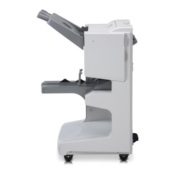
Page 29: 8-Bin Mailbox
8-bin mailbox Flipper Face-up bin Attachment rod Face-down bins Figure 13. External assembly locations—8-bin mailbox (left side view) Input paper guide Delivery head Power supply Belt Figure 14. External assembly locations—8-bin mailbox (right side view) ENWW Chapter 1 Product information 27... -
Page 30: Specifications
Specifications Multifunction finisher Table 1. Physical specifications—multifunction finisher Specification Multifunction finisher Measurements Height: 985 mm (38.8 inches) Width: 690 mm (27.2 inches) Depth: 60 mm (23.6 inches) Weight 44.4 kg (98 lb) Table 2. Electrical specifications—multifunction finisher Amperes Thermal units per hour Volts Frequency (amps) -
Page 31: 3,000-Sheet Stapler/Stacker
3,000-sheet stapler/stacker Table 5. Physical specifications—3,000-sheet stapler/stacker Specification HP 3,000-sheet stapler/stacker Measurements Height: 1,004 mm (39.5 inches) Width: 555 mm (21.8 inches) Depth: 536 mm (21.1 inches) Weight 32 kg (70.5 lb) Table 6. Electrical specifications—3,000-sheet stapler/stacker Amperes Thermal units per hour Volts Frequency (amps) -
Page 32: 3,000-Sheet Stacker
3,000-sheet stacker Table 9. Physical specifications—3,000-sheet stacker Specification HP 3,000-sheet stacker Measurements Height: 1,004 mm (39.5 inches) Width: 555 mm (21.8 inches) Depth: 536 mm (21.1 inches) Weight 32 kg (70.5 lb) Table 10. Electrical specifications—3,000-sheet stacker Amperes Thermal units per hour Volts Frequency (amps) -
Page 33: 8-Bin Mailbox
8-bin mailbox Table 13. Physical specifications—8-bin mailbox Specification 8-bin mailbox Measurements Height: 970 mm (38.2 inches) Width: 435 mm (17.1 inches) Depth: 480 mm (18.9 inches) Weight 19.2 kg (51.4 lb) Table 14. Power requirements and circuit capacity—8-bin mailbox Requirement or 110-volt models 220-volt models capacity... -
Page 34: Regulatory Information
The product herewith complies with the requirements of the EMC Directive 89/336/EEC and the Low Voltage Directive 73/23/EEC, and carries the CE-marking accordingly. The product was tested in a typical configuration with Hewlett-Packard Personal Computer Systems. This Device complies with Part 15 of the FCC Rules. Operation is subject to the following two... -
Page 35: Declaration Of Conformity-3,000-Sheet Stapler/Stacker
The product herewith complies with the requirements of the EMC Directive 89/336/EEC and the Low Voltage Directive 73/23/EEC, and carries the CE-marking accordingly. The product was tested in a typical configuration with Hewlett-Packard Personal Computer Systems. This Device complies with Part 15 of the FCC Rules. Operation is subject to the following two... -
Page 36: Declaration Of Conformity-3,000-Sheet Stacker
The product herewith complies with the requirements of the EMC Directive 89/336/EEC and the Low Voltage Directive 73/23/EEC, and carries the CE-marking accordingly. The product was tested in a typical configuration with Hewlett-Packard Personal Computer Systems. This Device complies with Part 15 of the FCC Rules. Operation is subject to the following two... -
Page 37: Declaration Of Conformity-8-Bin Mailbox
Voltage Directive 73/23/EEC, and carries the CE-Marking accordingly. 1) The product was tested in a typical configuration with Hewlett-Packard Personal Computer Systems. 2) This Device complies with Part 15 of the FCC Rules. Operation is subject to the following two... -
Page 38: Service Approach
Replacement parts can be ordered from the HP Customer Support (HPCS) organization. Exchange program Hewlett-Packard might offer remanufactured assemblies for parts. These can be ordered through HPCS. Warranty For warranty information and requirements, see the user guide for the printer. -
Page 39: Installation
Installation Chapter contents Environmental requirements ..........38 Physical requirements . -
Page 40: Environmental Requirements
Environmental requirements The electrical and environmental specifications must be maintained to ensure the correct operation of the output device. Consider the following points before installing the output device: Install in a well-ventilated, dust-free area. Install on a level, flat surface that can support the printer and output device size and weight. Ensure adequate power-supply circuitry (see table 2 on page 28). -
Page 41: Physical Requirements
Physical requirements Multifunction finisher Prepare a location for the output device. The space must accommodate the physical and environmental requirements contained in this section, in addition to the requirements for the printer. 690 mm 520 mm (27.2 inches) (20.5 inches) Figure 15. -
Page 42: 3,000-Sheet Stapler/Stacker And 3,000-Sheet Stacker
3,000-sheet stapler/stacker and 3,000-sheet stacker Note Dimensions of the 3,000-sheet stapler/stacker and the 3,000-sheet stacker are identical. 555 mm 520 mm 21.8 inches (20.5 inches) Figure 16. 3,000-sheet stapler/stacker (side view and top view) 40 Installation ENWW... -
Page 43: 8-Bin Mailbox
8-bin mailbox 480 mm (18.9 in) 435 mm 630 mm (17.1 in) (24.8 in) 918 mm 970 mm (36.1 in) (38.2 in) Figure 17. 8-bin mailbox (top view and side view) ENWW Chapter 2 Installation 41... - Page 44 42 Installation ENWW...
-
Page 45: Operation
Operation Chapter contents Supported media ........... . . 44 Multifunction finisher . -
Page 46: Supported Media
Supported media Multifunction finisher Output bin Capacity Media Feeding Weight orientation¹ Stacker bin (bin 1) Up to 1,000 sheets of 75 g/m (20 lb) Letter, ISO A4 P or L 64 to 216 g/m capacity, face-up bond, stacked, of letter/A4 (17 to 58 lb) Legal, ledger, Up to 500 sheets of 75 g/m... - Page 47 Output bin Capacity Media Feeding Weight orientation¹ Booklet bin (bin 2) Up to 40 booklets composed of 5 sheets Letter, legal, ledger, 64 to 199 g/m capacity (see “Number of sheets that can be ISO A4, ISO A3, JIS B4 (17 to 53 lb) stapled and folded, listed by booklet size”...
-
Page 48: 3,000-Sheet Stapler/Stacker
3,000-sheet stapler/stacker Function Capacity Media Weight Bin 1 (face-up Up to 125 sheets of letter/ Letter, legal, executive, ISO A3, 64 to 216 g/m (17 to bin) ISO A4, ISO A5, 11 x 17, JIS B5, 58 lb bond) JIS B4, JPostD, Monarch, 8K, Custom sizes Custom types: envelopes, labels, transparencies, heavy paper... -
Page 49: 8-Bin Mailbox
8-bin mailbox Output bin Capacity Media size Media Weight Face-down bins Up to 250 Standard sizes: plain 64 to 135 g/m sheets letter, legal, ISO A3, ISO A4, (17 to 36-lb bond) preprinted ISO A5, 11 x 17, JIS B4, JIS letterhead B5, 8k, 16k prepunched... -
Page 50: Using Media
Using media Multifunction finisher Table 17. Approximate number of sheets that can be stapled, listed by media weight Media weight Letter/A4 Ledger/A3 and legal/B4 64 g/m (17 lb) 75 g/m (20 lb) 80 g/m (21 lb) 90 g/m (24 lb) 105 g/m (28 lb) 163 g/m... -
Page 51: Table 20. Skew Specifications-Multifunction Finisher
Table 20. Skew specifications—multifunction finisher Skew type Specification Diagram Folding X = +/- 2.5 mm (0.10 inch), specified at center Y = +/- 2.5 mm (0.10 inch), length Feeding direction NOTE: The measurement is affected by expansion or shrinkage of the sheet as a result of fusing. -
Page 52: 3,000-Sheet Stapler/Stacker
3,000-sheet stapler/stacker Table 21. Approximate number of sheets that can be stapled, listed by media weight Media weight Letter/A4 Ledger/A3 and legal/B4 64 g/m (17 lb) 75 g/m (20 lb) 80 g/m (21 lb) 90 g/m (24 lb) 105 g/m (28 lb) 163 g/m (43 lb) -
Page 53: Maintenance
Maintenance Chapter contents Cleaning the outside of the product ........52 Cleaning inside the product . -
Page 54: Cleaning The Outside Of The Product
Cleaning the outside of the product When outside covers and panels are noticeably dirty, wipe them with a dampened cloth. Cleaning inside the product Over time, dust can accumulate inside the output device. Removing the dust is not a requirement for smooth operation of the products. -
Page 55: Theory Of Operation
Theory of operation Chapter contents Power-on sequence ........... 54 Multifunction finisher . -
Page 56: Power-On Sequence
Power-on sequence Multifunction finisher The multifunction finisher performs an initialization procedure when it receives the Recovery Initialize signal. This signal is transmitted from the printer at power-on. The power-on sequence consists of the following actions: Moves slide: The booklet bin slide motor (M10) drives the slide to move from the standby position. -
Page 57: 8-Bin Mailbox
8-bin mailbox When the 8-bin mailbox is turned on, the flipper and eject assemblies receive the initialization command and start the rollers in an attempt to eject any paper in the path. Then the assemblies check the sensors. If the sensors detect media, they signal an initial jam. If no jam exists, initialization for the flipper and eject assemblies is complete. -
Page 58: Basic Operation
Basic operation Multifunction finisher The multifunction finisher ejects paper from the printer either face-down or face-up. Operations such as job offset are performed when paper is ejected face-down. The booklet unit inside the multifunction finisher folds the paper stack before ejecting it. The controller PCA in the multifunction finisher controls the sequence of operations. -
Page 59: Figure 19. Simple Stacking (Face-Down Delivery)
Simple stacking Flipping action (face-down delivery): After the paper is reversed, the paper is pulled into the processing tray and ejected face- down to the delivery tray. Figure 19. Simple stacking (face-down delivery) Face-up delivery: The paper is pulled into the processing tray and ejected face-up to the delivery tray. Figure 20. -
Page 60: Offset Specifications
Job offset Job offset is accomplished by moving sheet by sheet forward or backward for sorting while transporting it to the stacker bin. The offset motor is connected to a crank system that moves offset carriage to the left and to the right. The offset position sensor detects the position of the offset module to position it left, right, or center. -
Page 61: Figure 22. Staple Positions
Stapling The multifunction finisher staples the specified number of sheets of paper. The staple position depends on the staple mode and paper size. Paper width Paper width X 1/2 Side stitching—two staples 120 Landscape-image mm (4.72 inches) apart stapling (front) Paper width Paper width X 1/2... -
Page 62: Figure 24. Booklet Making (1 Of 3)
Booklet-making Paper-fold rollers and the paper-pushing plate fold paper in the multifunction finisher. When the rollers start to rotate, the paper-pushing plate pushes the paper stack into the gap between the paper-fold rollers. When the paper stack is fed approximately 10 mm (0.4 inch) by the rotation of the paper-fold rollers, the paper-pushing plate returns to the home position. -
Page 63: Figure 26. Booklet Making (3 Of 3)
Paper stack Inlet Paper-pushing plate Outlet Paper stack Folds/feeds a paper stack Feeds a paper stack Figure 26. Booklet making (3 of 3) ENWW Chapter 5 Theory of operation 61... -
Page 64: 3,000-Sheet Stapler/Stacker
3,000-sheet stapler/stacker Main modules The 3,000-sheet stapler/stacker consists of the following main modules: Face-up bin—This bin collects the documents face-up, with the printed information toward the user. Finished documents are not routed to this bin, but the bin supports the sheets as they are flipped to the face-down bin. -
Page 65: Figure 28. Stapler/Stacker Jam Detection
Paper path and jam detection Paper input—The device receives media from the printer. Flipper—FLEntry1 senses the media and activates the flipper motors. For face-up printing, the flipper delivers the media (which the FLEntry senses) to the face-up bin. Otherwise, the flipper changes page orientation from face-up to face-down and delivers media to the paper- path module. -
Page 66: Figure 29. Stapler-Bin-Full Condition
Stapler/stacker bin full condition The stapler bin signals a “full” condition when either of these conditions exist: Approximately 3,000 sheets of letter/A4 have been collected in the stapler bin Approximately 1,500 sheets of ledger/A3 have been collected in the stapler bin Note A full-bin condition is signaled when the stapler bin contains 15 kg (33 lb) of paper. -
Page 67: Offset Specifications
Offset specifications Table 23. Offset specifications for the 3,000-sheet stapler/stacker Offset specification for Offset specification Distance per side Distance per side for Letter for A4 for Letter Up to 15 mm (0.59 inches) Up to 6 mm (0.24 inches) Up to 7.5 mm Up to 3 mm (0.12 inches) (0.30 inches) ENWW... -
Page 68: 3,000-Sheet Stacker
3,000-sheet stacker Main modules The stacker consists of the following main modules: Face-up bin—This bin collects the documents face-up, with the printed information toward the user. Finished documents are not routed to this bin, but the bin supports sheets as they are flipped to the face-down bin. -
Page 69: Figure 31. Stacker Jam Detection
Paper path and jam detection Paper input—The device receives media from the printer. Flipper—FLEntry1 senses the media and activates the flipper motors. For face-up printing, the flipper delivers the media to the face-up bin. Otherwise, the flipper changes page orientation from face-up to face-down and delivers the media to the paper-path module. Paper path—The paper-path module delivers face-down print jobs to the offset module. -
Page 70: Offset Specifications
Stacker-bin-full condition The stapler bin signals a “full” condition when either of these conditions exist: Approximately 3,000 sheets of letter/A4 have been collected in the stapler bin Approximately 1,500 sheets of ledger/A3 have been collected in the stapler bin Note A full-bin condition is signaled when the stapler bin contains 15 kg (33 lb) of paper. -
Page 71: 8-Bin Mailbox
8-bin mailbox Main modules The 8-bin mailbox has 9 bins for sorting and handling printed media. The topmost bin receives the media face-up as it comes from the printer. The remaining eight bins receive the media face- down. The destination bin for the printed media depends on the device operating mode and the presence of media. -
Page 72: Figure 33. 8-Bin Mailbox Main Modules
Flipper Face-up bin Attachment rod Face-down bins Input paper guide Delivery head Power supply Belt Figure 33. 8-bin mailbox main modules 70 Theory of operation ENWW... -
Page 73: Figure 34. 8-Bin Mailbox Paper Path
Paper-path and jam detection Flipper—The flipper assembly receives the media from the printer or MFP. When it receives a delivery notice from printer or MFP, the flipper motor starts to move at the print or copy speed. When the ENTRY sensor is activated, the sheet is measured. If the sheet goes to the face-up bin, the FACEUP sensor is deactivated to signal the end of the paper-handling function and the sheet is ejected immediately. - Page 74 Bin-full condition Mailbox mode—The capacity status of each logical face-down bin depends on how the sensor behaves in the face-down bin. A bin-full condition results from either of the following events: • The bin-full sensor is activated when media is delivered to a face-down bin. •...
-
Page 75: Electric Circuitry
Electric circuitry A 16-bit microprocessor is installed on the finisher controller PCB to control the finisher operation sequence and the Jet-Link communication with the video controller PCB. The finisher controller PCB drives solenoids and motors in response to the commands that the video controller PCB sends through the Jet-Link communication line. -
Page 76: Power Supply
Power supply Multifunction finisher The multifunction finisher power supply adopts a remote switching system. At power on, the printer issues a command to the video controller PCB. The video controller PCB then sends a power-on signal (PWRON-IN signal) to the power supply. When the PWRON-IN signal is at the high (“H”) level, the power-supply circuit supplies +24 V power and +5 V power to the finisher controller PCB. -
Page 77: 8-Bin Mailbox
8-bin mailbox A universal power supply is activated when the MFP or printer power switch is turned on. The MFP or printer paper-handling controller sends a power-on signal to the power supply through the controller PCB. The power-supply circuit provides +24 V for motors and +5 V for sensors and controller electronics. -
Page 78: Motors, Solenoids, And Clutches
Motors, solenoids, and clutches Multifunction finisher Figure 37. Motors, solenoids, and clutches Table 25. Motors, solenoids, and clutches for feeding and aligning media Name Function Module Error Code zz Feed motor Rotates the feed and delivery rollers (R1 Whole unit and R2) in the paper-feed direction, and rotates R3 in the paper-folding direction Paddle motor... -
Page 79: 8-Bin Mailbox
Table 25. Motors, solenoids, and clutches for feeding and aligning media Name Function Module Error Code zz Fan motor Provides air flow to the stacker bin to Whole unit improve stacking quality Flapper solenoid Switches the flapper up and down to Flipper assembly 21, 22, redirect media to either the face-up or... -
Page 80: Sensors
Sensors Multifunction finisher PI15 PI16 PI17 PI23 PI13 PI22 Figure 39. Sensors—multifunction finisher (1 of 5) Number Description Function Location Aligning plate home-position Detects the aligning plate (front) at the Whole unit sensor (front) home position PI13 Booklet bin-full sensor Detects the paper-full condition in the Whole unit booklet bin... -
Page 81: Figure 40. Sensors-Multifunction Finisher (2 Of 5)
PI14 Figure 40. Sensors—multifunction finisher (2 of 5) Number Description Function Location Paddle home-position sensor Detects the paddle at the home position Whole unit Swing guide home-position sensor Detects the swing guide at the home Whole unit position Aligning plate home-position Detects the aligning plate (back) at the Whole unit sensor (back) -
Page 82: Figure 41. Sensors-Multifunction Finisher (3 Of 5)
PI12 PI10 PI11 PI32 Figure 41. Sensors—multifunction finisher (3 of 5) Number Description Function Location Feed-path sensor Detects the media in the feed path Whole unit PI10 Folding-position sensor Detects the paper in the folding position Folding mechanism PI11 Folding home-position sensor Detects the fold roller and the pushing Folding plate at the home position... -
Page 83: Figure 42. Sensors-Multifunction Finisher (4 Of 5)
PI19 PI24 PI20 PI21 PI18 Figure 42. Sensors—multifunction finisher (4 of 5) Number Description Function Location PI18 Slide home-position sensor Detects the staple unit at the home Stapler position assembly PI19 Stapler home-position sensor Detects the stapling operation at the Stapler home position assembly... -
Page 84: Figure 43. Sensors-Multifunction Finisher (5 Of 5)
PI25 PI31 PI28 PI26-1 PI26-2 PI27 PI30 PI29 Figure 43. Sensors—multifunction finisher (5 of 5) Number Description Function Location PI25 Stapler full-stack sensor Detects that the delivery tray is full Whole unit PI26-1 Reversal sensor (emitter) Detects the paper at the reverse unit Flipper assembly PI26-2... -
Page 85: 3,000-Sheet Stapler/Stacker
3,000-sheet stapler/stacker FLENTRY FLFUF FLENTRY1 FLEXIT ACGWHL ACENTRY ACEXIT PPEXIT ACRTAIN Figure 44. Sensors—3,000-sheet stapler/stacker Name Description Function Location FLFUF Flipper face-up bin full Detects the bin-full condition in Flipper the face-up bin FLENTRY1 Flipper paper arrival Detects when media arrives to Flipper sensor the output device... -
Page 86: 3,000-Sheet Stacker
3,000-sheet stacker FLENTRY FLFUF FLENTRY1 FLEXIT OMOFFSET OMEXIT PPEXIT Figure 45. Sensors—3,000-sheet stacker Name Description Function Location FLFUF Flipper face-up bin full Detects the bin-full condition in Flipper the face-up bin FLENTRY1 Flipper paper arrival Detects when media arrives at Flipper sensor the output device... -
Page 87: 8-Bin Mailbox
8-bin mailbox FACE_UP_FULL FACE_UP ENTRY EXIT1 SLIDER HEAD_POS PAPER_PRESENCE EXIT2 Figure 46. Sensors—8-bin mailbox Name Description Function Location FACE_UP_FULL Left-output-bin-full sensor Detects a bin-full condition in the Face-up bin face-up bin ENTRY Paper-entry sensor Detects media that is entering Flipper the 8-bin mailbox and triggers the start of the flipper motor to transport media into the 8-bin... - Page 88 Name Description Function Location EXIT2 Paper-delivered-to-bin Indicates that a sheet of media Head assembly sensor has exited to a face-down bin, and turns off the eject motor FACE_UP Reverse-stepper-motor Detects media that is completely Flipper sensor ejected to the face-up bin, or media that has been flipped and is toward the belt 86 Theory of operation...
-
Page 89: Removal And Replacement
Removal and replacement Chapter contents Introduction ............89 Removal and replacement strategy . - Page 90 Stationary caster (front right) ........128 3,000-sheet stapler/stacker and 3,000-sheet stacker external doors and covers.
-
Page 91: Introduction
Introduction Removal and replacement strategy This chapter documents the removal and replacement of field replaceable units (FRUs) only for the output devices. Replace parts in the reverse order of their removal. Directions for difficult or critical replacement procedures are included. WARNING! The sheet-metal edges of the output device can be sharp. -
Page 92: Before Performing Service
Before performing service Remove all media from the output device. Unplug the power cord and the Jet-Link cable (interface cable). Separate the output device from the printer. Place the output device on an ESD mat. If an ESD mat or an ESD-protected workstation is not available, discharge body static and ground the output device chassis before servicing the output device. -
Page 93: Multifunction Finisher External Doors And Covers
Multifunction finisher external doors and covers Stapler door Open the stapler door. Remove one small, self-tapping screw (callout 1) to release the strap. Remove the e-clip (callout 2) from the hinge. Slide the door upward to remove it from the pins. Figure 47. -
Page 94: Product-Release Handle
Product-release handle Open the stapler door. Use a flatblade screwdriver to lift and release the tab (callout 1). Lift the handle upward to release an internal tab (callout 2), and remove the product-release handle. Figure 48. Product-release handle (1 of 2) 92 Removal and replacement ENWW... -
Page 95: Figure 49. Product-Release Handle (2 Of 2)
Reinstall notes Complete these actions before reinstalling the product-release handle: Move the internal latching mechanism (callout 3) toward the left side of the multifunction finisher. Be sure to align the spring (callout 4) with the inside edge (callout 5) of the product-release handle. -
Page 96: Folding Knob
Folding knob Open the stapler door. Use needle-nose pliers to pinch and release two tabs (callout 1). Remove the knob. Figure 50. Folding knob 94 Removal and replacement ENWW... -
Page 97: Handle-Mounting Gear
Handle-mounting gear Remove the folding knob. See page 94. Remove the e-clip (callout 1). Gently slide the handle-mounting gear (callout 2) out of the multifunction finisher. Figure 51. Handle-mounting gear ENWW Chapter 6 Removal and replacement 95... -
Page 98: Front Cover
Front cover Remove the folding knob. See page 94. Remove three screws (callout 1) from inside the stapler door. Figure 52. Front cover (1 of 2) 96 Removal and replacement ENWW... -
Page 99: Figure 53. Front Cover (2 Of 2)
Remove six more screws (callout 2) from the front cover. Pull one tab (callout 3) downward to release it. Lift the lower section of the cover upward to release two internal tabs (callout 4), and remove the cover. Figure 53. Front cover (2 of 2) Reinstall note CAUTION... -
Page 100: Back Cover
Back cover Remove six screws (callout 1). Lift the lower section of the cover upward to release an internal tab (callout 2). Figure 54. Back cover (1 of 2) Lift the cover slightly, and then slide it toward the output bins to release an internal tab (callout 3). -
Page 101: Upper Panel Assembly (Top Door)
Upper panel assembly (top door) Remove one screw (callout 1). If the stacker bin (callout 2) blocks the screw, push the stacker bin downward. CAUTION Use light pressure to push the stacker bin down slowly. Quick or heavy pressure can break the bin. Slide the small plastic cover (callout 3) toward the stacker bin to remove it. -
Page 102: Internal-Path Cover (Dispose Subcover)
Internal-path cover (dispose subcover) Remove the following covers: • Front cover. See page 95. • Back cover. See page 98. • Upper panel assembly. See page 99. Remove one screw (callout 1). Unplug the cable connector (callout 2), and then remove the cable from the cable-retainer clip (callout 3). -
Page 103: Foot Cover
Foot cover Remove the following covers: • Front cover. See page 96. • Back cover. See page 98. Remove two screws (callout 1) from the right side of the multifunction finisher. Figure 60. Foot cover (1 of 2) Remove two screws (callout 2) from the left side of the multifunction finisher. Lift the foot cover upward to remove it. -
Page 104: Multifunction Finisher Assemblies
Multifunction finisher assemblies Paper-guide wire Face the right side of the multifunction finisher. Gently twist each pin to remove the wire. Figure 62. Paper-guide wire Reinstall note Make sure that each pin shoulder (callout 1) faces outward. 102 Removal and replacement ENWW... -
Page 105: Product-Attachment Latch
Product-attachment latch Locate the product-attachment latch at the end of the attachment-rod assembly. Remove one screw (callout 1) from the attachment-rod assembly. Slide the latch off of the rod. Figure 63. Product-attachment latch ENWW Chapter 6 Removal and replacement 103... -
Page 106: Stapling Unit
Stapling unit Open the stapler door. Pull the stapling unit out until it stops. Press the tab (callout 1) with a small flatblade screwdriver, and then resume sliding the stapling unit out of the multifunction finisher. Figure 64. Stapling unit 104 Removal and replacement ENWW... -
Page 107: Aligner Racks
Aligner racks Face the left side of the multifunction finisher. Locate the snap tabs (callout 1) on the outside of each aligner rack. Pinch each set of snap tabs with needle-nose pliers to release the aligner racks. Aligner racks Reinstall note The two aligner racks are not interchangeable. -
Page 108: Booklet Bin-Full Sensor Flag (Main Lever Weight Assembly)
Booklet bin-full sensor flag (main lever weight assembly) Face the left side of the multifunction finisher. Slide the booklet stopper (callout 1) away from the booklet bin-full sensor flag. Gently pull the two locating pins outward to release them. See the detail in figure 65. Remove the booklet bin-full sensor flag. -
Page 109: Paper Deflector (Deflector Weight)
Paper deflector (deflector weight) The paper deflector is in three parts. Callouts 1 and 3 in figure 66 show holders at one end of both the part at the back of the multifunction finisher and the part at the front. Callout 2 shows the holders at each end of the part at the center. -
Page 110: Figure 67. Paper Deflector (2 Of 2)
Reinstall notes The parts of the paper deflector that should be reinstalled toward the back and toward the front of the multifunction finisher contain mylar pieces that are shaped differently. Make sure that the part that contains the angled mylar piece is reinstalled at the back of the multifunction finisher, and that the part that contains the squared mylar piece is reinstalled at the front. -
Page 111: Anti-Static Brush
Anti-static brush Remove the following FRUs: • Front cover. See page 96. • Back cover. See page 98. • Upper panel assembly. See page 99. • Internal-path cover. See page 100. Remove one screw (callout 1). Slide the brush toward the front of the multifunction finisher to remove it. Figure 68. -
Page 112: Stacker Bin
Stacker bin Remove four screws (callout 1). Gently slide the stacker bin upward until the attachment hooks (callout 2) slide out of the metal slots on the multifunction finisher. Stacker bin (1 of 2) Reinstall note Align the two attachment hooks with the metal slots on the multifunction finisher. Align the stacker bin with the two locating pins (callout 3). -
Page 113: Booklet Bin
Booklet bin Remove the following FRUs: • Front cover. See page 101. • Paper-guide wire. See page 102. Hint To make parts-removal easier, remove the booklet bin-full sensor flag. See page 106. Face the right side of the multifunction finisher, and open the jam-removal cover. Remove two self-tapping screws (callout 1). -
Page 114: Figure 71. Booklet Bin (3 Of 4)
CAUTION Be careful when rotating the booklet bin to avoid damaging the cables. Gently rotate the booklet bin until you see two cable connectors (callout 4). Unplug the two cable connectors. Figure 71. Booklet bin (3 of 4) Reinstall notes Make sure that you reconnect the cable connectors before you install the booklet bin. -
Page 115: Stapling-Door Switch
Stapling-door switch Remove the front cover. See page 96. Unplug two cable connectors (callout 1), and unroute the cables from the cable guides (callout 2). Unplug the voltage connector (callout 3). Remove one screw (callout 4). Remove the stapling-door switch. Figure 73. -
Page 116: Interlock Switch
Interlock switch Remove the following FRUs: • Front cover. See page 96. • Back cover. See page 98. Remove four screws (callout 1), and then remove the flipper-assembly cover. Figure 74. Interlock switch (1 of 2) Remove one screw (callout 2). Unplug the voltage connector (callout 3). -
Page 117: Flipper Assembly
Flipper assembly Remove the following FRUs: • Front cover. See page 96. • Back cover. See page 98. • Paper-guide wire. See page 102. Remove four screws (callout 1). Unplug the interlock-switch voltage connector (callout 2). Figure 76. Flipper assembly (1 of 3) Unplug three cable connectors (callout 3). -
Page 118: Figure 78. Flipper Assembly (3 Of 3)
Reinstall note Align the flipper assembly with the guide pins (callout 4). Figure 78. Flipper assembly (3 of 3) 116 Removal and replacement ENWW... -
Page 119: Folding Mechanism
Folding mechanism Remove the following FRUs: • Front cover. See page 96. • Back cover. See page 98. • Stapling unit. See page 104. • Flipper assembly. See page 115. Face the back of the multifunction finisher. Unplug three cable connectors (callout 1). Remove the plastic e-clip (callout 2), and then remove the round plastic cover (callout 3) from the timing-belt gear. -
Page 120: Figure 81. Folding Mechanism (3 Of 6)
Face the back of the multifunction finisher. Remove the timing belt (callout 6) from the timing-belt gear. Note Removing the timing belt loosens the timing-belt gear. Do not drop or misplace this gear. Figure 81. Folding mechanism (3 of 6) 10 Face the front of the multifunction finisher. -
Page 121: Figure 83. Folding Mechanism (5 Of 6)
12 Hold the folding blade (callout 8) inside, so that the folding mechanism can clear the frame (callout 9). Figure 83. Folding mechanism (5 of 6) Reinstall note Install the timing belt (callout 10) underneath the tensor shaft (callout 11). Make sure that the timing-belt teeth are on the inside of the belt. -
Page 122: User Led Pca
User LED PCA Remove the front cover. See page 96. Remove one screw (callout 1) from the plastic holder. Unplug one cable connector (callout 2). Remove the user LED PCA by sliding it out of the plastic holder (callout 3). Figure 85. -
Page 123: Controller Pca
Controller PCA Remove the back cover. See page 98. Use a flatblade screwdriver to pry out the NVRAM chip (callout 1), and then set the NVRAM chip aside for installation into the new controller PCA. Figure 86. Controller PCA (1 of 3) Unplug 23 cable connectors (callout 2). -
Page 124: Figure 88. Controller Pca (3 Of 3)
Remove one screw (callout 3). Release three tabs (callout 4), and remove the PCA. Figure 88. Controller PCA (3 of 3) 122 Removal and replacement ENWW... -
Page 125: Service Led Pca
Service LED PCA Remove the back cover. See page 98. Remove one screw (callout 1). Unplug one cable connector (callout 2). Remove the service LED PCA from the multifunction finisher. Figure 89. Service LED PCA ENWW Chapter 6 Removal and replacement 123... -
Page 126: Power Supply
Power supply Remove the back cover. See page 98. Unplug one cable connector (callout 1). Remove three screws (callout 2). From the inner-facing side of the metal panel, remove one screw (callout 3). Figure 90. Power supply 124 Removal and replacement ENWW... -
Page 127: Jet-Link Cable (Interface Cable)
Jet-Link cable (interface cable) Remove the back cover. See page 98. Unplug one cable connector (callout 1) from the controller PCA. Open the five cable clips (callout 2), and unroute the cable (callout 3). Figure 91. Jet-Link cable (1 of 2) Remove one screw (callout 4). -
Page 128: Adjustable Casters (Left Side)
Adjustable casters (left side) Note For safety, first remove the stapling unit (see page 104), and then gently lay the multifunction finisher on its side. (Figure 93 shows the multifunction finisher in an upright position.) Front left caster Remove the front cover. See page 96. Remove the e-clip (figure 93, callout 1) from the metal pin. -
Page 129: Stationary Extended Caster (Back Right)
Stationary extended caster (back right) Note For safety, first remove the stapling unit (see page 104), and then gently lay the multifunction finisher on its side. (Figure 94 shows the multifunction finisher in an upright position.) Remove four screws (callout 1). Turn the caster to release a small metal hook (callout 2). -
Page 130: Stationary Caster (Front Right)
Stationary caster (front right) Note For safety, first remove the stapling unit (see page 104), and then gently lay the multifunction finisher on its side. (Figure 95 shows the multifunction finisher in an upright position.) Remove two screws (callout 1). Slide the caster out. -
Page 131: 3,000-Sheet Stapler/Stacker And 3,000-Sheet Stacker External Doors And Covers
3,000-sheet stapler/stacker and 3,000-sheet stacker external doors and covers Face-up bin Tilt the end of the face-up bin upward (figure 96, callout 1). Remove the face-up bin. Stapler/stacker bin (stapler/stacker only) or stacker bin (stacker only) Note Throughout this chapter, this bin is called the “stapler/stacker bin.” Unhook the plastic tabs under the bin (callout 2). -
Page 132: Back Inner Cover And Front Inner Cover
Back inner cover and front inner cover Remove the following bins: • Face-up bin. See page 129. • Stapler/stacker bin. See page 129. Use a Torx #20 screwdriver to remove six screws from the back inner cover (callout 1). Figure 97. Back inner cover and front inner cover Pull the back inner cover away from the back cover until it releases. -
Page 133: Front Cover
Front cover Remove the following FRUs: • Face-up bin. See page 129. • Stapler/stacker bin. See page 129. • Back inner cover. See page 130. • Front inner cover. See page 130. Use a Torx #20 screwdriver to remove three screws (callout 1). Figure 98. -
Page 134: Back Cover
Back cover Remove the following FRUs: • Face-up bin. See page 129. • Stapler/stacker bin. See page 129. • Back inner cover. See page 130. • Front inner cover. See page 130. Use a small flatblade screwdriver to release the bubbled (cable) cover. Remove the cable cover (callout 1). -
Page 135: Figure 100. Back Cover (2 Of 2)
Use a Torx #20 screwdriver to remove three screws (callout 2). Press and hold the interlock switch (callout 3) while lifting the cover upward until the cover releases from the output device. Figure 100. Back cover (2 of 2) Guide both cables out of the cavity. To reinstall CAUTION To prevent damage, make sure that the three locking tabs (not shown) are locked into the output... -
Page 136: Foot Cover
Foot cover Remove the following FRUs: • Face-up bin. See page 129. • Stapler/stacker bin. See page 129. • Back inner cover. See page 130. • Front inner cover. See page 130. • Front cover. See page 131. • Back cover. See page 132. Grasp the sides of the foot cover, and pull it out and up to clear the locating pin. -
Page 137: Controller Pca Cover
Controller PCA cover Use a Torx screwdriver to remove four screws (callout 1) from the cover. Figure 102. Controller PCA cover Rotate the cover to clear the tabs. Remove the controller PCA cover. To reinstall Make sure that you insert the power cord rubber grommet (callout 2) into the slot on the bottom of the cover. -
Page 138: Door Assembly
Door assembly Open the door assembly. Use a Torx #20 screwdriver to remove two screws (callout 1) from the plastic strips inside the door. Note The screws remain attached to the plastic strips. Figure 103. Door assembly Rotate the door downward until the flat sides of the hinges are parallel to the floor. Remove the door assembly. -
Page 139: 3,000-Sheet Stapler/Stacker And 3,000-Sheet Stacker Assemblies
3,000-sheet stapler/stacker and 3,000-sheet stacker assemblies Flipper assembly Remove the following FRUs: • Face-up bin. See page 129. • Stapler/stacker bin. See page 129. • Back inner cover. See page 130. • Front inner cover. See page 130. • Front cover. See page 131. •... -
Page 140: Paper-Path Assembly
Paper-path assembly Remove the following FRUs: • Face-up bin. See page 129. • Stapler/stacker bin. See page 129. • Back inner cover. See page 130. • Front inner cover. See page 130. • Front cover. See page 131. • Back cover. See page 132. Unplug the paper-path ribbon cable (callout 1) by pressing the black tabs on the cable connector. -
Page 141: Accumulator Wings (Stapler/Stacker Only)
Accumulator wings (stapler/stacker only) Grasp each accumulator wing near the shaft. Slide the wings toward the center of the shaft. Apply slight downward pressure to disengage the wings. Press the locking tabs (callout 1) on the rotation pins, and push the pins out of the mounting holes. -
Page 142: Paper-Stop Clips
Paper-stop clips Use a small flatblade screwdriver to spread the paper-stop clips (callout 1) and to disengage the tabs. Figure 107. Paper-stop clips Grasp the paper-stop clips and gently pull them away from the output device to disengage the shaft. Note Paper-stop clips must be installed correctly in order to prevent paper from dropping or jamming. -
Page 143: Accumulator Assembly (Stapler/Stacker Only)
Accumulator assembly (stapler/stacker only) Remove the following FRUs: • Face-up bin. See page 129. • Stapler/stacker bin. See page 129. • Back inner cover. See page 130. • Front inner cover. See page 130. • Front cover. See page 131. •... -
Page 144: Figure 109. Accumulator Assembly (2 Of 3)
Unlatch the ribbon retention wire (callout 2). Note Do not remove the wire from the product when you unlatch it. Figure 109. Accumulator assembly (2 of 3) 142 Removal and replacement ENWW... -
Page 145: Figure 110. Accumulator Assembly (3 Of 3)
Use a Torx #20 screwdriver to remove four mount screws (callout 3). Figure 110. Accumulator assembly (3 of 3) Note Make sure that you remove the accumulator wings and the paper-stop clips before proceeding to step 6. Grasp the accumulator assembly on each side and lift up to clear the tabs. Remove the accumulator assembly. -
Page 146: Carriage Assembly (Stapler/Stacker Only)
Carriage assembly (stapler/stacker only) Remove the following FRUs: • Face-up bin. See page 129. • Stapler/stacker bin. See page 129. • Back inner cover. See page 130. • Front inner cover. See page 130. • Front cover. See page 131. •... -
Page 147: Figure 112. Carriage Assembly (2 Of 2)
Use a Torx #20 screwdriver to remove two mount screws (callout 2). Figure 112. Carriage assembly (2 of 2) Grasp the carriage assembly on each side and lift up to clear the tabs. Remove the carriage assembly. ENWW Chapter 6 Removal and replacement 145... -
Page 148: Offset Module (Stacker Only)
Offset module (stacker only) Remove the following FRUs: • Face-up bin. See page 129. • Stapler/stacker bin. See page 129. • Back inner cover. See page 130. • Front inner cover. See page 130. • Front cover. See page 131. •... -
Page 149: Figure 114. Offset Module (2 Of 2)
Use a Torx #20 screwdriver to remove four mount screws (two shown, callout 2). Figure 114. Offset module (2 of 2) Grasp the offset module on each side and lift up to clear the tabs. Remove the offset module. ENWW Chapter 6 Removal and replacement 147... -
Page 150: Stapler (Stapler/Stacker Only)
Stapler (stapler/stacker only) Remove the following FRUs: • Face-up bin. See page 129. • Stapler/stacker bin. See page 129. • Back inner cover. See page 130. • Front inner cover. See page 130. • Front cover. See page 131. • Back cover. See page 132. •... -
Page 151: Figure 116. Stapler (2 Of 2)
Lift the stapler up and disconnect the cables (callout 2) from the connectors (callout 3). Figure 116. Stapler (2 of 2) ENWW Chapter 6 Removal and replacement 149... -
Page 152: Controller Pca
Controller PCA Note See figure 117 for the stapler/stacker or figure 118 for the stacker. Remove the following FRUs: • Face-up bin. See page 129. • Stapler/stacker bin. See page 129. • Back inner cover. See page 130. • Back cover. See page 132. •... -
Page 153: Figure 118. Stacker Controller Pca
Figure 118. Stacker controller PCA ENWW Chapter 6 Removal and replacement 151... -
Page 154: Power Supply
Power supply Note See figure 119 for the stapler/stacker or figure 120 for the stacker. Remove the controller PCA cover. See page 135. Unplug the power cable (callout 1) from the power supply. Unplug the cable from the controller PCA (callout 2). Stapler/stacker: Use a Torx #20 screwdriver to remove eight screws (figure 119;... -
Page 155: Led Pca
LED PCA Remove the following FRUs: • Face-up bin. See page 129. • Stapler/stacker bin. See page 129. • Front inner cover. See page 130. • Front cover. See page 131. Unplug one cable (callout 1) from the LED PCA. Push the release tab (callout 2) and lift out the LED PCA. -
Page 156: Interlock Switch
Interlock switch Remove the following FRUs: • Face-up bin. See page 129. • Stapler/stacker bin. See page 129. • Back inner cover. See page 130. • Back cover. See page 132. Unplug two cable connectors (callout 1) from the interlock switch. Squeeze the top and the bottom of the interlock switch (callout 2), and push the switch through the hole. -
Page 157: Safety-Switch Assembly (Stapler/Stacker Only)
Safety-switch assembly (stapler/stacker only) Press the two tabs on the sides of the safety-switch assembly cover (callout 1) to release it from the frame. Lift the cover away from the safety-switch assembly. Disconnect two cables (callout 2) from the safety-switch assembly. Press the tabs on the bottom of the safety-switch assembly, and lift the safety-switch assembly away from the 3,000-sheet stapler/stacker. -
Page 158: Optical Sensors
Optical sensors Remove the following FRUs: • Face-up bin. See page 129. • Stapler/stacker bin. See page 129. • Back inner cover. See page 130. • Front inner cover. See page 130. • Front cover. See page 131. • Back cover. See page 132. •... -
Page 159: Figure 125. Optical Sensors (2 Of 3)
Remove two plastic ribs (callout 2). Figure 125. Optical sensors (2 of 3) Disconnect the cable from the optical sensor (callout 3). Press the optical-sensor-lock tab (callout 4) until it clears the output-device frame. Pull the sensor out and away from the output device. Note The sensor is secured with an adhesive strip. -
Page 160: Cable Assembly
Cable assembly Remove the following FRUs: • Face-up bin. See page 129. • Stapler/stacker bin. See page 129. • Back inner cover. See page 130. • Back cover. See page 132. • Controller PCA cover. See page 135. Disconnect the ribbon cables from the flipper assembly, the path assembly, and the controller PCA. -
Page 161: Casters
Casters Stationary caster Lay the output device on its front or back side, so that the caster being replaced is off of the floor. Use a Torx #20 screwdriver to remove one screw (callout 1) from the inside of the frame. Rotate the caster 90°... -
Page 162: 8-Bin Mailbox External Doors And Covers
8-bin mailbox external doors and covers Bubbled cover Use a small, flatblade screwdriver to remove the bubbled (cable) cover (callout 1). Figure 130. Bubbled cover 160 Removal and replacement ENWW... -
Page 163: Front Cover
Front cover WARNING! Unplug the power cord that connects the output device to the printer or MFP. Remove the 8-bin mailbox from the printer. Use a small, flatblade screwdriver to release the three retaining tabs. Figure 131. Front cover Rotate the front cover outward to remove the front cover. ENWW Chapter 6 Removal and replacement 161... -
Page 164: Back Cover
Back cover WARNING! Unplug the power cord that connects the output device to the printer or MFP. Remove the 8-bin mailbox from the printer. Remove the bubbled cover. See page 160. Remove one (middle) screw (callout 1). Note Do not remove the screws that have the painted heads (upper and lower screws). Figure 132. -
Page 165: Figure 134. Back Cover (3 Of 3)
Use a small, flatblade screwdriver to release the three retaining tabs. Figure 134. Back cover (3 of 3) Remove the back cover. ENWW Chapter 6 Removal and replacement 163... -
Page 166: Top Cover
Top cover Remove the following FRUs: • Front cover. See page 161. • Back cover. See page 162. On the front of the 8-bin mailbox, remove the single screw (callout 1) that is closest to the upper-right side of the 8-bin mailbox. Figure 135. -
Page 167: Figure 137. Top Cover (3 Of 3)
Lift the right side of the top cover. Figure 137. Top cover (3 of 3) ENWW Chapter 6 Removal and replacement 165... -
Page 168: Cable Channel
Cable channel Disconnect the controller PCA cable. Use a flatblade screwdriver and pinch the indicated side of the cable channel to remove it (callout 1). Figure 138. Cable channel 166 Removal and replacement ENWW... -
Page 169: Paper Bins And Blind Cover
Paper bins and blind cover Note The procedure for removing the paper bins and the blind cover is the same. Each bin rests in its labeled slot. Remove the face-up bin by lifting up the outer edge of the bin to clear the retaining notch. Remove the blind cover by pulling back, holding it by the lower edge, and then gently rotating the blind cover toward the front of the 8-bin mailbox to clear the retaining notch. - Page 170 To reinstall Make sure that the bins are securely seated in the retaining notch. Each bin might have a personalized label that assigns it to a specific user or group of users. Reinstall each bin in its appropriate location. 168 Removal and replacement ENWW...
-
Page 171: 8-Bin Mailbox Assemblies
8-bin mailbox assemblies Power supply Remove the 8-bin mailbox from the printer. Disconnect the power cable from the PCA. See figure 133. Remove the cable channel. See page 166. Disconnect the power cable at the top of the power supply. Remove the power supply by pressing the plastic retaining tabs (callout 1) that are on each side of the power supply. -
Page 172: Flipper Assembly
Flipper assembly Remove the following FRUs: • Front cover. See page 161. • Back cover. See page 162. • Top cover. See page 164. • Face-up bin and blind cover. See page 167. Remove one screw (callout 1) from the back of the 8-bin mailbox. Figure 142. -
Page 173: Figure 144. Flipper Assembly (3 Of 7)
On the left side of the 8-bin mailbox, hold down the jam-access handle (callout 3) while unplugging the ground wire (callout 4) that connects the input paper guide to the flipper motor. Note You can use needle-nose pliers or your fingers to unplug the ground wire. Figure 144. -
Page 174: Figure 146. Flipper Assembly (5 Of 7)
Using needle-nose pliers, remove one ground wire (callout 6). Figure 146. Flipper assembly (5 of 7) Using a flatblade screwdriver, release one plastic retaining tab (callout 7). Figure 147. Flipper assembly (6 of 7) 172 Removal and replacement ENWW... -
Page 175: Figure 148. Flipper Assembly (7 Of 7)
Hold the jam-access handle with one hand, pull the right side of the flipper assembly toward you with the other hand, and then pull the flipper assembly down to remove it. Figure 148. Flipper assembly (7 of 7) ENWW Chapter 6 Removal and replacement 173... -
Page 176: Delivery Head Motor
Delivery head motor Remove the back cover. See page 162. On the back of the 8-bin mailbox, disconnect one cable connector (callout 1). Figure 149. Delivery head motor (1 of 2) Remove two screws (callout 2). Figure 150. Delivery head motor (2 of 2) Remove the delivery head motor. -
Page 177: Transport Belt Motor
Transport belt motor Remove the back cover. See page 162. Release the controller PCA from the bottom of the 8-bin mailbox. See page 183. Disconnect one cable connector (callout 1). Figure 151. Transport belt motor (1 of 3) Remove two screws (callout 2). Figure 152. -
Page 178: Figure 153. Transport Belt Motor (3 Of 3)
Using needle-nose pliers, disconnect one cable connector (callout 3) from the encoder sensor. Figure 153. Transport belt motor (3 of 3) Gently remove the transport belt motor by releasing the small, plastic belt on the opposite side. To reinstall Make sure that you correctly reinstall the plastic belt to the gear on the opposite side of the motor before screwing the motor to the frame. -
Page 179: Input Paper Guide
Input paper guide Remove the 8-bin mailbox from the printer. Remove the face-up bin and the blind cover. See page 167. On the left side of the 8-bin mailbox, hold down the jam access handle (callout 1) while unplugging the ground wire (callout 2) that connects the input paper guide to the flipper motor. -
Page 180: Face-Up Full Lever
Face-up full lever Remove the face-up bin and blind cover. See page 167. Hold the face-up full lever (callout 1) and gently pull it toward you to remove it. Figure 156. Face-up full lever To reinstall Make sure that the plastic pin on the left side of the face-up full lever is correctly inserted into the square window. -
Page 181: Rollers Kit
Rollers kit Remove the face-up bin and blind cover. See page 167. Pull down the jam-access handle and remove each of the rollers by gently pulling it toward you. Figure 157. Rollers kit ENWW Chapter 6 Removal and replacement 179... -
Page 182: Magnets Assembly
Magnets assembly Remove the 8-bin mailbox from the printer or MFP. Unscrew the two magnet assemblies (callout 1) and remove the magnet assemblies from the printer or MFP. Figure 158. Magnets assembly 180 Removal and replacement ENWW... -
Page 183: Metal Tape And Housing Assembly
Metal tape and housing assembly Remove the following FRUs: • Output bin. See page 167. • Blind cover. See page 167. • Paper bins. See page 167. WARNING! The metal tape has sharp edges. Hold the metal tape toward the end and use a flatblade screwdriver to push and release the retainer tab (callout 1) that secures the end of the tape. -
Page 184: Figure 160. Metal Tape And Housing Assembly (2 Of 2)
Using a flatblade screwdriver, release two plastic retaining tabs (callout 3). Figure 160. Metal tape and housing assembly (2 of 2) Gently pull the delivery head assembly toward you to remove the end of the tape from behind the rollers that hold the tape in its track. Pull the tape housing toward you to remove it. -
Page 185: Controller Pca
Controller PCA Disconnect the power supply cable (callout 1) and the Jet-Link cable (callout 2). Figure 161. Controller PCA (1 of 4) Carefully lay the 8-bin mailbox on its front side (user LED side). Remove one grounding screw (callout 3) and loosen one screw (callout 4). Figure 162. -
Page 186: Figure 163. Controller Pca (3 Of 4)
Remove three self-tapping screws (callout 5). Figure 163. Controller PCA (3 of 4) Open the metal box. Disconnect the eight cable connectors (callout 6) and one ribbon cable (callout 7). Figure 164. Controller PCA (4 of 4) 184 Removal and replacement ENWW... -
Page 187: Anticurl Strings
Anticurl strings Remove the back cover. See page 162. Remove the following FRUs: • Output bin. See page 167. • Blind cover. See page 167. • Paper bins. See page 167. Remove two screws (callout 1). Remove the lower pulleys by pulling them toward you to release the anticurl strings (callout 2). - Page 188 Using a flatblade screwdriver, press the retaining tabs to remove the anticurl strings from the flipper. To reinstall Make sure that you put the anticurl string at the delivery head assembly before you reinstall the springs and the lower pulleys. Put the anticurl strings at the top of the flipper assembly after reinstalling the springs and lower pulleys.
-
Page 189: Delivery Head Assembly
Delivery head assembly Remove the output bin, the blind cover, and all of the paper bins. See page 167. WARNING! The metal tape has sharp edges. Note When rewinding the metal tape into its housing, hold the tape securely and rewind it slowly. With the delivery head assembly toward the top of the 8-bin mailbox, hold the metal tape near the end and use a flatblade screwdriver to push and release the retainer tab (callout 1) that secures the end of the tape. -
Page 190: Figure 169. Delivery Head Assembly (3 Of 6)
On the back of the 8-bin mailbox, release the flat ribbon cable (callout 4) from the cable clip and gently disconnect the flat ribbon cable from the delivery head assembly. Figure 169. Delivery head assembly (3 of 6) Lift the delivery head assembly to the top of the 8-bin mailbox and remove two screws (callout 5). -
Page 191: Figure 171. Delivery Head Assembly (5 Of 6)
Rotate the delivery head assembly clockwise while guiding the back of the delivery head assembly out of its access opening. Figure 171. Delivery head assembly (5 of 6) Release the anticurl strings from the pulleys (callout 6) on each end of the delivery head assembly by pulling out the pulley’s lock. -
Page 192: Interlock Switch
Interlock switch Remove the back cover. See page 162. CAUTION Before removing the wires from the interlock switch, note the location of each wire. Replacing the wires incorrectly can damage the interlock switch. Disconnect two wires (callout 1) and then press two retaining tabs (callout 2). Figure 173. -
Page 193: Diagnostic Led Pca
Diagnostic LED PCA Remove the back cover. See page 162. Disconnect two flat cable connectors (callout 1) and remove one screw (callout 2). Figure 174. Diagnostic LED PCA Remove the diagnostic LED PCA. ENWW Chapter 6 Removal and replacement 191... -
Page 194: User Status Led Pca
User status LED PCA Remove the front cover. See page 161. Disconnect one cable connector (callout 1) and remove one screw (callout 2). Figure 175. User status LED PCA Remove the user status LED PCA. 192 Removal and replacement ENWW... -
Page 195: Adjustable, Fixed, And Extended Fixed Casters
Adjustable, fixed, and extended fixed casters Note The procedure for removing all of the casters is the same. Carefully lay the 8-bin mailbox on its front side. Select the caster that you want to remove and then remove two screws (callout 1). Figure 176. -
Page 196: Attachment Assembly
Attachment assembly Carefully lay the 8-bin mailbox on its front side. Using needle-nose pliers, remove the e-clip (callout 1) and release the pivot pin (callout 2). Remove one screw to release the grounding wire (callout 3). Figure 177. Attachment assembly Remove the attachment assembly. -
Page 197: Troubleshooting
Troubleshooting Chapter contents Understanding the troubleshooting process....... . 196 Preliminary operating checks ........197 Troubleshooting flowchart . -
Page 198: Understanding The Troubleshooting Process
Understanding the troubleshooting process The troubleshooting process is a systematic approach that addresses the primary problems first, and then other problems, to discover the causes for output device malfunctions and errors. The troubleshooting flowchart on page 198 illustrates the primary steps for troubleshooting. An answer to a troubleshooting question allows troubleshooting to proceed to the next primary step. -
Page 199: Preliminary Operating Checks
Preliminary operating checks Make sure that the conditions in the following lists are met before troubleshooting a specific output device problem. Installation environment The output device is plugged in, and specified power is delivered. Supported print media is being used. The output device is positioned on a solid, level surface. -
Page 200: Troubleshooting Flowchart
Troubleshooting flowchart Before performing any hands-on hardware intervention, complete the troubleshooting process. Environment Make sure that the circuit is a 15-amp (110 V) dedicated circuit. Power-on Verify the power-on sequence and perform an engine test. Display status Check if the device is Ready or offline, or if PowerSave is on, and check the LED status. -
Page 201: Troubleshooting By Using The Event Log And The Control Panel Messages
Troubleshooting by using the event log and the control panel messages Event log Use the event log to diagnose and troubleshoot output device errors and intermittent failures. You can either print or display the event log from the control panel. (Select PRINT EVENT LOG SHOW EVENT LOG Note... -
Page 202: Event Log Messages
Event log messages Note The error formats for event log messages includes 13.xy.zz for jam conditions, and 66.xy.zz for hardware malfunctions. Note Error code zz is represented on the control panel with a decimal notation, and is represented in hexadecimal format in the event log when the device is connected to an HP LaserJet 9000 printer or an HP LaserJet 9000mfp. - Page 203 The following are jam errors: Media is not reaching a sensor within a specific time Media stopped at a sensor Hardware malfunctions are classified by the cause and location of the failure, and are the result of a failing sub-assembly. ENWW Chapter 7 Troubleshooting 201...
-
Page 204: Control Panel Messages
Control panel messages Be sure to read the exact text of the control panel message, including the error message number and the text, in order to locate the error message in the tables. The printer and MFP control panel store enhanced information. Printer and MFP messages that appear on the control panel provide six categories of information. -
Page 205: Multifunction Finisher Control Panel And Event Log Messages
Multifunction finisher control panel and event log messages Note The numerical messages are listed first, followed by the alphabetical messages. Table 27. Control panel and event log messages—multifunction finisher Event log, if connected to Control panel 9500, 9500mfp, 9050, message LJ9000 9000mfp 9050/9040mfp... - Page 206 Table 27. Control panel and event log messages—multifunction finisher (continued) Event log, if connected to Control panel 9500, 9500mfp, 9050, message LJ9000 9000mfp 9050/9040mfp User LED Service LED Description 13.12.31 13.12.1F 13.12.1F 13.12.31 Red blinking Yellow (3 blinks) Green A jam has occurred in (1 blink) the paper path area.
- Page 207 Table 27. Control panel and event log messages—multifunction finisher (continued) Event log, if connected to Control panel 9500, 9500mfp, 9050, message LJ9000 9000mfp 9050/9040mfp User LED Service LED Description 13.12.51 13.12.33 13.12.33 13.12.51 Red blinking Yellow (5 blinks) A jam has occurred in Green (1 blink) the booklet bin area.
- Page 208 Table 27. Control panel and event log messages—multifunction finisher (continued) Event log, if connected to Control panel 9500, 9500mfp, 9050, message LJ9000 9000mfp 9050/9040mfp User LED Service LED Description 66.12.32 66.12.32 66.12.32 66.12.32 Red solid Red (3 blinks) A home position Output device Green (2 blinks) timeout has occurred...
- Page 209 Table 27. Control panel and event log messages—multifunction finisher (continued) Event log, if connected to Control panel 9500, 9500mfp, 9050, message LJ9000 9000mfp 9050/9040mfp User LED Service LED Description 66.12.36 66.12.36 66.12.36 66.12.36 Red solid Red (3 blinks) A stacker bin up-and- Output device Green (6 blinks) down motor (M6)
- Page 210 Table 27. Control panel and event log messages—multifunction finisher (continued) Event log, if connected to Control panel 9500, 9500mfp, 9050, message LJ9000 9000mfp 9050/9040mfp User LED Service LED Description Close front door None None None Green Red blinking The stapler door is of left accessory blinking open or is not closed...
- Page 211 Table 27. Control panel and event log messages—multifunction finisher (continued) Event log, if connected to Control panel 9500, 9500mfp, 9050, message LJ9000 9000mfp 9050/9040mfp User LED Service LED Description Install booklet None None None The booklet bin either is not installed or is installed incorrectly.
- Page 212 Table 27. Control panel and event log messages—multifunction finisher (continued) Event log, if connected to Control panel 9500, 9500mfp, 9050, message LJ9000 9000mfp 9050/9040mfp User LED Service LED Description Stapler area None None None The number of sheets safety protection in the print job activated exceeds the number...
-
Page 213: 3,000-Sheet Stapler/Stacker Control Panel And Event Log Messages
3,000-sheet stapler/stacker control panel and event log messages Note Numerical messages are listed first, followed by the alphabetical messages. Table 28. Control panel and event log messages—3,000-sheet stapler/stacker Event log, if connected to Control panel 9500, 9500mfp, 9050, message 9000 9000mfp 9050/9040mfp User LED Service LED Description... - Page 214 Table 28. Control panel and event log messages—3,000-sheet stapler/stacker (continued) Event log, if connected to Control panel 9500, 9500mfp, 9050, message 9000 9000mfp 9050/9040mfp User LED Service LED Description 13.12.05 13.12.05 13.12.05 13.12.05 Amber Yellow (1 blink) A jam is present in the flipper. Jam in left blinking Media never reached FLEXIT...
- Page 215 Table 28. Control panel and event log messages—3,000-sheet stapler/stacker (continued) Event log, if connected to Control panel 9500, 9500mfp, 9050, message 9000 9000mfp 9050/9040mfp User LED Service LED Description 13.12.13 13.12.0D 13.12.0D 13.12.13 Amber Yellow (2 Media jammed as it entered Jam in left blinking blinks)
- Page 216 Table 28. Control panel and event log messages—3,000-sheet stapler/stacker (continued) Event log, if connected to Control panel 9500, 9500mfp, 9050, message 9000 9000mfp 9050/9040mfp User LED Service LED Description 13.12.22 13.12.16 13.12.16 13.12.22 Amber Yellow (3 A jam is present in the Jam in left blinking blinks)
- Page 217 Table 28. Control panel and event log messages—3,000-sheet stapler/stacker (continued) Event log, if connected to Control panel 9500, 9500mfp, 9050, message 9000 9000mfp 9050/9040mfp User LED Service LED Description 13.12.30 13.12.1E 13.12.1E 13.12.30 Amber Yellow (4 A jam exists in the stapler. The Jam in left blinking blinks)
- Page 218 Table 28. Control panel and event log messages—3,000-sheet stapler/stacker (continued) Event log, if connected to Control panel 9500, 9500mfp, 9050, message 9000 9000mfp 9050/9040mfp User LED Service LED Description 66.12.50 66.12.50 66.12.50 66.12.50 Amber solid Red (6 blinks) The stack holder system is Output device damaged failure...
- Page 219 Table 28. Control panel and event log messages—3,000-sheet stapler/stacker (continued) Event log, if connected to Control panel 9500, 9500mfp, 9050, message 9000 9000mfp 9050/9040mfp User LED Service LED Description Optional bin 2 None None None Amber Green solid The stacker bin is full. More full blinking than 3,000 sheets of 75-g/m...
-
Page 220: 3,000-Sheet Stacker Control Panel And Event Log Messages
3,000-sheet stacker control panel and event log messages Note Numerical messages are listed first, followed by the alphabetical messages. Table 29. Control panel and event log messages—3,000-sheet stacker Event log, if connected to Control panel 9500, 9500mfp, 9050, message 9000 9000mfp 9050/9040mfp User LED Service LED... - Page 221 Table 29. Control panel and event log messages—3,000-sheet stacker (continued) Event log, if connected to Control panel 9500, 9500mfp, 9050, message 9000 9000mfp 9050/9040mfp User LED Service LED Description 13.12.05 13.12.05 13.12.05 13.12.05 Amber Yellow (1 blink) A jam exists in the flipper. Jam in left blinking Media never reached the...
- Page 222 Table 29. Control panel and event log messages—3,000-sheet stacker (continued) Event log, if connected to Control panel 9500, 9500mfp, 9050, message 9000 9000mfp 9050/9040mfp User LED Service LED Description 13.12.13 13.12.0D 13.12.0D 13.12.13 Amber Yellow (2 blinks) Media jammed as it entered Jam in left blinking the accumulator.
- Page 223 Table 29. Control panel and event log messages—3,000-sheet stacker (continued) Event log, if connected to Control panel 9500, 9500mfp, 9050, message 9000 9000mfp 9050/9040mfp User LED Service LED Description 66.12.40 66.12.40 66.12.40 66.12.40 Amber solid Red (5 blinks) The offset module does not Output device reach the offset position.
- Page 224 Table 29. Control panel and event log messages—3,000-sheet stacker (continued) Event log, if connected to Control panel 9500, 9500mfp, 9050, message 9000 9000mfp 9050/9040mfp User LED Service LED Description Optional bin 2 full None None None Amber Green solid The stacker bin is full. More blinking than 3,000 sheets of 75 g/m letter-size or A4-size paper...
-
Page 225: 8-Bin Mailbox Control Panel And Event Log Messages
8-bin mailbox control panel and event log messages Note Numerical messages are listed first, followed by the alphabetical messages. Table 30. Control panel and event log messages—8-bin mailbox Control panel message Event log User LED Service LED Description 13.12.01 13.12.01 Amber blinking Red blinking An initial jam exists in the flipper. - Page 226 Table 30. Control panel and event log messages—8-bin mailbox (continued) Control panel message Event log User LED Service LED Description 13.12.04 13.12.04 Amber blinking Red blinking A delay jam exists in the face-up bin. Jam in left accessory Media reached the ENTRY sensor, but did not activate the FACEUP sensor.
- Page 227 Table 30. Control panel and event log messages—8-bin mailbox (continued) Control panel message Event log User LED Service LED Description 13.12.06 13.12.06 Amber blinking Red blinking Media did not reach the EXIT1 sensor in Jam in left accessory the delivery head and the media is activating the FACEUP sensor at the flipper assembly.
- Page 228 Table 30. Control panel and event log messages—8-bin mailbox (continued) Control panel message Event log User LED Service LED Description 13.12.52 13.12.52 Amber blinking Yellow blinking A stay jam exists in EXIT1. Media Jam in left accessory activated the EXIT1 sensor, but the media did not exit the area.
- Page 229 Table 30. Control panel and event log messages—8-bin mailbox (continued) Control panel message Event log User LED Service LED Description 66.12.06 66.12.06 Amber solid Red solid A flipper encoder error exists. The 8-bin Output device failure mailbox did not detect transitions in the flipper encoder.
- Page 230 Table 30. Control panel and event log messages—8-bin mailbox (continued) Control panel message Event log User LED Service LED Description Bin X full None Amber blinking Green solid The face-up bin is full. Bins X-X full Recommended action: 1 Remove the media from the face-down bins. 2 If the message persists when the face-up bin is empty, make sure that the FACEUP sensor flag moves freely.
- Page 231 Table 30. Control panel and event log messages—8-bin mailbox (continued) Control panel message Event log User LED Service LED Description Output paper path open None Amber blinking Not available The 8-bin mailbox is not attached correctly to the printer or MFP. Recommended action: 1 Make sure that the attachment bracket and magnets are installed correctly.
-
Page 232: Troubleshooting Jams
Troubleshooting jams Jams occur when media either does not reach or does not clear a sensor along the paper path in a specific amount of time. If a jam occurs, a JAM IN LEFT ACCESSORY message appears on the printer or MFP control panel. Error codes in the event log indicate locations of jams. -
Page 233: Troubleshooting Media Problems
Troubleshooting media problems Media defects can cause jams and image defects. If the previously described conditions are corrected and do not eliminate the problem, continue to investigate the media as the source of the defect. Problems with print media are sometimes difficult to detect. Follow a standard troubleshooting procedure to help isolate media-related problems. -
Page 234: Isolate A Media Brand
When jams and other problems occur frequently, it is often because the customer is using a special paper. Customers must only use print media that conforms to all Hewlett-Packard specifications, and should always test media before purchasing large quantities. Media should be tested before storage to verify quality printing results. -
Page 235: Using The Service-Level Diagnostics
Using the service-level diagnostics Service mode—printer or MFP Only authorized service personnel should use the output device service-menu commands. The service menu can only be opened by using the PIN code. While in the service menu, you can verify and set the page count and serial number. These are shown on the configuration page. Note For information about how to gain access to the printer service menu, see the printer or MFP service manual. -
Page 236: Figure 180. Service-Diagnostics Label
Service-mode diagnostics The diagnostics tool helps the service engineer perform an HP multifunction finisher quick test. Service-mode configuration occurs at the controller PCA through a set of DIP switches. The service diagnostics label includes the self-running mode only. • DIP switches configuration •... -
Page 237: Figure 181. Dip Switches
Switch locations DIP switches Set the DIP switches (callout 1): DIP switch 1: set to 0 for self-running mode DIP switches 2, 3, and 4: set for paper size DIP switch 5: set for job size DIP switches 6, 7, and 8: set for the finishing option Note The SW1 (callout 2), SW2 (callout 3), and SW3 (callout 4) switches are located below the DIP switches. -
Page 238: Figure 182. Power-Supply Switch
Power-supply switch To turn on the power-supply switch, pull the power-supply switch (callout 1) toward you. Note You must turn on the power supply for each testing configuration, and the power-supply switch must be off when testing is complete. Figure 182. Power-supply switch 236 Troubleshooting ENWW... - Page 239 Service-mode tests Face-down delivery To perform face-down delivery (flipping paper), turn on the power supply while pressing SW1 for about three seconds. Face-up delivery To perform face-up delivery (using the straight paper path), turn on the power supply while pressing SW1 and SW3 simultaneously for about three seconds. Press SW1 again to start the multifunction finisher initialization sequence.
- Page 240 Mechanical testing 8 Mechanical testing (motors, solenoids and clutches 0 Activate the feed motor (M1) 0 Activate the feed motor (M1) in opposite direction 0 Activate the pile delivery motor (M3) toward the stacker bin 1 Activate the pile delivery motor (M3) toward the booklet folding area 0 Activate the paddle motor (M2) for one rotation 0 Activate the paddle motor (M2) for one rotation in a different direction 0 Activate the staple sliding motor (M8)
-
Page 241: Service Mode-3,000-Sheet Stapler/Stacker And 3,000-Sheet Stacker
Service mode—3,000-sheet stapler/stacker and 3,000-sheet stacker Service-mode configuration Perform the following steps to put the device into service mode. CAUTION Make sure that the printer or MFP is turned off before performing this test. If the printer or MFP is on when service mode is enabled, damage to the output device, the printer, or the MFP could occur. - Page 242 Service-mode tests Stapler test/stacker test Note Any stapler settings or offset settings that are configured at the printer or MFP control panel are ignored during the stapler test/stacker test. For the stapler test/stacker test, use letter-size or A4-sized paper. Feed the paper straight, centered, and slowly to avoid skews and jams.
-
Page 243: Service Mode-8-Bin Mailbox
Service mode—8-bin mailbox The standalone diagnostics are designed to test the motors and functionality of the 8-bin mailbox when the 8-bin mailbox is not connected to the printer or MFP. Note You need a small, flatblade screwdriver for the power supply switch. LEDs description The 8-bin mailbox has two sets of LEDs: User LED (callout 1). - Page 244 The second sheet is sent to face-down bin 1. The process continues until media reaches face-down bin 8, and then the process starts again. If the paper-path test is successful after feeding several pages, reattach the 8-bin mailbox. If a problem exists, an error code is indicated in the service LEDs. Note Make sure that you reset the power supply switch to its original position or the 8-bin mailbox will not work correctly.
- Page 245 Condition User LED Service LEDs Causes/notes Malfunctions A flipper problem exists. A head problem exists. An elevator, belt, or bin problem exists. A PCA problem exists. Note For more information about error messages, jam codes, user intervention errors, malfunctions and recommended actions, see “8-bin mailbox control panel and event log messages”...
-
Page 246: Performing Calibration And Adjustment
Performing calibration and adjustment Multifunction finisher Performing booklet adjustment by using the control panel Print a one-sheet booklet. Measure the distance “d” (see figure 184). Front Front cover cover d (+) d (-) Figure 184. Booklet adjustment—multifunction finisher On the control panel, touch Configure Device, touch Multifunction Finisher, and then touch the menu item that corresponds to the paper-size of the booklet that should be adjusted: •... - Page 247 Calibration and adjustments for the multifunction finisher 8 Calibration and adjustments 0 Booklet stitching position 1 Booklet folding position 0 Front jogger adjustment/A4 0 Front jogger adjustment/letter 0 Rear jogger adjustment/A4 0 Rear jogger adjustment/letter 0 Stapling position adjustment/A4 0 Stapling position adjustment/letter 1 Flipping sensor D/A clear 1 Clear all adjustments Note...
- Page 248 Alignment position (front and rear jogger adjustment) Set the DIP switches according to the selected paper size (letter or A4). Turn on the power supply. Place 10 sheets of media between the alignment plates and push them against the stopper. Note Pressing SW1 moves the alignment plates forward, and pressing SW3 moves the alignment plates backward.
-
Page 249: 3,000-Sheet Stapler/Stacker
3,000-sheet stapler/stacker Staple-position calibration The staple position calibration can be used to verify that the stapler is working correctly or to troubleshoot problems with the stapler/stacker. Press to open the menus. to scroll to SERVICE, and then press Enter the service mode PIN code for the engine, and then press to scroll to STAPLER/STACKER, and then press to scroll to X, and then press to select the appropriate value, and then press... -
Page 250: Using Troubleshooting Tools
Using troubleshooting tools Event log To view or print an event log, see the user guide that came with the printer or MFP. Sample event log Figure 185. Sample event log 248 Troubleshooting ENWW... -
Page 251: Information Pages
Information pages To print an information page, see the user guide that came with the printer or MFP. Sample configuration page Firmware version Figure 186. Sample configuration page Note Check http://www.hp.com to make sure that the version shown is the latest version available. ENWW Chapter 7 Troubleshooting 249... -
Page 252: Paper-Path Test
Paper-path test The paper-path test can be used to verify that paper paths are working correctly or to troubleshoot problems with tray configuration. To conduct a paper-path test, see the printer or MFP service manual. User LED light patterns The user LED light, located on the front of the device, indicates a general error status. Use the following table to interpret device-status based on the LED light. -
Page 253: Parts And Diagrams
Parts and diagrams Chapter contents Introduction ............252 Ordering parts . -
Page 254: Introduction
Introduction The figures in this chapter illustrate the major subassemblies in the output devices and their component parts. A table accompanies each exploded-view diagram. Each table lists the reference number for the replaceable part, a description of the part, the part number, and the quantity. -
Page 255: Common Hardware
Common hardware Table 32. Common hardware Example Description Sizes Uses Screw M3 by 6 mm M3 by 8 mm M4 by 8 mm M4 by 10 mm Screw, tapping M3 by 6 mm To hold plastic to metal M3 by 8 mm M3 by 30 mm M4 by 6 mm M4 by 12 mm... -
Page 256: Illustrations And Parts Lists
Illustrations and parts lists The following illustration and parts tables show the field replaceable units (FRUs). Two tables at the end of this section list all of the parts shown for the multifunction finisher: table 44, “Alphabetical parts list (multifunction finisher)” on page 264 lists the parts in alphabetical order, and table 45, “Numerical parts list (multifunction finisher)”... -
Page 257: Mounting Hardware
Mounting hardware Figure 188. Mounting hardware Table 35. Mounting hardware Reference Description Part number Quantity Product-attachment latch (latch plate assembly) 4G1-4988-000CN Low voltage PCB cable 4H1-6581-000CN Power supply, low voltage (includes power cord) 4G1-5170-000CN Attachment rod (rail) assembly 4G1-5252-000CN Stationary extended caster 4G1-5178-000CN Stationary caster 4G1-5174-000CN... -
Page 258: External Panels And Covers
External panels and covers Figure 189. External panels and covers Table 36. External panels and covers Reference Description Part number Quantity Stacker bin (stack tray assembly) 4G1-5171-000CN Upper panel assembly (top door) 4G1-5164-000CN Back cover (rear-panel assembly) 4G1-4984-000CN Flipper assembly (reverse assembly) 4G1-5219-000CN Paper guide wire 4B1-0626-000CN... -
Page 259: Internal Components
Internal components Figure 190. Internal components (1 of 2) Table 37. Internal components (1 of 2) Reference Description Part number Quantity User LED PCA 4H1-6580-000CN ENWW Chapter 8 Parts and diagrams 257... -
Page 260: Table 38. Internal Components (2 Of 2)
Figure 191. Internal components (2 of 2) Table 38. Internal components (2 of 2) Reference Description Part number Quantity Service LED PCA 4H1-6577-000CN Jet-Link cable (interface cable) 4H1-6582-000CN Booklet bin-full sensor flag (main lever weight 4G1-5167-000CN assembly) Stapling door switch (sensor microswitch assembly) 4G1-4008-000CN 258 Parts and diagrams ENWW... -
Page 261: Dispose Assembly
Dispose assembly Figure 192. Dispose assembly Table 39. Dispose assembly Reference Description Part number Quantity Paper deflector (deflector weight) 4G1-5220-000CN Internal path cover (dispose subcover) 4A1-7519-000CN Aligner rack (back) 4G1-5156-000CN Aligner rack (front) 4G1-5155-000CN ENWW Chapter 8 Parts and diagrams 259... -
Page 262: Paper Feeder Assembly
Paper feeder assembly Figure 193. Paper feeder assembly Table 40. Paper feeder assembly Reference Description Part number Quantity Anti-static brush (static charge eliminator) 4A1-7427-000CN 260 Parts and diagrams ENWW... -
Page 263: Reverse Assembly
Reverse assembly Figure 194. Reverse assembly Table 41. Reverse assembly Description Part number Quantity Interlock switch (includes plastic holder and metallic 4G1-5221-000CN flag) ENWW Chapter 8 Parts and diagrams 261... -
Page 264: Fold Assembly
Fold assembly Figure 195. Fold assembly Table 42. Fold assembly Reference Description Part number Quantity Handle mounting gear (gear 16T) 4A1-7365-000CN 262 Parts and diagrams ENWW... -
Page 265: Pcb Assembly
PCB assembly Figure 196. PCB assembly Table 43. PCB assembly Reference Description Part number Quantity Controller PCA (dc controller PCB assembly) 4G1-1483-000CN Power supply, low voltage (includes power cord) 4G1-5170-000CN ENWW Chapter 8 Parts and diagrams 263... -
Page 266: Alphabetical Parts List (Multifunction Finisher)
Alphabetical parts list (multifunction finisher) Table 44. Alphabetical parts list (multifunction finisher) Description Part number Figure Adjustable casters (levelers) 4G1-5175-000CN Aligner rack (back) 4G1-5156-000CN Aligner rack (front) 4G1-5155-000CN Anti-static brush (static charge eliminator) 4A1-7427-000CN Attachment rod (rail) assembly 4G1-5252-000CN Back cover (rear-panel assembly) 4G1-4984-000CN Booklet bin (booklet-tray assembly) 4G1-4986-000CN... -
Page 267: Numerical Parts List (Multifunction Finisher)
Numerical parts list (multifunction finisher) Table 45. Numerical parts list (multifunction finisher) Part number Description Figure 4A1-7294-000CN Folding knob 4A1-7365-000CN Handle mounting gear (gear 16T) 4A1-7427-000CN Anti-static brush (static charge eliminator) 4A1-7519-000CN Internal path cover (dispose subcover) 4B1-0626-000CN Paper guide wire 4B1-0670-000CN Product-release handle (latching handle) 4F1-2090-000CN... -
Page 268: Illustrations And Parts Lists
Illustrations and parts lists The following illustration and parts tables show the field replaceable units (FRUs). Two tables at the end of this section list all of the parts shown for the 3,000-sheet stapler/stacker and 3,000- sheet stacker: table 50, “Alphabetical parts list (3,000-sheet stapler/stacker and 3,000-sheet stacker)”... -
Page 269: Table 46. 3,000-Sheet Stapler/Stacker (1 Of 2)
Table 46. 3,000-sheet stapler/stacker (1 of 2) Reference Description Part number Quantity 3,000-sheet stapler/stacker C8085A (not shown) Wings kit (for accumulator assembly) C8085-60510 (not shown) Paper stopper clip kit C4788-60527 (not shown) Screws kit C8085-60512 (not shown) Stapler/stacker packaging kit C8085-60513 (not shown) Optical sensors kit (two sensors) C8085-60524... -
Page 270: Figure 198. 3,000-Sheet Stapler/Stacker (2 Of 2)
Figure 198. 3,000-sheet stapler/stacker (2 of 2) 268 Parts and diagrams ENWW... -
Page 271: Table 47. 3,000-Sheet Stapler/Stacker (2 Of 2)
Table 47. 3,000-sheet stapler/stacker (2 of 2) Reference Description Part number Quantity Flipper and paper path ribbon cable C8085-60515 Stapler unit C8085-60522 Flipper assembly C8085-60500 Carriage assembly C8085-60503 LED PCA C4788-60510 Casters adjustable with E-clips C8085-60511 Casters stationary C4788-60515 Stapler/stacker power supply C8085-60534 Stapler/stacker controller PCA C8085-60508... -
Page 272: 3,000-Sheet Stacker
3,000-sheet stacker Figure 199. 3,000-sheet stacker (1 of 2) 270 Parts and diagrams ENWW... -
Page 273: Table 48. 3,000-Sheet Stacker (1 Of 2)
Table 48. 3,000-sheet stacker (1 of 2) Reference Description Part number Quantity 3,000-sheet stacker C8084A Paper stopper clip kit C4788-60527 Screws kit C8085-60512 Stapler/stacker packaging kit C8085-60513 Optical sensors kit C8085-60524 Front cover (includes front inner cover and screws) C8085-60505 Foot cover C8085-60516 Stacker bin... -
Page 274: Table 49. 3,000-Sheet Stacker (2 Of 2)
Figure 200. 3,000-sheet stacker (2 of 2) Table 49. 3,000-sheet stacker (2 of 2) Reference Description Part number Quantity Flipper ribbon cable C8085-60515 Offset assembly C8084-60500 Flipper assembly C8085-60500 Paper path assembly C8085-60501 LED PCA C4788-60510 Casters adjustable with E-clips C8085-60511 Casters stationary C4788-60515... -
Page 275: Alphabetical Parts List (3,000-Sheet Stapler/Stacker And 3,000-Sheet Stacker)
Alphabetical parts list (3,000-sheet stapler/stacker and 3,000-sheet stacker) Table 50. Alphabetical parts list (3,000-sheet stapler/stacker and 3,000-sheet stacker) Description Part number Figure 3,000-sheet stacker C8084A 3,000-sheet stapler/stacker C8085A Accumulator exit roller cover C8085-60535 Accumulator assembly C8085-60531 Back cover (includes back inner cover and screws) C8085-60504 Back cover (includes back inner cover and screws) C8085-60504... - Page 276 Table 50. Alphabetical parts list (3,000-sheet stapler/stacker and 3,000-sheet stacker) Description Part number Figure Optical sensors kit (two sensors) C8085-60524 (not shown) Paper path assembly C8085-60501 Paper path assembly C8085-60501 Paper stopper clip kit C4788-60527 (not shown) Paper stopper clip kit C4788-60527 (not shown) Safety switch assembly (stapler door)
-
Page 277: Numerical Parts List (3,000-Sheet Stapler/Stacker And 3,000-Sheet Stacker)
Numerical parts list (3,000-sheet stapler/stacker and 3,000-sheet stacker) Table 51. Numerical parts list (3,000-sheet stapler/stacker and 3,000-sheet stacker) Part number Description Figure C4779-60502 Stacker door assembly with label C4779-60505 Stacker bin C4788-60510 LED PCA C4788-60510 LED PCA C4788-60512 Face-up bin C4788-60512 Face-up bin C4788-60513... - Page 278 Table 51. Numerical parts list (3,000-sheet stapler/stacker and 3,000-sheet stacker) Part number Description Figure C8085-60512 Screws kit (not shown) C8085-60512 Screws kit (not shown) C8085-60513 Stapler/stacker packaging kit (not shown) C8085-60513 Stapler/stacker packaging kit (not shown) C8085-60515 Flipper and paper path ribbon cable C8085-60515 Flipper ribbon cable C8085-60516...
-
Page 279: Illustrations And Parts Lists
Illustrations and parts lists 8-bin mailbox Figure 201. 8-bin mailbox (1 of 3) ENWW Chapter 8 Parts and diagrams 277... -
Page 280: Table 52. 8-Bin Mailbox (1 Of 3)
Table 52. 8-bin mailbox (1 of 3) Description Part number User LED PCA (with cable) Q5693-60512 Top cover Q5693-60517 Front cover Q5693-60509 Blind cover Q5693-60520 Face-up bin C3764-60505 8-bin mailbox Q5693-60503 Adjustable caster C4785-60511 Fixed caster C4785-60510 278 Parts and diagrams ENWW... -
Page 281: Table 53. 8-Bin Mailbox (2 Of 3)
Figure 202. 8-bin mailbox (2 of 3) Table 53. 8-bin mailbox (2 of 3) Description Part number Flipper assembly Q5693-60501 Face-up full lever C4785-60522 Metallic tape and housing assembly C4785-60524 Head assembly kit Q5693-60502 ENWW Chapter 8 Parts and diagrams 279... - Page 282 Figure 203. 8-bin mailbox (3 of 3) 280 Parts and diagrams ENWW...
-
Page 283: Figure 203. 8-Bin Mailbox (3 Of 3)
Table 54. 8-bin mailbox (3 of 3) Description Part number Paper guide kit (nose piece) Q5693-60508 3 LED PCA (with cable) Q5693-60511 Elevator stepper motor assembly (delivery head position C3764-60507 motor) Transport belt motor (with fan and encoder) Q5693-60504 Bubbled cover C8085-60520 Cable channel Q5693-60518... -
Page 284: Table 54. 8-Bin Mailbox (3 Of 3)
Table 54. 8-bin mailbox (3 of 3) (continued) Description Part number Guide beam bolt Guide beam washer Plastic screws for e-box M4 screw for e-box Washer for e-box screw PCA board screw Anticurls string screw Delivery head fix assembly screw Delivery head fix assembly washer Flipper screw Flipper screw black sleeve... -
Page 285: Alphabetical Parts List (8-Bin Mailbox)
Alphabetical parts list (8-bin mailbox) Table 55. Alphabetical parts list (8-bin mailbox) Description Part number Figure 3 LED PCA (with cable) Q5693-60511 8-bin mailbox Q5693-60503 Adjustable caster C4785-60511 Attachment assembly Q5693-60505 Back cover assembly (with cables, cable adapter, channel, Q5693-60510 and bubbled cover) Blind cover Q5693-60520... -
Page 286: Numerical Parts List (8-Bin Mailbox)
Numerical parts list (8-bin mailbox) Table 56. Numerical parts list (8-bin mailbox) Part number Description Figure C3764-60505 Face-up bin C3764-60507 Elevator stepper motor assembly (delivery head position motor) C4785-60510 Fixed caster C4785-60511 Adjustable caster C4785-60522 Face-up full lever C4785-60524 Metallic tape and housing assembly C4785-60526 Rollers kit (not shown) - Page 287 Index Numerics back cover, 8-bin mailbox part number 281 3,000-sheet stacker. See stacker removing 162 3,000-sheet stapler/stacker. See stapler/stacker back cover, multifunction finisher 8-bin mailbox. See mailbox diagrams and part numbers 256 removing and replacing 98 back cover, stacker accumulator assembly, stapler/stacker diagrams and part numbers 271 diagrams and part numbers 269 removing and replacing 132...
- Page 288 bubbled cover, 8-bin mailbox controller PCA cover, stapler/stacker part number 281 diagrams and part numbers 267 removing 160 removing and replacing 135 controller PCA, 8-bin mailbox removing 183 controller PCA, multifunction finisher cable channel, 8-bin mailbox diagrams and part numbers 263 part number 281 paper feeding operations 56 removing 166...
- Page 289 diagnostic LED PCA, removing from 8-bin mailbox 191 face-up bin diagnostics 8-bin mailbox, removing 167 8-bin mailbox 241 delivery test 237 multifunction finisher 234, 237 diagrams and part numbers 267, 271 paper-path test 250 locating 25, 27 stacker or stapler/stacker 239 media supported 46, 47 different paper size error message 208 operations 62, 66...
- Page 290 folding knob, multifunction finisher initialization diagrams and part numbers 256 8-bin mailbox 55 removing and replacing 94 multifunction finisher 54 folding mechanism stacker 54 diagrams and part numbers 254 stapler/stacker 54 recalibrating 245 input paper guide, removing from 8-bin mailbox 177 removing and replacing 117 installation requirements folding motor 76...
- Page 291 lights, multifunction finisher mailbox diagrams and part numbers 257, 258 anitcurl strings, removing 185 error codes 200 assemblies, locating 27 error messages 203 attachment assembly, removing 194 service LED patterns 234 back cover, removing 162 service LED PCA, removing and replacing 123 bins, removing 167 user LED patterns 250 blind cover, removing 167...
- Page 292 messages 8-bin mailbox 223 event log 199, 200 multifunction finisher 203 stacker 218 stapler/stacker 211 types of 202 metal tape and housing assembly, 8-bin mailbox part number 279 removing 181 misfeeds, troubleshooting 232 model number 8-bin mailbox 22 multifunction finisher 19 stacker 21 stapler/stacker 20 motors...
- Page 293 multifunction finisher stapling-door switch, removing and replacing 113 adjustable casters, removing and replacing 126 stationary caster, removing and replacing 128 adjustment value, clearing 246 stationary extended caster, removing and replacing 127 aligner racks, removing and replacing 105 testing paper delivery 237 alignment position 246 upper panel assembly, removing and replacing 99 alphabetical parts list 264...
- Page 294 optional bin 1 full error message paper-stop clips, stapler/stacker multifunction finisher 209 part number 267 stacker 221 removing and replacing 140 stapler/stacker 216 part numbers optional bin 2 full error message 8-bin mailbox (alphabetical) 283 multifunction finisher 209 8-bin mailbox (numerical) 284 stacker 222 models 252 stapler/stacker 217...
- Page 295 service mode 8-bin mailbox 241 rear jogger, adjusting 246 multifunction finisher 233 recalibrating multifunction finisher 245 printer 233 regulatory information stacker or stapler/stacker 239 8-bin mailbox 35 setup requirements multifunction finisher 32 8-bin mailbox 41 stacker 34 all products 38 stapler/stacker 33 multifunction finisher 39 remanufactured parts 36...
- Page 296 stacker stapler/stacker alphabetical parts list 273 accumulator assembly, removing and replacing 141 assemblies, locating 26 accumulator wings, removing and replacing 139 back cover, removing and replacing 132 alphabetical parts list 273 back inner cover, removing and replacing 130 assemblies, locating 25 cable assembly, removing and replacing 158 back cover, removing and replacing 132 casters, removing and replacing 159...
- Page 297 stationary casters, multifunction finisher theory of operations, stacker back right, removing and replacing 127 bin-full detection 68 diagrams and part numbers 255 jam detection 67 front right, removing and replacing 128 modules 66 stationary casters, stacker power supply 74 diagrams and part numbers 272 power-on sequence 54 removing and replacing 159 sensors 84...
- Page 298 voltage specifications 8-bin mailbox 31 multifunction finisher 28 power supply 74 stacker 30 stapler/stacker 29 warning messages 202 warranty 36 weight specifications, media for 8-bin mailbox 47 multifunction finisher 44 stacker 46 stapler/stacker 46 weight specifications, product 8-bin mailbox 31 multifunction finisher 28 stacker 30 stapler/stacker 29...
- Page 300 © 2004 Copyright Hewlett-Packard Development Company, L.P. *Q5693 -90002 *Q5693 -90002 Q5693-90002...