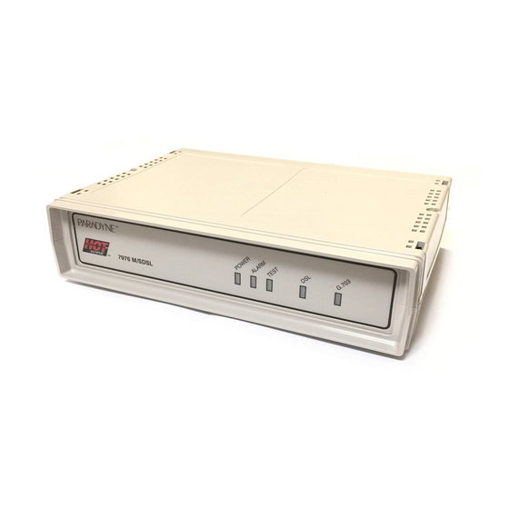
Paradyne HotWire 7976 User Manual
M/sdsl standalone termination unit with g.703 interface
Hide thumbs
Also See for HotWire 7976:
- Installation instructions manual (25 pages) ,
- User manual (166 pages) ,
- User manual (166 pages)

Related Manuals for Paradyne HotWire 7976


Summary of Contents for Paradyne HotWire 7976
- Page 1 HOTWIRE MODEL 7976 M/SDSL STANDALONE TERMINATION UNIT WITH G.703 INTERFACE USER’S GUIDE Document No. 7976-A2-GB20-10 August 1998...
- Page 2 Paradyne Corporation, 8545 126th Ave. N., Largo, FL 33773, or send e-mail to userdoc@eng.paradyne.com. Include the number and title of this document in your correspondence. Please include your name and phone number if you are willing to provide additional clarification. Printed on recycled paper August 1998 7976-A2-GB20-10...
- Page 3 Avoid using a telephone (other than a cordless type) during an electrical storm. There may be a remote risk of electric shock from lightning. — Do not use the telephone to report a gas leak in the vicinity of the leak. 7976-A2-GB20-10 August 1998 Important Information...
- Page 4 To Users of Digital Apparatus in Canada: This Class A digital apparatus meets all requirements of the Canadian interference-causing equipment regulations. Cet appareil numérique de la classe A respecte toutes les exigences du règlement sur le matérial brouilleur du Canada. August 1998 7976-A2-GB20-10...
-
Page 5: Table Of Contents
Contents About This Guide Document Purpose and Intended Audience Document Summary Product-Related Documents About the Model 7976 Standalone Termination Unit M/SDSL Overview Hotwire 7976 Termination Unit Features Network Configuration Front Panel LED Status Indicators Rear Panel Interface Connections SNMP Trap Support... - Page 6 Viewing Network Performance Statistics Viewing G.703 Performance Statistics Viewing Model 7976 Standalone Termination Unit LEDs Model 7976 Standalone Termination Unit LEDs ............
- Page 7 IP Addressing Example 7976-A2-GB20-10 .........
- Page 8 ......... . . August 1998 ....A-11 A-11 A-13 A-16 7976-A2-GB20-10...
-
Page 9: About This Guide
About This Guide Document Purpose and Intended Audience This guide contains information needed to set up, configure, and operate the Hotwire Model 7976 Multirate/Symmetric Digital Subscriber Line (M/SDSL) Standalone Termination Unit with G.703 interface and is intended for installers and operators. -
Page 10: Product-Related Documents
Defines acronyms and terms used in this document. Lists key terms, acronyms, concepts, and sections in alphabetical order. Document Title Hotwire 8776 M/SDSL Termination Unit User’s Guide Hotwire 8776 M/SDSL Termination Unit Installation Instructions Technical Manuals August 1998 7976-A2-GB20-10... -
Page 11: About The Model 7976 Standalone Termination Unit
About the Model 7976 Standalone Termination Unit M/SDSL Overview Hotwire maximize customer service areas by varying the DSL line rate. This ensures symmetric DSL connectivity over a wide range of telephone line distances and transmission line qualities. Hotwire M/SDSL products can transport at full or fractional payload rates over a 2-wire, full-duplex circuit over varying distances based on the conditions of the 2-wire loop. -
Page 12: Hotwire 7976 Termination Unit Features
About the Model 7976 Standalone Termination Unit Hotwire 7976 Termination Unit Features The Hotwire Model 7976 M/SDSL Standalone Termination Unit is an endpoint for the chassis-mounted Hotwire Model 8776 M/SDSL Termination Unit housed in the Hotwire 8600 or 8800 Digital Subscriber Line Access Multiplexer (DSLAM). -
Page 13: Network Configuration
This figure also shows a standalone-to-standalone configuration using either another Hotwire 7976 M/SDSL standalone unit with a G.703 interface or a Hotwire 7975 M/SDSL standalone unit with an EIA-530A interface. Frame... -
Page 14: Front Panel Led Status Indicators
About the Model 7976 Standalone Termination Unit Front Panel LED Status Indicators Figure 1-2 shows the front panel of the Model 7976 Standalone Termination Unit. For more information on front panel LEDs, refer to Chapter 4, Figure 1-2. Hotwire Model 7976 Standalone Termination Unit Front Panel... -
Page 15: Snmp Trap Support
SNMP Trap Support The Model 7976 Standalone Termination Unit supports traps as defined in RFC 1215. They may include variable-bindings specified in the following MIBs: MIB II (RFC 1573) – Defines the general objects for use with a network management protocol in TCP/IP internets and provides general information about the Model 7976 Standalone Termination Unit. - Page 16 About the Model 7976 Standalone Termination Unit This page intentionally left blank. August 1998 7976-A2-GB20-10...
-
Page 17: Using The Asynchronous Terminal Interface
Using the Asynchronous Terminal Interface User Interface Access You can communicate with the Hotwire Model 7976 Standalone Termination Unit with an asynchronous terminal interface (ATI) using one of the following methods: Direct connection through the COM port. Telnet session through the Embedded Operations Channel (EOC). -
Page 18: Initiating An Ati Session
IP address of the other user (if you are using the Management Serial port). If security is enabled on the Model 7976 Standalone Termination Unit and you used Telnet to access it directly (you did not log in through the MCC), the system prompts you for a login ID and password. - Page 19 View system status, diagnostic test results, statistics, LEDs, and device identity information. Select and cancel tests for the termination unit’s interfaces. Change the device identity, administer logins, download new firmware, or initiate a power-up reset of the termination unit. August 1998 Hotwire Model 7976 Exit...
- Page 20 Configuration Tests Config Loader Tests Network G.703 System Options August 1998 Control Change Download Reset Identity Code AutoRate Administer Apply Reset Logins Download Device Current Configuration Edit/Display Communication Management Port Communication Telnet Communication SNMP Session Protocol Option Traps 98-16071 7976-A2-GB20-10...
-
Page 21: Screen Work Areas
Using the Asynchronous Terminal Interface Configuration Load Configuration From NETWORK INTERFACE OPTIONS Margin Threshold: –3db Excessive Error Rate Threshold: 1E–5 AutoRate: Enable Peer IP Address: 111.255.255.000 Messages August 1998 Network Hotwire Model: 7976 Clear Clear MainMenu Exit LOS at Net, Pt n System... -
Page 22: Navigating The Screens
Move cursor up one field within a column on the same screen. Move cursor one character to the right if in edit mode. Move cursor one character to the left if in edit mode. Redraw the screen display, clearing information typed in but not yet entered. August 1998 7976-A2-GB20-10... -
Page 23: Screen Function Keys
Exit MainMenu PgDn PgUp ResetMon Save 7976-A2-GB20-10 Using the Asynchronous Terminal Interface Select . . . And press Enter to . . . F or f Clear far-end network statistics and refresh the screen. N or n Clear near-end network statistics and refresh the screen. -
Page 24: Switching Between Screen Work Areas
3. Tab to Exit (or type e or E) and press Enter. NETWORK INTERFACE OPTIONS Margin Threshold: –3db Excessive Error Rate Threshold: 1E–5 AutoRate: Disable DSL Line rate: Peer IP Address: 111.255.255.000 August 1998 Hotwire Model: 7976 Clear Î Î Clear Î Î MainMenu Exit 7976-A2-GB20-10... -
Page 25: Initial Startup And Configuration
Edit menus. Choosing the current or factory default configuration options or downloading configuration options from a TFTP server. Modifying current configuration options using the Configuration Edit/Display menu. Saving your changes. Downloading unit firmware from a TFTP server. 7976-A2-GB20-10 August 1998... -
Page 26: Connecting Power To The Unit
+24 Vdc power source, – 48 Vdc single source battery, or – 48 Vdc redundant source batteries (for power backup). Connecting the Unit to an Optional External DC Power Source Using the dc power cable, the Hotwire Model 7976 Standalone Termination Unit is capable of operating on a +24 Vdc power supply. NOTE: The E1 M/SDSL Unit is typically powered by the ac power module. -
Page 27: Connecting To The Network
Connecting to a System Terminal An optional system maintenance terminal may be attached to your Hotwire Model 7976 Standalone Termination Unit through the modular jack on the rear panel. The system maintenance terminal allows you to view the status of the unit, and change configuration options. -
Page 28: Entering Identity Information
2. Position the cursor in the System Location field. Enter the physical location of the unit. The maximum length of System Location is 128 characters. Control Change Identity IDENTITY lllQJ98-001 August 1998 Hotwire Model: 7976 Clear Clear Clear Î Î Î Î MainMenu Exit 7976-A2-GB20-10... -
Page 29: Choosing A Configuration Mode
Use the Configuration menu to select, display, or change configuration option settings. NOTE: The Model 7976 Standalone Termination Unit is pre-configured as an NTU. If you are using this unit as an NTU the following configuration options may not need to be performed. -
Page 30: Configuring The Unit Using The Internal Switches
4. After you enable the switchpacks, you must set the switches to your desired configuration. Refer to 5. Replace and secure the cover. 6. Power up the board to reset and enable the new configuration. to locate Switchpacks S1 and S2. Figure 3-1. Figure 3-1 Table August 1998 3-1. 7976-A2-GB20-10... -
Page 31: Switchpack Locations
Initial Startup and Configuration Switchpack Locations Use Figure 3-1 to locate Switchpacks S1 and S2. Switchpack S1 & S2 Front Rear 98-16073 Figure 3-1. Hotwire Model 7976 Standalone Termination Unit Switchpack Locations 7976-A2-GB20-10 August 1998... -
Page 32: Switchpack Definitions
OFF = Disable CRC-4 monitoring ON = Enable CRC-4 Controls whether Channel 16 contains signaling information or data. OFF = Channel 16 is used for signaling ON = Channel 16 is used for data Not used August 1998 Default in Bold 7976-A2-GB20-10... - Page 33 Select one of eight preset DSL line rates (refer to Table 3-3). All OFF = 2064 Not used Emergency Use Only – The Model 7976 has two banks of flash memory used to hold executable firmware This switch allows you to switch between the two versions of firmware. This switch is independent from the position of Switch 1 on Switchpack S1 (switchpack enable/disable).
-
Page 34: Accessing And Displaying Configuration Options
The selected configuration option set is loaded and the Configuration Edit/Display menu screen appears. The Configuration Loader screen is displayed allowing you to upload or download configurations from a TFTP server. August 1998 Hotwire Model: 7976 Î Î MainMenu Exit 7976-A2-GB20-10... -
Page 35: Configuration Edit/Display
Telnet Sessions Options, Table A-5 Communication Protocol Options, Table A-6 SNMP Traps Options, Table A-7 August 1998 Hotwire Model: 7976 Î Î Î Î MainMenu Exit To Configure the . . . DSL network interface on the unit. G.703 interface. -
Page 36: Configuring Autorate
NETWORK INTERFACE OPTIONS Margin Threshold: Excessive Error Rate Threshold: Autorate DSL Line Rate Peer IP Address: Rates, to set your DSL Line Rate and Payload August 1998 Hotwire Model: 7976 –3db 1E–6 Disable 111.255.255.000 Clear Î Î Clear MainMenu Exit... - Page 37 (time slots 0 and 16) or data only (time slot 0). Table 3-4. Fixed Rate Payload Rates and DSL Line Rates DSL Line Rate (kbps) 2064 1552 1040 7976-A2-GB20-10 Voice Mode Data Mode (G.703 to G.703) (G.703 to G.703) Maximum Maximum...
-
Page 38: Configuration Loader
CONFIGURATION LOADER Image File Name: 000.000.000.000 Destination: DSL Start Transfer: Yes Packets Sent: 0000000 Packets Received: 0000000 Bytes Sent: 0000000 Bytes Received: 0000000 Transfer Status: Transfer Pending Activate new configuration? No August 1998 Hotwire Model: 7976 Clear Clear MainMenu Exit 7976-A2-GB20-10... - Page 39 You must change these settings with the appropriate configuration menus after the new configuration is activated. See Table A-3, Appendix A, Configuration Option Tables . 7976-A2-GB20-10 System Options, and Table A-5, Telnet Sessions August 1998...
-
Page 40: Saving Configuration Options
Then . . . The configuration is saved. The Main Menu appears and changes are not saved. August 1998 Hotwire Model: 7976 Î Î Î Î MainMenu Exit 7976-A2-GB20-10... -
Page 41: Download Code
Download Code DOWNLOAD CODE Image File Name: 000.000.000.000 Destination: Start Transfer: Packets Sent: 0000000 Packets Received: 0000000 Bytes Sent: 0000000 Bytes Received: 0000000 Transfer Status: Transfer Pending August 1998 Initial Startup and Configuration Hotwire Model: 7976 Clear Clear MainMenu Exit 3-17... - Page 42 Initial Startup and Configuration This page intentionally left blank. 3-18 August 1998 7976-A2-GB20-10...
-
Page 43: Monitoring The Unit
Monitoring the Unit What to Monitor This chapter presents information on how to access and monitor Hotwire Model 7976 Standalone Termination Units on the E1 network. You can monitor Model 7976 Standalone Termination Unit operations by viewing: System and Test Status screens... -
Page 44: Viewing System And Test Status
System and Test Status SYSTEM AND TEST STATUS SELF-TEST RESULTS Passed ESC for previous menu PgDn Health and Status Messages. Self-Test Results Messages. August 1998 Hotwire Model: 7976 Page 1 of 1 TEST STATUS No Test Active MainMenu Exit Test Status 7976-A2-GB20-10... -
Page 45: Health And Status
EER at G.703, Pt 1 RAI (Remote Alarm Indication) at G.703 interface, Pt 1 Net Margin Threshold, Pt 1 7976-A2-GB20-10 What Message Indicates What To Do There are no problems detected. An LOS (Loss Of Signal) 1. Verify that the network cable is condition has been securely attached at both ends. - Page 46 ( yyyyyyyy ) to your service software. yyyyyyyy representative. indicates the 8-digit 2. Reset the Model 7976 hexadecimal failure code. Standalone Termination Unit to clear the condition and message. A firmware download was Repeat the download.
-
Page 47: Self-Test Results
The Unit failed to loop data on the G.703 on Port 1. The Model 7976 Standalone Termination Unit failed memory verification. A failure in the FPGA was detected. The unit failed to loop data between the G.703 Port and the DSL loop. -
Page 48: Test Status
A Repeater Loopback test is active on Port 1. A 511 Test and Monitor is active on the DSL Port 1 network interface. The Lamp Test is active, causing the LEDs on the front panel to light. Testing August 1998 7976-A2-GB20-10... -
Page 49: Viewing Network Error Statistics
Viewing Network Error Statistics The Model 7976 Standalone Termination Unit maintains error statistics on the network DSL interface for Port 1. Statistics are maintained for up to 96 15-minute intervals (24 hours). To view the Network Error Statistics, follow this menu selection sequence: Main Menu Î... -
Page 50: Viewing Network Performance Statistics
A 24-hour running total of the near- and far-end performance statistics. Status Performance Network Performance Statistics NETWORK PERFORMANCE STATISTICS ––Mrgn–– ––XmtPw– Near Far Near Far PgDn August 1998 Hotwire Model: 7976 Payload Rate: 1984 Kbps DSL Line Rate: 2064 Kbps ––RxGn–– –Complete– Near Far Near Far MainMenu Exit 7976-A2-GB20-10... - Page 51 RxGn: The receiver gain level. Complete: Whether the interval register contains data for a complete 900-second interval. 7976-A2-GB20-10 Contains . . . The number of seconds which have elapsed in the current 15-minute interval. Maximum value is 900 seconds (15 minutes).
-
Page 52: Viewing G.703 Performance Statistics
LOF events. 4-10 Status Performance G.703 Performance Statistics G.703 PERFORMANCE STATISTICS ––ES–– ––UAS–– ––SES–– 00000 00000 PgDn ClrStats August 1998 Hotwire Model: 7976 Error Events Counter: 0000 ––BES–– ––LOF–– –Status– none none none none none none none 00000 MainMenu Exit... - Page 53 Current Interval Interval xx Error Events Counter 7976-A2-GB20-10 Contains . . . The number of seconds which have elapsed in the current 15-minute interval. Maximum value is 900 seconds (15 minutes). This counter resets every 15 minutes. Performance data for the current 15 minutes.
-
Page 54: Viewing Model 7976 Standalone Termination Unit Leds
Monitoring the Unit Viewing Model 7976 Standalone Termination Unit LEDs The Model 7976 Standalone Termination Unit LEDs can be viewed on the Display LEDs status screen. This ATI status screen is available locally and remotely. The three groups of LEDs are: General LEDs display the status of the unit G.703 LEDs provide the status of the G.703 interface... -
Page 55: Model 7976 Standalone Termination Unit Leds
Model 7976 Standalone Termination Unit LEDs The following table contains a description of the LEDs on the Model 7976 Standalone Termination Unit front panel. Type General G.703 7976-A2-GB20-10 7976 M/SDSL LED is . . . Indicating . . . POWER Green Unit has power. - Page 56 Monitoring the Unit This page intentionally left blank. 4-14 August 1998 7976-A2-GB20-10...
-
Page 57: Accessing The Test Menu
To abort all current tests excluding G.703 and Network-initiated loopback tests. An aborted test may continue to run for a few seconds as the abort command is sent to the remote end and processed. August 1998 Hotwire Model: 7976 Î Î Î Î MainMenu Exit... -
Page 58: Running Network Tests
Test Network & G.703 Tests NETWORK & G.703 TESTS Command Status Results Start Inactive 00:00:00 Start Inactive 00:00:00 Start Inactive 00:00:00 Start Inactive 00:00:00 Send Inactive 00:00:00 Stop Active hh:mm:ss - Errors 99999+ August 1998 Model: 7976 MainMenu Exit 7976-A2-GB20-10... -
Page 59: Line Loopback
3. To manually stop the test, verify that the cursor is positioned at the Stop command. 4. Press Enter. Line Loopback cannot be started when a Repeater Loopback, DTE Loopback, Remote DCLB, or network-initiated Line Loopback is in progress. 7976-A2-GB20-10 Framer Framer August 1998 Testing G.703... -
Page 60: Repeater Loopback
4. Press Enter. A Repeater loopback cannot be started when any other loopback test is in progress. NOTE: Activating the Repeater loopback test causes the EOC to be lost to the remote unit. Framer Framer August 1998 G.703 Port 98-15999 7976-A2-GB20-10... -
Page 61: Dte Loopback
4. Press Enter. A DTE loopback cannot be started when any other loopback test is in progress. NOTE: Activating the DTE loopback test causes the EOC to be lost to the remote unit. 7976-A2-GB20-10 Transceiver Framer Framer August 1998 Testing G.703... -
Page 62: Send Remote Line Loopback
10 seconds. You cannot stop the Send Remote Line Loopback test manually. The Send Remote Line Loopback cannot be started when any other loopback or a Send and Monitor 511 test is active on the network interface. Remote Transceiver Transceiver Framer August 1998 G.703 Port Framer 98-16001 7976-A2-GB20-10... -
Page 63: Send And Monitor 511
When a Send and Monitor 511 test is active, a count of bit errors is displayed next to the test duration, and the ResetMon virtual function key is available for use. Type r or R or select the ResetMon virtual function key to reset the error count. 7976-A2-GB20-10 Pattern Pattern... -
Page 64: Device Tests
3. To stop the lamp test, position the cursor at the Stop command. 4. Press Enter. Test Device Tests DEVICE TESTS Test Command Status Lamp Test: Start Inactive August 1998 Hotwire Model: 7976 Î Î MainMenu Exit 7976-A2-GB20-10... -
Page 65: Ending An Active Test
Command Complete appears when all tests on all interfaces have been terminated. An aborted test may continue to run for a few seconds as the abort command is sent to the remote end and processed. 7976-A2-GB20-10 System Options. August 1998... - Page 66 Testing This page intentionally left blank. 5-10 August 1998 7976-A2-GB20-10...
-
Page 67: Messages And Troubleshooting
Messages and Troubleshooting Overview There are many resources available to assess the status of the device and contribute to problem resolutions. Refer to the following sections: Configuring SNMP Traps Device Messages Troubleshooting 7976-A2-GB20-10 August 1998... -
Page 68: Configuring Snmp Traps
7976 Standalone Termination Unit by entering an IP address and network destination for each SNMP manager specified. Select the type of SNMP traps to be sent from the Model 7976 Standalone Termination Unit. To configure SNMP Traps, follow this menu selection sequence:... -
Page 69: Device Messages
Invalid – [ Test ] Already Active Invalid Test Combination Invalid entry at cursor (1...223, excluding 127) 7976-A2-GB20-10 Messages and Troubleshooting What Message Indicates What To Do The operator requested that If configuration options are to be configuration options be... - Page 70 Wait until the other test ends and message clears. Cancel all tests from the Test screen. Stop the test from the same screen the test was started from. An IP address of all zeroes Enter a valid, non-zero IP was entered. address. August 1998 7976-A2-GB20-10...
-
Page 71: Troubleshooting
Troubleshooting This Model 7976 Standalone Termination Unit is designed to provide you with many years of trouble-free service. If a problem occurs, however, refer to Table 6-2 for possible solutions. Table 6-2. Troubleshooting (1 of 2) Symptom Alarm LED is on. - Page 72 Check the far-end Health and An alarm condition exists Status messages. in the far-end unit. The unit has detected an Reset the unit and try again. internal hardware failure. Contact your service representative. August 1998 Testing 7976-A2-GB20-10...
-
Page 73: Security
Security Overview The Model 7976 Standalone Termination Unit provides several methods of security by limiting user access to the ATI through option settings. You can: Enable the Telnet Login Required option. Limit the access by setting a Session Access Level option of Operator for the Telnet Session. -
Page 74: Creating A Login
Creating a Login Logins apply to the terminal directory connected to the communication port or Telnet access directly to the ATI of the Model 7976 Standalone Termination Unit. Six login ID/password combinations are available. Each Login ID and Password must be unique and include an access level. - Page 75 6. If additional logins are required, repeat 7. When all logins are entered, press Esc to return to the Administer Logins screen. 8. Select Save and press Enter. 7976-A2-GB20-10 Enter . . . 1 to 10 ASCII printable characters (hex21 through 7E). Blanks are not allowed.
-
Page 76: Deleting A Login
2. Reset the unit, then immediately and repeatedly press Enter at a rate of about 1 press per second until the System Paused screen appears. 3. Tab to the desired method, and enter yes (or y) for the selected prompt. Control Administer Logins August 1998 7976-A2-GB20-10... - Page 77 COM port rate returning to its configured rate. The termination unit resets itself, going through a Self-Test. Connectivity is restored and the Main Menu screen appears. 7976-A2-GB20-10 Then . . . Port type is set to Terminal Data Rate (kbps) is set to 9.6...
- Page 78 Security This page intentionally left blank. August 1998 7976-A2-GB20-10...
-
Page 79: Ip Addressing
Peer IP address of the M/SDSL Network interface menu. The standalone termination unit can also be assigned an IP address and subnet mask for the COM port. Once an address is assigned, you can manage the Model 7976 Standalone Termination Unit’s ATI to assign an: IP address for each NMS to act as a trap manager. -
Page 80: Ip Addressing Example
MCC Base Address = 126.35.1.1 MCC Base Subnet Mask = 255.255.0.0 7976 LTU IP Address = 126.35.7.1 LTU Peer IP Address = 126.35.7.2 Peer IP Address Assignments The Peer IP Address refers to the IP address of the unit configured as an NTU. -
Page 81: Overview
Options Communication Port Management Communication NOTE: All changes to configuration options must be saved. Refer to Configuration Options 7976-A2-GB20-10 To Access the . . . Network Interface Options, Table A-1 G.703 Interface Options, Table A-2 System Options, Table A-3 Communication Port... -
Page 82: Network Interface Options Menu
Disable – The LTU Line rate is user selectable and is based on the DSL Line Rate selected. Configuration Current Configuration NETWORK INTERFACE OPTIONS Margin Threshold: Excessive Error Rate Threshold: AutoRate: DSL Line Rate: Peer IP Address: August 1998 Network Hotwire Model: 7976 –3db 1E–6 Disable 400 Kbps 111.255.255.000 Clear Î Î Clear MainMenu Exit 7976-A2-GB20-10... - Page 83 [ASCII Text] – Enter a maximum of 128 characters. All printable ASCII characters except ^ (caret) are allowed. Clear – Clears the field. 7976-A2-GB20-10 For associated payload rates refer to Table 3-4, Rates, in Chapter 3, Initial Startup and Configuration .
-
Page 84: G.703 Interface Options Menu
Network Interface. Configuration Load Configuration From G.703 INTERFACE OPTIONS Line Coding: HDB3 Line Framing: noCRC4 Time Slot 16: Signaling Send (AIS) on Network Failure: Enable Primary Clock Source: G703 Pt1 August 1998 G.703 Hotwire Model: 7976 Î Î MainMenu Exit 7976-A2-GB20-10... - Page 85 Internal – The clock source is derived from the internal oscillator. G.703 Pt1 – The clock source is derived from the G.703 interface. 7976-A2-GB20-10 For associated DSL line rates and payload rates refer to Table 3-4, Rate Payload Rates and DSL Line Rates, in Chapter 3, Initial Startup and Configuration .
-
Page 86: System Options Menu
DSL Mode: Test Timeout: Test Duration (min): G.703 Line Termination Changing this option will reset the card. Running Network Tests August 1998 System Hotwire Model: 7976 Enable 120 Ohm Î Î Î Î MainMenu Exit in Chapter 5, Testing . 7976-A2-GB20-10... - Page 87 Possible Settings: 75 ohms, 120 ohms Default Setting: 120 ohms Specifies the impedance of the G.703 interface 75 ohms – The G.703 interface impedance is 75 ohms unbalanced. 120 ohms – The G.703 interface impedance is 120 ohms balanced. 7976-A2-GB20-10 August 1998...
-
Page 88: Communication Port
Port Use: Port Type: Data Rate (Kbps): Character Length: Parity: Stop Bits: Ignore Control Leads: Login Required: Port Access Level: Inactivity Timeout: Disconnect Time (Minutes): August 1998 Communication Hotwire Model: 7976 Terminal Asynchronous None Enable Enable Administrator Enable MainMenu Exit 7976-A2-GB20-10... - Page 89 2 – Two stop bits used. Ignore Control Leads (Terminal Use Only) Possible Settings: Disable, DTR Default Setting: Disable Specifies whether DTR is used. Disable – Control leads are treated as standard. DTR – DTR is ignored. 7976-A2-GB20-10 August 1998...
-
Page 90: August 1998 7976-A2-Gb20
Telnet session. Administrator – This is the higher access level, permitting full control of the Model 7976 Termination Unit. Access level is determined by the Login ID. If Telnet Login Required is disabled, the session access level is Administrator. Operator – This is the lower access level, permitting read-only access to status and configuration screens. -
Page 91: Management And Communication Options Menu
Options, Table A-7 Configuration Load Configuration From Telnet Session TELNET SESSIONS OPTIONS Telnet Session: Telnet Login Required: Session Access Level: Inactivity Timeout: Disconnect Time (Minutes) August 1998 Configuration Option Tables Hotwire Model: 7976 Enable Enable Administrator Enable Î Î MainMenu Exit A-11... - Page 92 ATI Access Levels Administrator – This is the higher access level, permitting full control of the Model 7976 Termination Unit. Access level is determined by the Login ID. If Telnet Login Required is disabled, the session access level is Administrator.
-
Page 93: Communication Protocol Options
COMMUNICATION PROTOCOL OPTIONS Node IP Address: 000.000.000.000 Node Subnet Mask: 000.000.000.000 Default Network Destination: None Communication Port IP Address: 000.000.000.000 Subnet Mask: 000.000.000.000 Link Protocol: August 1998 Configuration Option Tables Hotwire Model: 7976 Clear Clear Clear Clear MainMenu Exit A-13... - Page 94 Communication Port. The range for the first byte is 000 to 223, with the exception of 127. The range for the remaining three bytes is 000 to 255. Clear – Clears the IP address and sets to all zeros. A-14 August 1998 7976-A2-GB20-10...
- Page 95 Communication Port Options menu is set to Net Link. PPP – Defines Point-to-Point protocol for the link layer protocol for the network communication link. SLIP – Serial Line IP Protocol for the link layer protocol for the network communication link. 7976-A2-GB20-10 Configuration Option Tables August 1998 A-15...
-
Page 96: Snmp Traps Options
Configuration Option Tables SNMP Traps Options SNMP configuration options allow you to specify the information necessary to support the Model 7976 termination unit SNMP traps. To access the SNMP Traps Options screen, follow this menu selection sequence: Main Menu Management and Communication Î... - Page 97 Determines if SNMP traps are generated for enterprise-specific events. Enable – SNMP traps are generated for enterpriseSpecific events. NOTE: Disable – No enterprise-specific event traps are sent. 7976-A2-GB20-10 Refer to Appendix B, Standards Compliance for SNMP Traps Refer to Enterprise Specific Traps in Appendix B, Standards Compliance for SNMP Traps .
-
Page 98: Linkup And Linkdown
Disable – No linkUp or linkDown SNMP traps are generated. Up – A linkUp trap is generated when the Model 7976 Termination Unit recognizes that one of the communication interfaces is operational. Down – A linkDown trap is generated when the Model 7976 Termination Unit recognizes a failure in one of the communication interfaces. -
Page 99: Standards Compliance For Snmp Traps
SNMP Trap warmStart authenticationFailure SNMP Trap authenticationFailure 7976-A2-GB20-10 Description Possible Cause The unit has reinitialized Reset command. itself. Power disruption. The trap is sent after the unit resets and stabilizes. There are no variable-bindings. -
Page 100: Linkup And Linkdown
This object contains the same value as ifAdminStatus. fType (RFC 1573) This object is the type of interface: – e1(19) Used for the G.703 E1 interface. COM Port SDSL E1 Interface, Port 1 G.703 Interface, Port 1 August 1998 7976-A2-GB20-10... -
Page 101: Enterprise-Specific Traps
Change(6) enterpriseFallback AutoRate(13) enterpriseTestStop(105) enterpriseFallback AutoRateClear(113) 7976-A2-GB20-10 Standards Compliance for SNMP Traps Description Possible Cause A failure of the currently The configured clock source configured primary clock is no longer operational. If source for the unit has the configured clock source been detected. - Page 102 This object contains the same value as ifAdminStatus. fType (RFC 1573) This object is the type of interface: – e1(19) Used for the G.703 E1 interface. COM Port SDSL E1 Interface, Port 1 G.703 Interface, Port 1 August 1998 7976-A2-GB20-10...
- Page 103 E1 network and user data port interfaces. The specific tests and variable-bindings are described in the following table: Interface SDSL Network G.703 7976-A2-GB20-10 Standards Compliance for SNMP Traps enterpriseTestStart/Stop Variable-Bindings ifIndex (RFC 1573) ifAdminStatus (RFC 1573)
- Page 104 Standards Compliance for SNMP Traps August 1998 7976-A2-GB20-10...
-
Page 105: Cables And Pin Assignments
Cables and Pin Assignments Overview The following sections provide pin assignments: E1 Network Interface Cable DSL Network Interface Cable COM Port Interface Cable Power Input Connector Optional Power Cable 7976-A2-GB20-10 August 1998... - Page 106 Table C-1. E1 120-Ohm Balanced Interface Connector Signal Receive Ring Receive Tip Receive Shield Transmit Ring Transmit Tip Transmit Shield Figure C-1. E1 120-Ohm Network Interface Adapter Cable (Optional) (Table Pin Number (Feature Number 3100-F1-517) August 1998 C-1, Figure C-1). 7976-A2-GB20-10...
- Page 107 The DSL line interface cable is a 20-foot, 24 AWG solid, 2-twisted-pair cable that is RJ48C-to-RJ48C 8-Pin Plug Pin #8 Pin #1 Unused Unused Ring Figure C-2. DSL Network Interface Cable with RJ48C Connector 7976-A2-GB20-10 (Table C-2, Figure C-2). Table C-2. DSL Network Interface Connector Signal Ring 97-15884 RJ48C...
-
Page 108: Com Port Interface Cable
8-position modular plug keyed connector and a DB9 socket connector (Figure C-3). The COM port connector is an 8-position keyed modular jack (Table C-3). The data signals on this port are referenced to a DTE interface. Figure C-3. COM Port-to-PC Cable (Feature Number 7900-F1-507) 98-15886 August 1998 7976-A2-GB20-10... - Page 109 Reserved for future use DCE Received Data Signal Ground DCE Transmit Data DCE Data Terminal Ready DCE Carrier Detect DCE Request-to-Send Reserved for future use 7976-A2-GB20-10 Cables and Pin Assignments Direction Pin Number to DTE (Out) to DTE (Out) — from DTE (IN)
-
Page 110: Power Input Connector
DC power source. Figure C-4. DC Power Cable (Feature Number 7900-F1-506) Pin Number Figure C-4 shows the wire colors. Black Green Earth Ground White Orange +24 Vdc Blue 98-14158-01 August 1998 Table C-4. 7976-A2-GB20-10... - Page 111 Length 9.4 inch (24.9 cm) Approximately 1.25 lbs. (0.6 kg) Refer to the equipment’s label for approvals on product. The Model 7976 Termination Unit contains a DC-to-DC converter that requires +24V power input. The +24V power is distributed through a universal power supply supplied with the unit.
- Page 112 Technical Specifications August 1998 7976-A2-GB20-10...
- Page 113 Data Set Ready. A signal from the modem to the DTE that indicates the modem is turned ON and connected to the DTE. Data Terminal Equipment. The equipment, such as a computer or terminal, that provides data in the form of digital signals for transmission. 7976-A2-GB20-10 August 1998 GL-1...
- Page 114 Internet Protocol. An open networking protocol used for internet packet delivery. IP address Internet Protocol address. The address assigned to an internet host. Local Area Network. A privately owned and administered data communications network limited to a small geographic area. GL-2 August 1998 7976-A2-GB20-10...
- Page 115 Telnet Virtual terminal protocol in the Internet suite of protocols. Allows the user of one host computer to log into a remote host computer and interact as a normal terminal user for that host. 7976-A2-GB20-10 August 1998 Glossary GL-3...
- Page 116 Conversely, the modem uses Pin 2 to receive data from the DTE. UNIX An operating system developed at AT&T Bell Laboratories and since used as the basis of similar operating systems. Wide Area Network. A network that spans a large geographic area. GL-4 August 1998 7976-A2-GB20-10...
- Page 117 4-4 Circuit Identifier, A-3 Clock Failed, status message, 4-4 COM port, resetting, 7-4 COM port settings, 3-3 Communication Port, A-8 7976-A2-GB20-10 Configurating AutoRate, 3-12 Configuring the unit, 3-1 configuration example, 1-3 option tables, A-1 configuration changes, saving, 3-16...
- Page 118 Net Margin Threshold, status message, 4-3 network interface options, A-2 tests, 5-2 G.703 Failed, self-test result, 4-5 network interface, pin assignments, C-2– C-6 network interface options, A-3 Network-Initiated DCLB, A-5 NMS, SNMP connectivity, 8-1 no test active status message, 4-6 August 1998 7976-A2-GB20-10...
- Page 119 2-7 screens, for user interface, 2-1– 2-6 SDSL Mode, A-6 security, 7-1 self-test results, 4-5 Send and Monitor 511, 5-7 7976-A2-GB20-10 Send Remote Line Loopback, 5-6 size of unit, D-1 SNMP trap options, 6-2 traps, B-1 start-up, ATI, 2-1...
- Page 120 Index UNIX, TFTP server on, 3-14 user interface, 3-3 async terminal, 2-1 how to access, 2-1 resetting/restoring access, 7-4 IN-4 virtual function keys, 2-7 warmStart, B-1 weight of unit, D-1 August 1998 7976-A2-GB20-10...