Dürkopp Adler 52 i Series Operating Instructions Manual
Hide thumbs
Also See for 52 i Series:
- Service instructions manual (84 pages) ,
- Operating instructions manual (120 pages)
Table of Contents
Advertisement
Quick Links
Advertisement
Table of Contents

Related Manuals for Dürkopp Adler 52 i Series


Summary of Contents for Dürkopp Adler 52 i Series
- Page 1 52Xi 52Xi-75 Operating Instructions...
- Page 2 IMPORTANT READ CAREFULLY BEFORE USE KEEP FOR FUTURE REFERENCE All rights reserved. Property of Dürkopp Adler GmbH, and protected by copyright. Any reuse of these contents, including extracts, is prohibited without the prior written approval of Dürkopp Adler GmbH. Copyright © Dürkopp Adler GmbH 2021...
-
Page 3: Table Of Contents
Table of Contents About these instructions ..............5 For whom are these instructions intended? .......... 5 Representation conventions – symbols and characters ......6 Other documents ................... 7 Liability ....................8 Safety....................9 Basic safety instructions ................ 9 Signal words and symbols used in warnings........10 Machine description................ - Page 4 Table of Contents 4.13.2 Key control panel................. 54 4.14 Puller ....................55 4.14.1 Control with hand lever................ 55 4.14.2 Puller electropneumatic control ............56 4.15 Sewing....................58 Maintenance..................61 Cleaning ....................62 Lubricating ................... 64 5.2.1 Lubricating the machine head ............. 65 5.2.2 Hook lubrication...................
- Page 5 Table of Contents Performing a test run ................ 96 Decommissioning ................97 Disposal ..................... 99 Troubleshooting ................101 13.1 Customer Service ................101 13.2 Errors in the sewing process ............. 102 Technical parameters ..............105 Appendix ..................107 Operating Instructions 52Xi, 52Xi-75 - 00.0 - 10/2021...
- Page 6 Table of Contents Operating Instructions 52Xi, 52Xi-75 - 00.0 - 10/2021...
-
Page 7: About These Instructions
About these instructions About these instructions These instructions have been prepared with utmost care. They contain information and notes intended to ensure long-term and reliable operation. Should you notice any discrepancies or if you have improvement requests, then we would be glad to receive your feedback through Customer Service (... -
Page 8: Representation Conventions - Symbols And Characters
About these instructions Representation conventions – symbols and characters Various information in these instructions is represented or high- lighted by the following characters in order to facilitate easy and quick understanding: Proper setting Specifies proper setting. Disturbances Specifies the disturbances that can occur from an incorrect setting. Cover Specifies which covers must be disassembled in order to access the components to be set. -
Page 9: Other Documents
About these instructions Information Additional information, e.g. on alternative operating options. Order Specifies the work to be performed before or after a setting. References Reference to another section in these instructions. Safety Important warnings for the user of the machine are specifically marked. -
Page 10: Liability
About these instructions Liability All information and notes in these instructions have been compiled in accordance with the latest technology and the applicable stan- dards and regulations. Dürkopp Adler cannot be held liable for any damage resulting from: • Breakage and damage during transport •... -
Page 11: Safety
Safety Safety This chapter contains basic information for your safety. Read the instructions carefully before setting up or operating the machine. Make sure to follow the information included in the safety instruc- tions. Failure to do so can result in serious injury and property damage. -
Page 12: Signal Words And Symbols Used In Warnings
Safety All the warnings and safety signs on the machine must always be in legible condition. Do not remove! Missing or damaged warnings and safety signs must be replaced immediately. Requirements Only qualified specialists may: to be met by • set up the machine the personnel •... - Page 13 Safety CAUTION (with hazard symbol) If ignored, moderate or minor injury can result CAUTION (with hazard symbol) If ignored, environmental damage can result NOTICE (without hazard symbol) If ignored, property damage can result Symbols The following symbols indicate the type of danger to personnel: Symbol Type of danger General...
- Page 14 Safety Examples Examples of the layout of warnings in the text: DANGER Type and source of danger! Consequences of non-compliance. Measures for avoiding the danger. This is what a warning looks like for a hazard that will result in serious injury or even death if ignored. WARNING Type and source of danger! Consequences of non-compliance.
- Page 15 Safety NOTICE Type and source of danger! Consequences of non-compliance. Measures for avoiding the danger. This is what a warning looks like for a hazard that could result in property damage if ignored. CAUTION Type and source of danger! Consequences of non-compliance.
- Page 16 Safety Operating Instructions 52Xi, 52Xi-75 - 00.0 - 10/2021...
-
Page 17: Machine Description
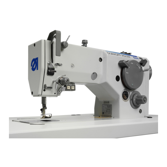
Machine description Machine description • A flatbed single-needle machine. • It sews a double-thread zig-zag lockstitch. • It has a bi-directional drop feed. • The machine is equipped with a horizontal hook. • Wick lubrication. • There is an automatic bobbin winder on the machine arm. •... -
Page 18: Proper Use
Machine description Proper use WARNING Risk of injury from live, moving and cutting parts as well as from sharp parts! Improper use can result in electric shock, crushing, cutting and punctures. Follow all instructions provided. NOTICE Non-observance will lead to property damage! Improper use can result in material damage at the machine. -
Page 19: Subclasses
Machine description Subclasses 3.2.1 Machine with short arm Thread Class and subclass Hook Foot lifting Backtacking trimming 523i 411001 523i 447001 524i 811001 524i 847001 525i 811001 525i 847001 525i 911001 525i 947001 527i 811001 527i 847001 527i 911001 527i 947001 Operating Instructions 52Xi, 52Xi-75 - 00.0 - 10/2021... -
Page 20: Machine With Long Arm
Machine description 3.2.2 Machine with long arm Thread Class and subclass Hook Foot lifting Backtacking trimming 525i 811201 525i-811-75 525i 847201 525i-847-75 525i 811202 525i-811-75-66 525i 847202 525i-847-75-66 Operating Instructions 52Xi, 52Xi-75 - 00.0 - 10/2021... -
Page 21: Sewing Equipment
Machine description Sewing equipment 3.3.1 Machine with short arm Throat plate Feed dog Foot „ ‚ Stichplatte Transporteur Fuß ƒ … † ‡ ˆ E-Nr. For Subclass / Für Unterklasse E-No. Abb.-Nr. Use / Verwendungszweck Fig.No. 523 E 069 523i 411001;... - Page 22 Machine description Throat plate Feed dog Foot „ ‚ Stich platte Transporteur Fuß ƒ ‡ ˆ … † E-Nr. Für Unterklasse / For Subclass E-No. Abb.-Nr. Verwendungszweck / Use Fig.No. 525 E 075 524i 811001; 524i 847001; 525i 811001; 525i 847001;...
- Page 23 Machine description Throat plate Feed dog Foot „ ‚ Stich platte Transporteur Fuß ƒ † ‡ ˆ … E-Nr. Für Unterklasse / For Subclass E-No. Abb.-Nr. Verwendungszweck / Use Fig.No. 527 E 060 525i 811001; 525i 847001; 525i 911001; 525i 947001;...
-
Page 24: Machine With Long Arm
Machine description 3.3.2 Machine with long arm Throat plate Feed dog Foot „ ‚ Stichplatte Transporteur Fuß … ƒ † ‡ ˆ E-Nr. For Subclass / Für Unterklasse E-No. Abb.-Nr. Use / Verwendungszweck Fig.No. 525 E003 525i 811-75; 525i 847-75; 525i 811-75-66; 525i 847-75-66 Sewing equipment for two needle sewing, needle gauge 3 mm, 4 mm and 5 mm,... - Page 25 Machine description Throat plate Feed dog Foot „ ‚ Stich platte Transporteur Fuß ƒ ‡ ˆ … † E-Nr. Für Unterklasse / For Subclass E-No. Abb.-Nr. Verwendungszweck / Use Fig.No. 527 E 023 525i 811-75; 525i 847-75; 525i 811-75-66; 525i 847-75-66 Sewing equipment for sewing butt seams, 3-lined feed dog, needle size Nm 110-130, stitch length...
- Page 26 Machine description Throat plate Feed dog Foot „ ‚ Stich platte Transporteur Fuß ƒ † ‡ ˆ … E-Nr. Für Unterklasse / For Subclass E-No. Abb.-Nr. Verwendungszweck / Use Fig.No. 527 E 060 525i 811-75; 525i 847-75; 525i 811-75-66; 525i 847-75-66 Sewing equipment for two needle cordin seams with or without filler cord, 3-lined feed dog,...
- Page 27 Machine description Throat plate Feed dog Foot „ ‚ Stich platte Transporteur Fuß ƒ † ‡ ˆ … E-Nr. Für Unterklasse / For Subclass E-No. Abb.-Nr. Verwendungszweck / Use Fig.No. 525 E081 525i 847-75; 525i 847-75-66 Puller - S981 009060, S981 009061, S981 009064, S981 009065 Sewing equipment for sewing butt seams, 3-lined feed dog, needle size Nm 110-130, stitch length...
-
Page 28: Optional Equipment
Machine description Optional equipment 3.4.1 Machine with short arm Order No. Optional equipment S794 222013 Sewing light diode including transformer ... -
Page 29: Machine With Long Arm
Machine description 3.4.2 Machine with long arm Order No. Optional equipment S794 222013 Sewing light diode including transformer S981 069441 Knee lever S980 035456 Gauge ... - Page 30 Machine description Order No. Optional equipment 0933 005737 Feed roller steel/88 teeth- width 15 mm 0933 005738 A Feed roller steel/44 teeth- width 15 mm S981 052125 Foot lift and backtacking pneum. S981 052126 Needle cooling - only for machine with Puller ...
- Page 31 Machine description Cams for shape sewing for machine 525i Commercial Order number Quantity Quantity sewing Pattern width Single-needle Double-needle Marking sewing points/ points/pattern 1 cam turn Stitch length Z 037 S080 674219 4400 3800 Z 038 S080 674113 4,5 - 10 3800 3400 Z 039...
- Page 32 Machine description Cams for shape sewing for machine 525i-75 Commercial Order number Quantity Quantity sewing Pattern width Single-needle Double-needle Marking sewing points/ points/pattern 1 cam turn Stitch length Z 037 S080 674219 2500 2500 Z 038 S080 674113 4,5 - 10 2500 2500 Z 039...
- Page 33 Machine description Cams for shape sewing for machine 525i-75-66 Commercial Order number Quantity Quantity sewing Pattern width Single-needle Double-needle Marking sewing points/ points/pattern 1 cam turn Stitch length Z 037 S080 674219 2000 2000 Z 038 S080 674113 4,5 - 10 2000 2000 Z 039...
-
Page 34: Declaration Of Conformity
Machine description Declaration of Conformity The machine complies with European regulations ensuring health, safety, and environmental protection as specified in the declara- tion of conformity or in the declaration of incorporation. Operating Instructions 52Xi, 52Xi-75 - 00.0 - 10/2021... -
Page 35: Operation
Operation Operation The operating sequence consists of several different steps. Fault-free operation is necessary in order to achieve a good sewing result. Preparing the machine for operation WARNING Risk of injury from moving, cutting and sharp parts! Crushing, cutting and punctures are possible. If possible, make preparations only when the machine is switched off. -
Page 36: Switching On And Off The Machine
Operation Switching on and off the machine For switching on/off use the main switch (3). Important When you switch on the machine must not be under the foot presser sewn material! Pic. 1: Switching on and off the machine and sewing lamp ①... -
Page 37: Inserting/Replacing The Needle
Operation Inserting/replacing the needle WARNING Risk of injury from needle and moving parts! Switch off the machine before you insert or replace the needle. Do not touch the tip of the needle. Order Adjust the distance between the needle and the hook point after replacing to a different needle thickness (... -
Page 38: Machine 523I, 524I, 525I - Needle System 134
Operation 4.3.1 Machine 523i, 524i, 525i - needle system 134 Pic. 2: Needle inserting/replacing ① ② ③ ④ (1) - Needle bar (3) - Needle (2) - Screw (4) - Scarf Turn the handwheel until the needle bar (1) reaches the upper end position. -
Page 39: Machine 527I - Needle System 134; 134-35
Operation 4.3.2 Machine 527i - needle system 134; 134-35 Pic. 3: Needle inserting/replacing ① ② ③ ⑤ ④ (1) - Needle bar (4) - Scarf (2) - Screw (5) - Screw (3) - Needle Turn the handwheel until the needle bar (1) reaches the upper end position. -
Page 40: Threading The Needle Thread
Operation Threading the needle thread WARNING Risk of injury from needle and moving parts! Switch off the machine before threading the thread. Pic. 4: Threading the needle thread Fit the thread reel to the reel stand. Threading the thread according to the picture. Operating Instructions 52Xi, 52Xi-75 - 00.0 - 10/2021... -
Page 41: Winding The Hook Thread
Operation Winding the hook thread Proper setting • Safety spring for bobbin (1) must be in hole (2). • Safety spring for bobbin with increased thread supply (3) must be in hole (4). Pic. 5: Winding the hook thread 1 ①... - Page 42 Operation Pic. 6: Winding the hook thread 2 ⑤ ⑥ ⑦ ⑧ ⑨ ⑧ (5) - Arrow (8) - Knife (6) - Arrow (9) - Arrow (7) - Winder lever Fit the thread reel to the reel stand. Feed the thread according to the picture and wind 5 times around the bobbin.
-
Page 43: Changing The Bobbin And Thread Hook Threading
Operation Changing the bobbin and thread hook threading WARNING Risk of injury from needle and moving parts! Switch off the machine before changing the bobbin. Pic. 7: Changing the bobbin and thread hook threading ⑧ ⑦ ⑥ ⑤ ① ② ③... -
Page 44: Thread Tension
Operation Thread tension Together with the hook thread tension, the needle thread tension influences the final seam pattern. With thin sewing material, ex- cessive thread tension can lead to undesired gathering and thread breakage. Proper setting If the tension of needle thread and hook thread is identical, the thread interlacing lies in the middle of the sewing material. -
Page 45: Setting The Needle Thread Tension
Operation 4.7.1 Setting the needle thread tension Pic. 9: Setting the needle thread tension ① ② (1) - Auxiliary tensioner (2) - Main tensioner Increasing the tension: Turn the regulating knob clockwise. Reducing the tension: Turn the regulating knob counterclockwise. Setting the auxiliary tensioner (1) Adjust the auxiliary tensioner (1) so that it has as small tension as possible, but high enough so as the thread cannot be pulled out... -
Page 46: Setting The Hook Thread Tension
Operation 4.7.2 Setting the hook thread tension WARNING Risk of injury from needle and moving parts! Switch off the machine before setting the hook thread tension. Pic. 10: Setting the hook thread tension ① ② ③ ④ ⑤ ⑥ ⑧ ⑦... - Page 47 Operation Setting the tension spring (2) Remove the bobbin case (5) from the machine and insert a full-wound bobbin (4). Do a complete threading according to picture (A). Regulate the spring (2) pressure with a screw (3) so that the thread tension is in balance with the case and bobbin weight.
-
Page 48: Foot Lifting
Operation Foot lifting Pic. 11: Foot lifting ① ② ③ ④ ⑤ (1) - Hand lever (4) - Foot (2) - Knee lever (5) - Throat plate (3) - Pedal Foot lifting with a hand lever: Press on the hand lever (1) to a stop in the arrow direction. ... - Page 49 Operation Foot lifting automatic - with solenoid - with pedal: Applies to subclasses with the positioning motor and automatic control. Press the pedal (3) to position -1 ( p. 53). The foot (4) is lifted. Information Automatic foot lifting after trimming can be pre-selected ( p. 53). Press the pedal (3) to the position +1 (...
-
Page 50: Setting The Foot Pressure
Operation Setting the foot pressure Regulate the foot pressure by means of screwdriver (1), which is supplied with the machine accessories. Proper setting The foot pressure should be as small as possible, but strong enough so that the feeding is reliable even at a high sewing speed. The sewing material does not slip and is correctly transported. -
Page 51: Setting The Stitch Length
Operation 4.10 Setting the stitch length The stitch length can be adjusted continuously to 0 - 5 mm. Pic. 13: Stitch length ① ② ③ (1) - Knob (3) - Screw (2) - Number The number (2), which indicating the required stitch length in mm is opposite the screw (3). -
Page 52: Backtacking (Reverse Feed, Closing Up)
Operation 4.11 Backtacking (reverse feed, closing up) Pic. 14: Backtacking ① ② (1) - Hand lever (2) - Micro-switch Backtacking with a hand lever: Applies to manually controlled subclasses. Press the lever (1) downwards. The machine will feed in the reverse direction until you release the lever. -
Page 53: Setting Of Zig-Zag Stitch Width For Machines 523I, 524I, 527I And A Zig-Zag Stitch Position For Machines 523I, 524I
Operation 4.12 Setting of zig-zag stitch width for machines 523i, 524i, 527i and a zig-zag stitch position for machines 523i, 524i VAROVÁNÍ Risk of the needle breaking! At setting the zig-zag stitch width and position the needle must not be inside the sewn material. Pic. - Page 54 Operation Setting the zig-zag stitch position Press the arresting lever (3) in the arrow direction until it strikes the lever (2). The arrest of lever (2) and lever (1) is released. Important Make sure that the lever (2) setting does not change at the arrest switching off.
-
Page 55: Machine Control
Operation 4.13 Machine control 4.13.1 Pedal control Pic. 16: Pedal control The pedal position is scanned with a proximity switch which dis- tinguishes 16 levels. Pedal Pedal motion Meaning position Heel fully backwards Command tor thread trimming (seam finish) Heel slightly back- Command for foot lifting wards Neutral position... -
Page 56: Key Control Panel
Operation 4.13.2 Key control panel Pic. 17: Key control panel ① ② (1) - Hand backtacking (2) - Needle position Function Hand backtacking When the key is pressed at sewing, the sewn material is feed backwards. Needle positioning in upper or bottom position By the parameter the key function can be defined: 1 = needle up/down 2 = needle up... -
Page 57: Puller
Operation 4.14 Puller WARNING Risk of injury from moving parts! Do not reach under the foot and under the puller feed rollers. The feed length of the Puller can be variously adjusted to the lower feed up to maximum 7 mm with the help of the setting wheel (2). 4.14.1 Control with hand lever Pic. -
Page 58: Puller Electropneumatic Control
Operation Puller lowering: Swivel the hand lever (1) in the direction from operating per- sonnel. Puller is lowered into the operating range. Important If the Puller is not needed for a long time, then the feed length should be adjusted to the minimum value with the help of the setting wheel (2), in order not to unnecessarily load the mechanics. - Page 59 Operation Pic. 19: Puller 2 ③ (3) - Button - Puller Setting and function • Puller is lowered/raised by pushing the button (3). • If the mode for automatic raising of the Puller is set to option 3 then the following applies: •...
-
Page 60: Sewing
Operation 4.15 Sewing WARNING Risk of injury from the needle if sewing is started unintentionally! Do not press the pedal when you fingers are in the area of the needle tip. Pic. 20: Sewing Initial position: • Pedal in position 0. ... - Page 61 Operation Stop sewing: Release the pedal (position 0): Machine stops, needle and presser foot are down. Continue the sewing process: Press the pedal forwards (position 1): Machine continues to sew. At seam end: Press the pedal fully back (position -2) and keep it there: ...
- Page 62 Operation Operating Instructions 52Xi, 52Xi-75 - 00.0 - 10/2021...
-
Page 63: Maintenance
Maintenance Maintenance WARNING Risk of injury from sharp parts! Punctures and cutting possible. Prior to any maintenance work, switch off the machine. WARNING Risk of injury from moving parts! Crushing possible. Prior to any maintenance work, switch off the machine. This chapter describes maintenance work that needs to be carried out on a regular basis to extend the service life of the machine and achieve the desired seam quality. -
Page 64: Cleaning
Maintenance Cleaning WARNING Risk of injury from flying particles! Flying particles can enter the eyes, causing injury. Wear safety goggles. Hold the compressed air gun so that the particles do not fly close to people. Make sure no particles fly into the oil pan. NOTICE Property damage from soiling! Sawing dust and thread residues can impair the operation of... - Page 65 Maintenance Pic. 21: Cleaning ① ② ③ ④ (1) - Area around the needle (3) - Hook (2) - Area the throat plate (4) - Knife on the winder Area particularly susceptible to soiling: • Area around the needle (1) •...
-
Page 66: Lubricating
Maintenance Lubricating CAUTION Risk of injury from contact with oil! Oil can cause a rash if it comes into contact with skin. Avoid skin contact with oil. If oil has come into contact with your skin, wash the affected areas thoroughly. NOTICE Property damage from incorrect oil! Incorrect oil types can result in damage to the machine. -
Page 67: Lubricating The Machine Head
Maintenance You can order the lubricating oil from our sales offices using the following part numbers: Container Part No. 250 ml 9047 000011 9047 000012 9047 000013 9047 000014 5.2.1 Lubricating the machine head Pic. 22: Lubricating the machine head ①... -
Page 68: Hook Lubrication
Maintenance 5.2.2 Hook lubrication The optimal oil quantity for hook lubrication is specified by the factory. Hold a piece of blotting paper next to the hook and step on the pedal. Proper setting The regulating screw (1) must be tightened so that the clamp (2) lightly grips the hose with lubricating wick (3). - Page 69 Maintenance Releasing less oil: turn clockwise (-) Fill oil through the oil filler opening (4) up to the MAX marking (5). Important The released amount of oil does not change until the operating time has run a few minutes. Sew for several minutes before you check the setting again.
-
Page 70: Parts List
Maintenance Parts list A parts list can be ordered from Dürkopp Adler. For more information visit our website: www.minerva-boskovice.cz www.duerkopp-adler.com Operating Instructions 52Xi, 52Xi-75 - 00.0 - 10/2021... -
Page 71: Setup
Setup Setup WARNING Risk of injury from cutting parts! Cutting injuries may be sustained while unpacking and setting up the machine. Only qualified specialists may set up the machine. Wear safety gloves. WARNING Risk of injury from moving parts! Cutting injuries may be sustained while unpacking and setting up the machine. -
Page 72: Assembling The Stand
Setup Assembling the stand Pic. 24: Assembling the stand - machine with short arm ① ③ ② (1) - Screw (3) - Cross strut (2) - Pedal Assemble the stand according to the picture. Fit the pedal (2) to the cross strut (3). Its position will be adjusted after the whole machine is complete. - Page 73 Setup Pic. 25: Assembling the stand - machine with long arm ① ③ ② (1) - Screw (3) - Cross strut (2) - Pedal Operating Instructions 52Xi, 52Xi-75 - 00.0 - 10/2021...
- Page 74 Setup Table top Ensure that the table top has sufficient load-bearing capacity and strength. If you want to make your own table top, use the dimen- sions given in the diagram z Appendix ( p. 107), as template. Drawings for completing the table top are also available in the Appendix (...
- Page 75 Setup Screw the cable canal (7). Mount the electric cables ( p. 86) and fix them to the table top with clamps. 10. Screw the stand frame to the table top - pre-drilled holes. 11. Turn the stand to the normal position. Pic.
- Page 76 Setup Pic. 28: Completing the table top ⑧ ⑨ ⑫ ⑪ ⑩ (8) - Yarn stand (11) - Support pin (9) - Support blinds (12) - Rubber corners (10) - Rubber hinge bottoms 12. Mount the yarn stand (8) according to the picture, insert it into the hole in the table top and fix it with a nut with washer.
-
Page 77: Stand Height Setting
Setup Stand height setting WARNING Risk of crushing from the moving parts! The table top can sink under its own weight when the screws on the stand bars are loosened. Crushing possible. Ensure that your hands are not jammed when loosening the screws. - Page 78 Setup Loosen the screws (1). Set the table top to the desired height. To do so, make use of the scale on the stand feet. Important Pull out or push in the table top evenly at both sides to prevent it from jamming.
-
Page 79: Setting The Pedal And Set Value Sensor
Setup Setting the pedal and set value sensor Pic. 30: Setting the pedal and set value sensor SWG DAC ⑤ SWG Efka ① ② 10° ④ ③ (1) - Pedal rod (4) - Pedal (2) - Screw (5) - Set value sensor (3) - Cross strut Align the pedal (4) in such a way that the middle of the pedal is in under the needle. -
Page 80: Inserting The Machine Head
Setup Inserting the machine head WARNING Risk of injury from moving parts! The machine head is very heavy. Crushing possible. Ensure that your hands are not jammed when inserting the machine head. NOTICE Property damage may occur! Cable may sustain damage and impair the operation of the machine. -
Page 81: Motor Integrated On The Machine Head
Setup 6.7.1 Motor integrated on the machine head Pic. 31: Motor integrated on the machine head ① ⑦ ② ⑥ ③ ④ ⑤ (1) - Machine head (5) - Insert (2) - Screw (6) - Belt cover (3) - Screw (7) - Screws (4) - Prop Tilt the machine head (1) slightly and insert it into the slot in... -
Page 82: Setting Of Machine Blocking Switch
Setup 6.7.2 Setting of machine blocking switch Pic. 32: Setting of machine blocking switch ① ② (1) - Screws (2) - Groove Set the machine so that, the microswitch must be switched on in the machine working position. Loosen the screws (1), shift the microswitch in groove (2) until the sound of the switch switching (a click) is heard. -
Page 83: Assembling Of Control Panel
Setup Assembling of control panel Pic. 33: Assembling of control panel - machine with short arm ① ② ③ (1) - Control panel (3) - Control panel holder (2) - Screws The illustrated control panel (1) has Efka V810 marking. Also a more comfortable panel V820 can be mounted on the same holder. - Page 84 Setup Pic. 34: Assembling the control panel - machine with long arm ① ② ③ (1) - Control panel (3) - Control panel holder (2) - Screws Operating Instructions 52Xi, 52Xi-75 - 00.0 - 10/2021...
-
Page 85: Assembling Of Connecting Cable
Setup Assembling of connecting cable Pic. 35: Assembling of connecting cable ① ② ③ (1) - Connector (3) - Distribution case cover (2) - Connecting cable If the machine is equipped with the positioning motor, the machine head is electrically connected to the motor control box by means of a connecting cable (1). -
Page 86: Assembling The Knee Lever
Setup 6.10 Assembling the knee lever Information Knee lever is standard for Eco machines and optional for Classic machines. Pic. 36: Assembling the knee lever - machine with short arm ① ② ③ (1) - Shaft (3) - Rod (2) - Screw Tilt the head machine. - Page 87 Setup Pic. 37: Assembling the knee lever - machine with long arm ① ② ③ (1) - Shaft (3) - Rod (2) - Screw Operating Instructions 52Xi, 52Xi-75 - 00.0 - 10/2021...
-
Page 88: Electrical Connection
Electrical connection Electrical connection DANGER Risk of death from live components! Unprotected contact with electricity can result in serious injuries of death. Only qualified specialists may perform work on electrical equipment. Machine connection to low voltage network Important The voltage on the type plate of the sewing motor must correspond to the mains voltage. -
Page 89: Lighting Transformer Connection To Network Voltage
Electrical connection Lighting transformer connection to network voltage DENGER Risk of electric injury! The lighting transformer is not switched-off by the main switch (EN 60 204-31)! At the lighting installation and repair works in the transformer box, e.g. a fuse replacement, the network plug must be disconnected from the network unconditionally. - Page 90 Electrical connection Gradually push the terminal openers (5) with a small screw- driver until the terminals (2) and (3) open. 10. Connect the blue wire to the terminal (2) and brown wire to the terminal (3). 11. Screw the front plate back again. 12.
-
Page 91: Grounding
Electrical connection Grounding Pic. 40: Grounding ① ② (1) - Grounding wire (2) - Plug The grounding wire (1) is included in the machine accesso- ries. Connect the wire (1) to the plug (2) and pull its opposite end under the table top. Screw the opposite end of the grounding wire to the respective grounding point of the motor (marked Fasten the wire to the bottom side of the table top with clamp. -
Page 92: Machine Head Connection To Efka Dc1550/Da321G
Electrical connection Machine head connection to Efka DC1550/ DA321G Pic. 41: Machine head connection to Efka ⑥ ① ⑤ ② ④ ③ (1) - Connector B2 (4) - Connector - control panel (2) - Connector B18 (5) - Connector - set value sensor (3) - Connector - machine head (6) - Connector drive Connect the machine head connecting cable to the... -
Page 93: Machine Head Connecting To Dac
Electrical connection Machine head connecting to DAC Pic. 42: Machine head connecting to DAC ⑥ ① ⑤ ② ④ ③ (1) - Connector M (4) - Connector - set value sensor (2) - Connector - machine head (5) - Connector - control panel (3) - Connector ID (6) - Connector E Connect the sewing head connection cable into the... -
Page 94: Setting Of Positioning Motor
Setting of positioning motor Setting of positioning motor The function of the positioning motor is determined by its program, setting of the motor parameters and the machine stop positions. If the sewing machine is supplied as disassembled, the motor setting must be performed by the purchaser. If the sewing machine is supplied as complete, the motor is already set by the sewing machine manufacturer. -
Page 95: Parameter Values - Dc 1550/Da321G
Setting of positioning motor 8.1.1 Parameter values - DC 1550/DA321G The description of parameter entering is in the publication attached by the motor manufacturer “Efka Operating Instructions” or on the website www.efka.net. For machines with gear rate 1:1 and with the toothed belt Parame- Original Parameter description... -
Page 96: Parameters Values - Dac Classic
Setting of positioning motor 8.1.2 Parameters values - DAC classic The machine class and subclass choice will be optioned in the mean time of the SW installation from the external device “DON- GLE”. The parameter input description you will find in the publication given by the “DAC eco/classic Operating manual”... -
Page 97: Setting Of Machine Positioning
Setting of positioning motor 8.2.2 Setting of machine positioning For the machine positioning the proximity switch on the hand wheel is used together with the incremental sensor inside the motor. These sensors permanently measure the angle between the ac- tual position of the upper shaft and its reference position. The reference position is set up according to the accompanying Instructions manual. -
Page 98: Checking The Lubrication
Checking the lubrication Checking the lubrication Before starting up the machine must be properly lubricated with oil ( p. 64). 10 Performing a test run When setup is complete, perform a test run to check the function- ality of the machine. WARNING Risk of injury from moving, cutting and sharp parts! -
Page 99: Decommissioning
Decommissioning 11 Decommissioning WARNING Risk of injury from a lack of care! Serious injuries may occur. ONLY clean the machine when it is switched off. Allow ONLY trained personnel to disconnect the machine. CAUTION Risk of injury from contact with oil! Oil can cause a rash if it comes into contact with skin. - Page 100 Decommissioning Operating Instructions 52Xi, 52Xi-75 - 00.0 - 10/2021...
-
Page 101: Disposal
Disposal 12 Disposal CAUTION Risk of environmental damage from improper disposal! Improper disposal of the machine can result in serious environmental damage. ALWAYS comply with the national regulations regarding disposal. The machine must not be disposed of in the normal household waste. - Page 102 Disposal Operating Instructions 52Xi, 52Xi-75 - 00.0 - 10/2021...
-
Page 103: Troubleshooting
Troubleshooting 13 Troubleshooting 13.1 Customer Service Contact for repairs and issues with the machine: MINERVA BOSKOVICE, a.s. Sokolská 1318/60 680 01 Boskovice Czech Republic Tel.: +420 516 494 211 e-mail: sales@minerva-boskovice.com Internet: www.mineva-boskovice.cz Operating Instructions 52Xi, 52Xi-75 - 00.0 - 10/2021... -
Page 104: Errors In The Sewing Process
Troubleshooting 13.2 Errors in the sewing process Error Possible causes Remedial action Unthreading at Needle thread tension is Check needle thread ten- seam begin- too firm sion ning Thread break- Needle thread and hook Check the threading path thread have not been threaded correctly Needle is bent or sharp- Replace the needle... - Page 105 Troubleshooting Error Possible causes Remedial action Loose stitches Thread tensions are not Check the thread tensions adjusted to the sewing material, the sewing mate- rial thickness or the thread used Needle thread and hook Check the threading path thread have not been threaded correctly Needle break- Needle strength is unsuita-...
- Page 106 Troubleshooting Operating Instructions 52Xi, 52Xi-75 - 00.0 - 10/2021...
-
Page 107: Technical Parameters
Technical parameters 14 Technical parameters 525i 811001 525i 811201 525i 811202 527i 811001 Technical 523i 411001 524i 811001 525i 847001 527i 847001 Unit data 523i 447001 524i 847001 525i 847201 527i 911001 525i 847202 527i 947001 525i 911001 525i 947001 Zig-zag stitch [mm] max. - Page 108 Technical parameters Stitch type double thread zig-zag lockstitch Stitch length maximum 5 mm Foot lifting with hand lever 5.5 mm Foot lifting with knee lever or solenoid 12 mm Needle system 134; 134-35; 134-35 LR Manually controlled subclass DC motor - positioning motor without further functions Solenoid controlled subclass DC motor (AC servo) - positioning...
-
Page 109: Appendix
Appendix 15 Appendix Fig. 43: Table top drawing for short machine Operating Instructions 52Xi, 52Xi-75 - 00.0 - 10/2021... - Page 110 Appendix Fig. 44: Component layout on underside of table top 1 Operating Instructions 52Xi, 52Xi-75 - 00.0 - 10/2021...
- Page 111 Appendix Fig. 45: Component layout on underside of table top 2 Operating Instructions 52Xi, 52Xi-75 - 00.0 - 10/2021...
- Page 112 Appendix Fig. 46: Table top drawing for long machine Operating Instructions 52Xi, 52Xi-75 - 00.0 - 10/2021...
- Page 113 Appendix Fig. 47: Table top drawing for long and higher machine Operating Instructions 52Xi, 52Xi-75 - 00.0 - 10/2021...
- Page 114 Appendix Fig. 48: Component layout on underside of table top for long machine Operating Instructions 52Xi, 52Xi-75 - 00.0 - 10/2021...
- Page 116 DÜRKOPP ADLER GmbH Potsdamer Str. 190 33719 Bielefeld Germany Telefon: +49 (0) 521 925 00 e-mail: service@duerkopp-adler.com www.duerkopp-adler.com...