
Related Manuals for Invacare LiNX REM400


Summary of Contents for Invacare LiNX REM400
- Page 1 LiNX® Control System REM400, Supplement to power wheelchair user manual en Remote User Manual This manual MUST be given to the user of the product. BEFORE using this product, read this manual and save for future reference.
- Page 2 All rights reserved. Republication, duplication or modification in whole or in part is prohibited without prior written permission from Invacare. Trademarks are identified by ™ and ®. All trademarks are owned by or licensed to Invacare Corporation or its subsidiaries unless otherwise noted.
-
Page 3: Table Of Contents
Contents 6.1.4 Locking Screen to Avoid Unintentional Response..31 6.2 Navigating through user function screens... . . 32 6.2.1 Function Change Inhibits ..... . 32 6.2.2 Using direct navigation. - Page 4 6.16.2 Mouse Mover ......75 8.1.1 Fault codes and diagnosis codes ....113 6.17 Switch Control.
-
Page 5: General
You will find the for efficient, trouble-free use. latest version on the Invacare website. For the address and website see the back page of this manual. This symbol identifies a list of various tools, 1.2 Symbols... -
Page 6: Intended Use - Rem400
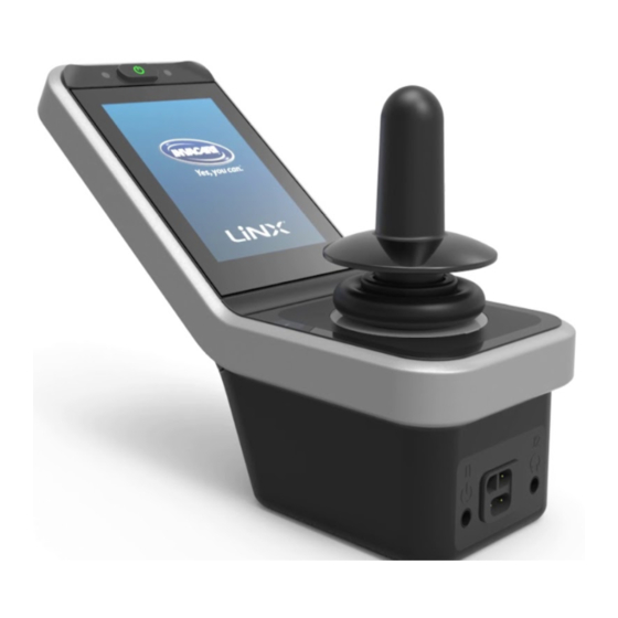
LiNX® Control System 1.4.1 Intended Use — REM400 The LiNX REM400 is a Remote of the LiNX family, intended to allow powered wheelchair users to interact with the LiNX System. The REM400 Remote allows control of drive, actuator, lighting and connectivity functions. It provides an input for battery charging and contains a Bluetooth interface for connectivity functions only (HID and diagnostics). -
Page 7: Safety
Invacare for repair. WARNING! WARNING! Risk of Death, Injury or Damage... - Page 8 – Performance adjustments should only be made approved Invacare accessories. Unapproved by professionals of the healthcare field or accessories have not been tested by Invacare persons fully conversant with this process and and are not recommended for use with the driver's capabilities.
- Page 9 Safety WARNING! DANGER! Risk of Injury or Damage Risk of Death, Serious Injury, or Damage Connector pins on cables connected to the power Lighted cigarettes dropped onto an upholstered module can still be live even when the system is seating system can cause a fire resulting in death, off.
-
Page 10: Live Edit Guidelines
– Do not open or disassemble any case. – Users should use caution when driving the wheelchair while operating in Live Edit mode. As a manufacturer of wheelchairs, Invacare – Users should use care to stay in the endeavors to supply a wide variety of wheelchairs to programming range. -
Page 11: Usage Guidelines
Safety 2.1.2 Usage Guidelines WARNING! Risk of Injury, Damage or Death DANGER! Use of the wheelchair while judgement or ability Risk of Death, Serious Injury, or Damage is impaired may result in injury, damage or death. Misuse of the wheelchair may cause component –... -
Page 12: Setup And Service Guidelines
(service) parts may cause death, serious injury, ALWAYS have assured cleared distance with all or damage. objects in environment. – Replacement parts MUST match original Invacare parts. CAUTION! – ALWAYS provide the wheelchair serial number Risk of Injury to assist in ordering the correct replacement Remote module can get hot when exposed to parts. - Page 13 Safety WARNING! Risk of Death, Serious Injury, or Damage Improperly connected joystick could cause loss of power resulting in death, serious injury, or damage. – Ensure the joystick is securely connected to controller. CAUTION! Risk of Damage Operating the wheelchair in rain or dampness may cause the wheelchair to malfunction electrically and mechanically;...
-
Page 14: Electromagnetic Compatibility (Emc) Information
LiNX® Control System 3 Electromagnetic Compatibility (EMC) Information 3.1 Electromagnetic Compatibility Refer to the power wheelchair base and seating system user manuals for more electromagnetic compatibility information for your mobility device. Dynamic Controls Electronic Controllers have been tested on typical, representative vehicles to confirm compliance with the following appropriate EMC standards: •... -
Page 15: Components
Components 4 Components E Bus socket F Stereo jack sockets 4.1 User interface REM400 G Infrared transmitter H Speaker I Charger socket J Toggle switches 4.2 Screen composition overview A Battery bar A Multipurpose buttons B Status bar B ON/OFF button/Status LED C User function screen C Touch display D Navigation button... -
Page 16: Battery Bar
LiNX® Control System 4.2.1 Battery bar Time The battery bar provides a graphical display of the battery’s The time is displayed as a 12– or 24–hour clock. It is set current state of charge and, when a battery charger is using the coordinated universal time (UTC) and an offset connected, the charging status. -
Page 17: User Function Screen Overview
Components This notifies you that a fault occurred. Left-handed Right-handed The number indicates the type of fault. Refer to 8.1.1 Fault codes and diagnosis codes, page 113 for more information about fault codes. This notifies you that a seating lock-out is active. - Page 18 LiNX® Control System Drive screen Meaning Indicator REM400 REM500 REM2xx CREM CREM-LF Head Array Drive screens can be pre-set with different maximum speeds to fit your needs and your environment. For example a drive screen with pre-set lower maximum speed can be used Sip and Puff for indoors and a drive screen with pre-set total maximum speed for outdoors.
- Page 19 Components Connectivity screen no symbol No Gyro is connected to the system or enabled for drive function. Gyro disabled. Gyro enabled. Seating screen Connectivity screens allow you to communicate with external devices. The connectivity function included on your remote is a mouse mover. The mouse mover allows you to control the cursor on a PC or laptop’s screen with a user input on the wheelchair, such as the joystick on the remote module or buttons connected via control inputs.
- Page 20 LiNX® Control System Utility Screen • A Short press / Momentary press, • B Long press. Fig. 4-3 Fig. 4-1 Example of a Fig. 4-2 Example of a By default, this function is only enabled for chair three-quadrant (3Q) navigation four-quadrant (4Q) navigation configurations with an external control input that will not utility screen...
-
Page 21: Navigation Button
Components Arrangement When activated, the navigation button changes its color from grey to blue. Function screens The navigation button has two important functions: 1. A visual indication of the configured interaction mode. Configured for swipe-and-tap actions This means, that swiping and tapping the screen Pro- activates different functions. -
Page 22: Labels On The Product
LiNX® Control System 4.4 Labels on the Product Product label containing: Labels on Dynamic Controls’ Parts 1. Part number 2. Dynamic Controls logo Labels of Dynamic Controls’ parts are located on rear side of 3. Dynamic Controls’ part the part. Depending on the part not all labels are available. description 4. - Page 23 Components Tamper evident seal. Recommendation to read the instruction manual before using the module. READ INSTALLATION This is the WEEE symbol MANUAL BEFORE USE (Waste Electrical and Electronic Equipment Product label containing: Directive). • Dynamic Controls' This product has been website address supplied from an •...
- Page 24 LiNX® Control System Labels on Toggle Switches Labels on Adaptive Switch Labs’ Parts Labels of Adaptive Switch Labs’ parts are located on either on left rear side of the part (head arrays) or the interface box. Depending on the used part not all labels are available. Product label (head array) containing: •...
-
Page 25: Setup
Setup 5 Setup 5.1 Connecting the remote CAUTION! Risk of unintended stops If the plug of the remote cable is broken, the remote cable may come loose while driving. The remote could suddenly switch off when losing power. This results in an unintended stop. –... -
Page 26: Usage
LiNX® Control System 6 Usage Powering down the remote 1. Press ON/OFF key A. 6.1 Operating the remote Powering up the remote Press ON/OFF key A. Shut down screen is displayed. After a few seconds the remote is powered down. Attendant in charge Start screen lights up. -
Page 27: Controls On Menu Screen
Usage Also the status LED inside the ON/OFF button of the primary remote is turned off. 1. Press ON/OFF button of primary remote to take over Fig. 6-1 Example of a button control. 1. Tap on button A to perform the action. Attendant control powers down automatically. - Page 28 LiNX® Control System Menu Screen Fig. 6-5 Fig. 6-4 Entry Function Entry Function A Display Open display settings A Clock View and edit time. B Interaction Open interaction settings B Screen Lock Activate screen lock. C Connectivity Open connectivity settings C Glove Mode Activate Glove Mode.
- Page 29 Usage Interaction Entry Function A Tap-Only Mode Toggle between tap mode and swipe-and-tap mode B Tap Zone Defines the area used for detecting a tap action on touch screen. It sets the area around the point of initial contact, within a tap is Fig.
-
Page 30: Configuring Menu Screen
LiNX® Control System Closing Menu Screen Entry Function C Left Hand Toggle between right-hand and Mode left-hand usage of remote. When the switch is set to ON, all user controls (navigation button, speed slider, lighting controls etc) are displayed and operable from the left-hand side of the screen. -
Page 31: Locking Screen To Avoid Unintentional Response
Usage Fig. 6-14 Fig. 6-11 Tap on button D to return to Menu screen. If necessary, tab switch C to toggle between 12– and 6.1.4 Locking Screen to Avoid Unintentional Response 24–hour clock. The screen lock is a security feature that the user can activate to prevent other people accidentally or intentionally interfering with the touch screen. -
Page 32: Navigating Through User Function Screens
LiNX® Control System Turn remote off and on (power-cycle) to deactivate screen lock. Keep the touch screen dry to ensure proper response during use. 6.2 Navigating through user function screens How to navigate through user function screens depends on how the navigation button is configured. Refer to 4.3 Navigation button, page 21, for more information about Fig. -
Page 33: Using Direct Navigation
Usage Swipe over screen or tap navigation button to open screen preview display. Swipe left or right to change function screens. 3. Tap on selected function screen, tap navigation button or wait for a few seconds to activate selected function Fig. - Page 34 LiNX® Control System Changing profiles Profile 4 Profile 1 Swipe up or down to activate another profile. The screen view focuses on the first function screen or the last-used function screen in the profile, depending on how the programming is set up. 2.
-
Page 35: Using Indirect Navigation
Usage The screen view focuses on the first function screen or 1. Short press to change function screen. the last-used function screen in the profile depending 2. Long press to change profile. on how the programming is set up. No screen preview is displayed. The function screens change 2. -
Page 36: Menu Select
LiNX® Control System 6.2.4 Menu select automatically after a period of time without user activity. This period can be set by your provider. With menu select, you perform both, the navigation and the function screen selection. There are two different ways, the indirect navigation is entered: Function screen menu Profile menu... - Page 37 Usage Menu select with 4Q operation 1. Press external switch. Profile menu opens. Give right input D to select profile. Function screen menu opens. Give forward input A or reverse input B to switch between function screens. Give left input C to switch back to previous menu. Give forward input A or reverse input B to switch between profiles.
- Page 38 LiNX® Control System 6. To go back to profile menu, give right input until Back button D is selected. Give left input to go back to profile menu. Give left input C to select function screen. Give right input A to change profile. 4.
-
Page 39: Overview Scan Select
Usage 6.2.5 Overview scan select Profiles Function screens Selected function screen Navigation Entry Navigation Entry First Profile Active User Function Select function No selection screen One iteration Select function Select profile screen No selection Select No function screen selected Timer 6.2.6 Scan select or ignore it. - Page 40 LiNX® Control System you must provide a select command. The profile menu is Function screen menu Profile menu always entered when exiting the idle state. Navigation entry By default the indirect navigation is started via an external switch, for example, an egg switch. If Stand by select is enabled by your provider, the indirect navigation starts automatically after a period of time without user activity.
- Page 41 Usage • If Navigation entry is set to Active User Function, the Scan select with 4Q or 3Q operation currently selected function screen item is displayed on User input type Mapping for scan select the touch screen. If this function screen is not selected, the system iterates once through the remaining function Left input: select screen items in the profile, wrapping around from the...
-
Page 42: Using The Multipurpose Buttons
LiNX® Control System 6.4 Using the Toggle Switches (Optional) process. The duration of time before the next item is displayed, is shown by an indicator ring. 1. Give select input, if control navigation item A is displayed. 6.3 Using the multipurpose buttons Fig. -
Page 43: Proportional Driving Mode
Usage By default, the following actions are performed: Left toggle Forward command Power button switch (On / Off) Backwards switch to next command (short function card press) Backwards Switch to next command (long profile press) Right toggle Forward command Increase speed switch by 10 % The speed of the wheelchair is proportional to the joystick... -
Page 44: Controlling The Maximum Speed
LiNX® Control System The joystick can also be used to wake up the system when In each drive screen you are able to control the pre-set in sleep mode, if this parameter has been enabled by the maximum speed depending on your needs. provider. -
Page 45: Latched Driving Mode
– the Latch Drive Timeout has expired. button disappear from the display. The current speed is displayed by a green ring around the speedometer. To avoid potentially dangerous situations Invacare recommends to make yourself familiar with the 6.6 Latched driving mode... -
Page 46: External Stop Switch
LiNX® Control System 5 Step Up/Down Cruise Control The Latch Drive Timeout period is restarted whenever a subsequent drive command is given. Each drive function can be assigned with a latched driving The Latch Drive Timeout is set by the provider. To mode by your provider. -
Page 47: Step Up
Usage External stop switch test 6.6.2 1 Step Up The external stop switch test checks that the external stop switch is functioning correctly. The test is conducted once per power cycle when: • the wheelchair is powered up in a latched drive mode function or •... -
Page 48: Step Up
LiNX® Control System • Perform emergency stop Stopping Let Latch Drive Timeout expire. Use one of the following methods to stop: 6.6.3 3 Step Up • Give drive command in opposite direction (a reverse command when driving forward or a forward command when driving in reverse). -
Page 49: Step Up/Down
Usage Driving 6.6.5 3 Step Up/Down 1. Give drive command in desired direction (forward or reverse). 2. Release drive command. Wheelchair speed accelerates to 20% of the maximum drive speed. 3. Give forward command when driving forward or reverse command when driving in reverse to accelerate to next fixed speed. -
Page 50: Step Up/Down
LiNX® Control System 3. Give forward command when driving forward or reverse In this mode, you can step up or down through one of five command when driving in reverse to accelerate to next fixed speeds. The speeds available are 20%, 40%, 60%, 80% fixed higher speed. -
Page 51: Cruise Control
Usage • Perform emergency stop 5. Give drive command in opposite direction (reverse when • Let Latch Drive Timeout expire driving forward or forward when driving in reverse) to decelerate speed. 6.6.7 Cruise Control 6. Release drive command. New speed is held constantly. Stopping Use one of the following methods to stop: •... -
Page 52: Operating The Position Lights
LiNX® Control System 6.8 Operating the position lights If you drive outside, turn on the position lights under bad visibility conditions or darkness. To operate the position lights, you need to stop the mobility device. Turn on position lights Fig. 6-21 Lighting button panel overlays screen. -
Page 53: Operating The Hazard Lights
Usage 6.9 Operating the hazard lights Turn off position lights To operate the hazard lights, you need to stop the mobility device. Turn on hazard lights Fig. 6-23 Tap Lighting control button A. Fig. 6-25 Tap Lighting control button A. Fig. - Page 54 LiNX® Control System Tap Hazard lights symbol B to turn the hazard lights on. Turn off hazard lights Fig. 6-27 Hazard lights icon becomes illuminated in the lighting Fig. 6-28 dashboard. Tap Lighting control button A. 3. Tap button C to close Lighting button panel. If you start driving, the Lighting button panel overlay disappears automatically and the hazard lights remain turned on.
-
Page 55: Operating The Turn Signals
Usage 6.10 Operating the turn signals Tap left turn signal symbol B or right turn signal symbol C to turn the turn signal on. To operate the turn signals, you need to stop the mobility device. Turn on turn signals Fig. -
Page 56: Operating The Horn
LiNX® Control System 6.11 Operating the horn Turn off turn signals 1. Tap horn button A to sound horn. Fig. 6-33 Tap Lighting control button A. Horn sounds as long as button is tapped. 6.12 Operating Lighting Functions and Horn via Utility Function Card Via a utility function card you are able to operate the lighting functions and horn with an external input. -
Page 57: Locking/Unlocking The Remote
Usage Locking the remote Fig. 6-35 • Give forward demand A to sound horn. Press ON/OFF button for more than three seconds, until • Give short demand to right B to turn on/off position a locking overlay is displayed. lights. 2. -
Page 58: The Sleep Mode
LiNX® Control System 6.15.1 Through seating screens If you do not apply the unlock sequence or the ON/OFF button is pressed again before the unlock sequence is complete, the system returns to the locked state and powers down. 6.14 The sleep mode The sleep mode is not set at the factory, but can be enabled by your provider. - Page 59 Usage Choose the seating screen with the seating function you Displayed symbols and their meanings want to operate, refer to chapter 6.2 Navigating through user function screens, page 32. Powered seat tilt Powered recline Seat lifter Give forward or reverse command to operate seating function.
- Page 60 LiNX® Control System Other configurations • Latched configuration A latched configuration allows you to operate a motion The displayed function screens are configuration without continuously providing a command. examples only. A latched configuration can be a single powered seating function or a four quadrant configuration. •...
-
Page 61: Through External Switches
Usage Powered recline Elevating seat Left or center-mount powered elevating legrest In a four quadrant configuration it is possible to mix the motion operations, like displayed in the example. Right powered elevating legrest 6.15.2 Through external switches Not all configurations and combinations of powered Both powered elevating legrests seating functions through external switches are available on all products. - Page 62 LiNX® Control System • Powered seat tilt only • Center-mount elevating legrest (LNX) only 1. Make sure mobility device is on level surface and turned 2. Deflect and hold toggle switch up A or down B to move particular seating function. Seating function moves as long as toggle switch is 1.
- Page 63 Usage 4–way toggle switch Powered seat tilt and LNX legrest Powered seat tilt up A (Forward) B (Reverse) Powered seat tilt down LNX up C (Left) LNX down D (Right) Powered recline and LNX legrest A (Forward) Powered recline and LNX up Powered recline and LNX down B (Reverse) 1.
- Page 64 LiNX® Control System 4–way button switch Powered seat tilt and LNX legrest A Powered seat tilt up B Powered seat tilt down C LNX up D LNX down Powered recline and LNX legrest A Powered recline and LNX up B Powered recline and LNX down 1.
- Page 65 The 10-Way Switch can be customized to operate other functions than those Elevating seat down Right powered elevating that are shown. Contact an Invacare provider to legrest down customize the 10-Way Switch. Powered recline down + Powered seat tilt up Powered legs up 1.
-
Page 66: Speed Reduction And Seating Function Inhibits
• Tilt limit The mentioned speed reduction and seating function limits do not apply to all Invacare wheelchair models. Speed reduction If the elevating seat has been adjusted above a certain point, the drive electronics considerably reduces the speed of the wheelchair. -
Page 67: Connectivity Screens
Usage • Elevating seat lockout functions are disabled. Contact your provider to activate Connectivity Screens. The mouse mover function allows you to control the cursor on a PC or laptop’s screen with a user input on the wheelchair, such as the joystick on the remote module or external joysticks. - Page 68 LiNX® Control System Fig. 6-40 Settings menu opens. Open Connectivity settings C. Fig. 6-38 Long press navigation button A. Fig. 6-39 Status display opens. Open Settings menu B. Fig. 6-41 Connectivity settings menu opens. This menu is split into two sections: 60101834-C...
- Page 69 Usage Pairing PC or Laptop with LiNX system D Functions Perform this operation promptly to the Pairing E Paired devices process on your remote (see Pairing the LiNX system 5. Tap on Pair New Device button F at bottom of menu. with a user’s device, page 67).
- Page 70 LiNX® Control System Fig. 6-44 Fig. 6-45 All available devices are displayed. Locate LiNX Fig. 6-46 device name that as displayed on the touch screen (REM-J16130951) and select it. Wait for device to connect. Click on Next button. Click on Next as soon as device is connected. Fig.
- Page 71 Usage Linking connectivity card with user’s device Connectivity cards must be linked to a paired device. To link a connectivity card to a device, open the connectivity settings menu. Fig. 6-48 If the device paired successfully, a confirmation screen is displayed on the remote module.
- Page 72 LiNX® Control System 6. If you uses Mouse mover function card, cursor speed settings are displayed on top. Scroll down to section Function Uses Device. Fig. 6-52 Settings menu opens. Open Connectivity settings C. Fig. 6-54 Tap on Not Linked button D. Fig.
- Page 73 Usage Connecting devices with LiNX system Removing paired devices To connect to a device, select the appropriate connectivity card from a profile. If the connectivity function has been paired to a device and the device has been linked to the function, then it attempts to connect to the device via Bluetooth.
- Page 74 LiNX® Control System Fig. 6-57 Settings menu opens. Open Connectivity settings C. Fig. 6-59 Check details on following screen and tap Forget this Device button. Fig. 6-58 Select paired device in section Paired Devices, e. g. Laptop D. Fig. 6-60 Tap on Forget this Device button again or Cancel button, to cancel removing.
-
Page 75: Mouse Mover
Usage Selecting a connectivity card 6.16.2 Mouse Mover For more information about selecting user function cards, see 6.2.2 Using direct navigation, page 33 or 6.2.3 Using indirect navigation, page 35. Fig. 6-62 A Connectivity screen name B Mouse move indicator Fig. - Page 76 LiNX® Control System Connectivity The name can be used Scroll indicator The scroll indicator screen name to uniquely identify this changes from grey screen’s purpose. to blue when active. That is, when the user Mouse move The mouse move input is controlling indicator indicator changes from the connected device’s...
- Page 77 Usage The set-up procedure can be performed in any order, but involves the following: • Selecting a connectivity screen, • pairing the LiNX system with a user’s device • linking the connectivity screen with the user’s device • configuring the mouse mover function (cursor speed). Configuring the mouse mover function (cursor speed) The cursor speed settings can be found in the connectivity function’s menu.
- Page 78 LiNX® Control System Fig. 6-65 Settings menu opens. Open Connectivity settings C. Fig. 6-67 Mouser mover — Cursor settings For each mouse mover function the following cursor settings can be set: • Fast Cursor Speed • Slow Cursor Speed • Slow Movement Time Fig.
- Page 79 Usage Operating the Mouse Mover A X-axis: time The following operation description assumes that a B Y-axis: speed connectivity screen with a mouse mover function has been C Slow Cursor Speed set up as described in Setting up a Mouse Mover, page 76. D Ramp Moving the cursor E Fast Cursor Speed...
-
Page 80: Switch Control
LiNX® Control System Scrolling A Connectivity screen name The scroll mode button is an external button, such as an B Bluetooth connection status egg switch or buddy button. C Switch control indication 1. Press and hold scroll mode button. 2. Use assigned user input or programmed control inputs Connectivity The name can be used to perform up and down scroll actions. -
Page 81: Setting Up Switch Control
Usage 6.17.2 Setting up switch control information look into your user manual or at Android Accessibility Help pages. The following set up procedure assumes that a switch control connectivity screen is available and selectable in one or more profiles. It also assumes that the user's device (iOS or Android) to which the LiNX system connects to, has an active Bluetooth connection. - Page 82 LiNX® Control System Fig. 6-73 Open Assign Keys for Scanning (Assign Keys for Scanning) menu or Assign Keys to Actions (Assign Keys to Actions) menu. Android placed functions in two different menus. Fig. 6-74 Select the function you like to control from the list, such as Select (Select).
- Page 83 Usage Fig. 6-76 Activate Switch Control. Fig. 6-75 Activate the external switch, for example tap on Touch screen or deflect joystick to the left. 6. Click on button Save (Save). 7. If required, repeat the steps to add more switches. Fig.
- Page 84 LiNX® Control System Configuring Switch Control (iOS) Fig. 6-80 Tap on menu entry Add new Switch (Add New Switch). Fig. 6-78 Settings > General > Accessibility Open the switch control menu on your mobile device. Fig. 6-81 Tap on button External (External). You are prompted to activate the external switch.
-
Page 85: Operating Switch Control
Usage Fig. 6-84 Assign an action to switch. From the Actions (Actions) menu choose a switch action, such as Select Item. 8. If required, repeat the steps to add more switches. Fig. 6-82 Activate external switch, for example tap on Touch screen or deflect joystick to the left. -
Page 86: Using Secondary Inputs
LiNX® Control System set up as described in 6.17.2 Setting up switch control, page quadrants (3Q), such as a Head Array or a Four Switch Proximity Array. There you have the possibility to move forward, right or left with the aid of proximity sensors. In Controlling Mobile Device order to allow the wheelchair to be driven in reverse or 1. -
Page 87: Using The Extremity Control Joystick
Usage Changing function screens All components mentioned below describe the usage of the default set-up. For individual set-up, contact By default an egg switch, used for function or profile your provider. changes, is mounted to the headrest. For difference between function screen and profile, 6.18.1 Using the Extremity Control Joystick (Chin control) refer to chapter 4.2.3 User function screen overview, Powered adjustable... -
Page 88: Control)
LiNX® Control System 4. Give short input to left C to turn on/off hazard lights. Moving Chin Control 5. Give long input to left or right D to turn on/off left 1. Loosen wing bolt B to adjust joystick. or right turn signal. Activate a drive function screen to drive normally, while position lights and hazard lights remain turned After more than ten seconds, the turn signals turn... -
Page 89: Using The Compact Single Switch Joystick
Usage 6.18.3 Using the Compact Single Switch Joystick Driving Activate utility function screen. Deflect joystick from neutral position to drive in desired 2. Give input to front A to turn on horn. direction. 3. Give short input to right B to turn on/off position lights. 4. -
Page 90: Using The Micro Extremity Control Joystick
LiNX® Control System 1. Short press joystick button A to change function screen. After more than ten seconds, the turn signals turn 2. Long press joystick button A to change profile. off automatically. For operating the powered seating functions, refer to 6.15.1 6.18.4 Using the Micro Extremity Control joystick Through seating screens, page 58. -
Page 91: Using The Pediatric Compact Joystick
Usage 3. Give short input to right B to turn on/off position lights. 4. Give short input to left C to turn on/off hazard lights. 5. Give long input to left or right D to turn on/off left or right turn signal. Activate a drive function screen to drive normally, while position lights and hazard lights remain turned After more than ten seconds, the turn signals turn... - Page 92 LiNX® Control System For difference between function screen and profile, Activate a drive function screen to drive normally, refer to chapter 4.2.3 User function screen overview, while position lights and hazard lights remain turned page 17. For operating the powered seating functions, refer to 6.15.1 After more than ten seconds, the turn signals turn Through seating screens, page 58.
-
Page 93: Using The Sip And Puff
Usage 6.18.6 Using the Sip and Puff Contact your Invacare provider for more information about maintaining and troubleshooting the Sip and WARNING! Puff system. Risk of Injury or Damage Improper mounting or maintenance of the Sip For further maintenance and cleaning instructions, see 7 Maintenance, page 109 . - Page 94 LiNX® Control System 3. When in latched driving mode, puff soft into mouthpiece to veer to the right. 4. When in latched driving mode, sip soft at mouthpiece to veer to the left. For more information about the calibration of hard and soft inputs, refer to the service manual of the LiNX system.
-
Page 95: Using The Sip And Puff Head Array
Usage 6.18.7 Using the Sip and Puff Head Array WARNING! Risk of Injury or Damage WARNING! Improper mounting or maintenance of the Sip Risk of serious injury and Puff control including the mouthpiece and Proximity sensors are sensitive to water. If breath tube may cause injury or damage. - Page 96 LiNX® Control System Driving Contact your Invacare provider for more information about maintaining and troubleshooting the Sip and This component combines simple sip and puff controls with Puff system. head movements. Right and left turns are controlled by sensors located in the pads of the Head Array.
- Page 97 Usage must stay inside your mouth. As soon as the lipswitch is pressed while driving, the wheelchair stops. Changing function screens The lipswitch can also be used as a mode function switch. For difference between function screen and profile, refer to chapter 4.2.3 User function screen overview, page 17.
-
Page 98: Using The Head Array
LiNX® Control System 6.18.8 Using the Head Array If the head comes within 6 mm of a sensor, the sensor is activated and the wheelchair starts driving. WARNING! By default, the Head Array powers up as soon as the Risk of serious injury wheelchair is powered up and powers down as soon as the Proximity sensors are sensitive to water. - Page 99 Usage 3. Change back to forward drive function screen. Reverse active Forward active Activate center pad A and right pad B at the same time to veer to the right. 4. Activate center pad A and left pad C at the same time to veer to the left.
- Page 100 LiNX® Control System Activate utility function screen. Seating functions can only be operated with the right 2. Give input to front A to turn on horn. or left pad of the head array. 3. Give short input to right B to turn on/off position lights. Operating the lighting functions and horn 4.
-
Page 101: Using The Four Switch Proximity Array
Usage 6.18.9 Using the Four Switch Proximity Array WARNING! Risk of serious injury Proximity sensors are sensitive to water. If enough water is present close to sensors, they 1. Cover sensor B to drive forward. may be activated and mobility device may start 2. -
Page 102: Using The Wireless Mouse Emulator
LiNX® Control System Reverse active Forward active Activate utility function screen. 2. Give input to front A to turn on horn. 3. Give short input to right B to turn on/off position lights. 4. Give short input to left C to turn on/off hazard lights. To revolve, you only need to cover sensors A or C. - Page 103 Usage 3. Mouse emulator and Head Array connect automatically. Dip switch 5 & 6: Cursor delay 4. Default set up is: • Back pad: Mouse moves up and down • Right pad: Mouse moves left and right • Left pad: select disabled 1.0 sec 2.0 sec...
- Page 104 LiNX® Control System Dip switch 11 & 12: Cursor movement options E This setting controls the amount of time the Left and Right Click switch must be held before it will latch. Once the latch is no longer required, press the Right Click or Left Click switch for the same length of time to deactivate the latch.
-
Page 105: Disabling Bluetooth
Usage 6.19 Disabling Bluetooth Mouse action Number The embedded Bluetooth functionality can be disabled when No change powering up the system. Down 1. Press and hold the ON/OFF button for more than three Left seconds. Right Right click The disabled Bluetooth functionality is indicated by an icon in the status bar and the status LED inside the ON/OFF Left click button pulsing for a duration of six seconds. -
Page 106: Battery Alarms
LiNX® Control System While charging, the wheelchair is in drive inhibit mode. For more information about the drive inhibit mode, refer to 8.3 Drive inhibit indication, page 115 . NEW Batteries Only—The wheelchair power must be on during charging to ensure that accurate battery charge levels display on the remote. -
Page 107: Using The Usb Charger
Usage Risk of property damage Over voltage Handle USB charger with care, otherwise damage could occur. This is displayed if the batteries are overcharged. – Always keep the USB charger dry. If USB Disconnect the battery charger immediately. charger gets wet, let USB charger dry before Low voltage use. - Page 108 LiNX® Control System Open bung A. 2. Connect device with USB port. Replace bung when USB ports are not in use. The usage of the USB charger influences the drive range of the mobility device. For more information about the drive range, refer to chapter Technical Data in the user manual of your mobility device.
-
Page 109: Maintenance
Where any doubt exists, consult your nearest Invacare reserves the right to ask for any item back that has Invacare provider. an alleged defect in workmanship. Refer to the Warranty section in this manual for specific warranty information. -
Page 110: User/Attendant Inspection Checklists
Seating Seat Cushion Covers, Back Cushion components, such as connectors, terminals or cables. Foam, Back Cushion Covers, Contact your Invacare provider to replace damaged Headrest Foam, Headrest Covers, components. Footplate Covers, Calf Pad (if Ensure that all connectors are fully mated. -
Page 111: Six Month Inspection
Maintenance technician. Actual items to be inspected during the service CAUTION! inspection may vary according to the specific wheelchair: Risk of Damage Cleaning or maintenance may cause damage to 7.5.1 Six Month Inspection carpeting or flooring. – Place the wheelchair in a well ventilated Cables shall be inspected periodically to ensure area where cleaning or maintenance can be that they are routed and secured properly. - Page 112 LiNX® Control System 1. Use a cloth dampened with warm water and mild non-abrasive soap to clean this product. 2. Dry the surface with dry cloth. 3. DO NOT use solvents or kitchen cleaners. 60101834-C...
-
Page 113: Troubleshooting
Troubleshooting 8 Troubleshooting The table below describes the fault indication and a few possible actions that can be taken to rectify the problem. The actions listed are not in any particular order and 8.1 Fault diagnosis are suggestions only. The intention is that one of the If the electronic system shows a fault, use the following suggestions may help you clear the problem. -
Page 114: Oon ("Out Of Neutral")
LiNX® Control System Drive OON warning Fault Fault Possible action icon description Right • Check cables and connectors. magnetic • Check right motor (or motor brake fault lock lever) is engaged. • Refer to the chapter “Pushing the mobility device in freewheel mode”... -
Page 115: Drive Inhibit Indication
Troubleshooting Seating OON warning Drive inhibit mode is indicated by the screen shown. When a system is powering up or after a function change, no direct access switches can be active, otherwise a seating OON warning is displayed. During a seating OON warning, the OON overlay is displayed and the seating motions do not operate. -
Page 116: Technical Data
LiNX® Control System 9 Technical Data 9.1 Technical specifications Mechanical specifications Permissible operating, storage and humidity conditions Temperature range for operation according to ISO 7176-9: • -13 °F (-25 °C)–122 °F (+50 °C) Recommended storage temperature: • 59 °F (15 °C) Temperature range for storage according to ISO 7176-9: •... -
Page 117: Wireless Technology
Wireless Technology 10 Wireless Technology Technical Classic Bluetooth Smart (low Specification energy) Bluetooth 10.1 Wireless Technology Overview Security 128-bit AES with 56/128-bit and The LiNX control system makes use of Bluetooth wireless Counter Mode application layer technology. Bluetooth is a wireless communications system user defined CBCMAC and that is designed to operate in short-range wireless personal... -
Page 118: Linx Wireless Functions
LiNX® Control System homes, vocational settings and health care facilities. Across • The state of charge of the battery, these environments, there are numerous different items of • Active and historical fault data, both medical and non-medical equipment that also operate •... -
Page 119: Quality Of Service
Wireless Technology Whilst the wheelchair may be in motion when the system 10.4.1 Data Integrity is being configured, instructions for safe use, training and Errors in the integrity of the data transmitted are a nuisance built-in safety mechanisms minimize the potential for and will not cause a safety related issue. -
Page 120: Wireless Coexistence
LiNX® Control System 10.6 Cybersecurity Bluetooth connections, inherent encryption of the Bluetooth protocols, and direct indication to a user when a connection The LiNX product range has been designed with cybersecurity is made. in mind to assure device functionality and safety. The Due to the nature of the functions using the wireless cybersecurity measures taken address: technology, there is no requirement for redundancy. -
Page 121: User Actions
Wireless Technology • The system will only run valid software. Cyclic Redundancy Checks (CRC) are conducted on the software before it is executed. • LiNX products use Class 2 Bluetooth wireless technology. This technology has built-in safety features that can maximize the product's integrity. -
Page 122: Warranty
Invacare ships the product to the original a period of one (1) year from the date Invacare ships the purchaser or provider: bearings and bushings, upholstered product to the original purchaser or provider: base frame,... -
Page 123: Limitations And Exclusions
Warranty 11.5 Disclaimers nature of the defect and, if the product is serialized, indicate the serial number. Do not return products to Invacare The Warranty may not be modified or waived in any manner without Invacare’s prior written authorization. whatsoever without Invacare's express written authorization.