Advertisement
Quick Links
Advertisement

Related Manuals for Invacare G91S


Summary of Contents for Invacare G91S
- Page 1 Yes, You Can.® ® Invacare G91S The remote User manual...
- Page 2 How can you get in touch with Invacare®? If you have any questions or need support, please contact your authorised Invacare® Dealer, who has the necessary know-how and equipment plus the special knowledge concerning your Invacare® product, and can offer you all-round satisfactory service. Should you wish to contact Invacare® directly, you can reach us in Europe at the following addresses and phone numbers.
- Page 3 +44 (0)1656 77 62 20 Pencoed uk@invacare.com Bridgend CF35 5AQ WWW: www.invacare.co.uk United Kingdom Invacare Mecc San s.r.l. +39 0445 38 00 59 Via dei Pini, 62 Fax: +39 0445 38 00 34 I - 36016 Thiene (VI) italia@invacare.com ITALIA WWW: www.invacare.it...
- Page 4 +46 (0)8 761 81 08 Fagerstagatan 9 sweden@invacare.com S-163 91 Spånga finland@invacare.com Sverige WWW: www.invacare.se Tillverkare: MÖLNDAL Invacare® Deutschland GmbH : +46 (0)31 86 36 00 Kleiststraße 49 Fax: +46 (0)31 86 36 06 D-32457 Porta Westfalica ginvacare@invacare.com Deutschland LANDSKRONA ...
- Page 5 Keypad..........................10 3.1.2 Displays ...........................11 Bottom side .........................12 Using buddy buttons with the remote .................13 Functions ..................14 General information ......................14 Connecting the G91S remote .....................15 Joystick ..........................16 Switching on the remote .....................21 Displaying status information....................22 4.5.1 System status ........................22 4.5.2 Battery charge display .....................22 Driving..........................23...
- Page 6 4.8.1 Activating light mode......................28 4.8.2 Selecting and actuating light options ................29 Adjust seat electrically ......................30 4.9.1 Activating adjust mode.....................30 4.9.2 Selecting and actuating adjustment options ..............31 4.10 Controlling the ECU ......................32 4.10.1 Activating ECU mode.....................33 4.10.2 Controlling the ECU module ..................34 4.11 Using the chin control with the remote ................35 4.12...
- Page 7 The decision whether the model is suitable for you as the user may only be taken by medical specialists with appropriate aptitude. Invacare® or their statutory representatives can accept no liability in cases in which the remote has not been adapted to suit the user's handicaps.
- Page 8 CAUTION: any changes to the drive program can affect the driving characteristics and the tipping stability of the mobility device! • Changes to the drive program may only be carried out by trained Invacare® specialist dealers! • Invacare® supplies all mobility devices with a standard drive program ex-works. Invacare®...
- Page 9 Presentation of remote The G91S remote is a control element for use on an electrically operated mobility device. It is operated with a joystick as standard. Up to 3 buddy buttons can optionally be used for the controller and for switching functions in addition to the joystick.
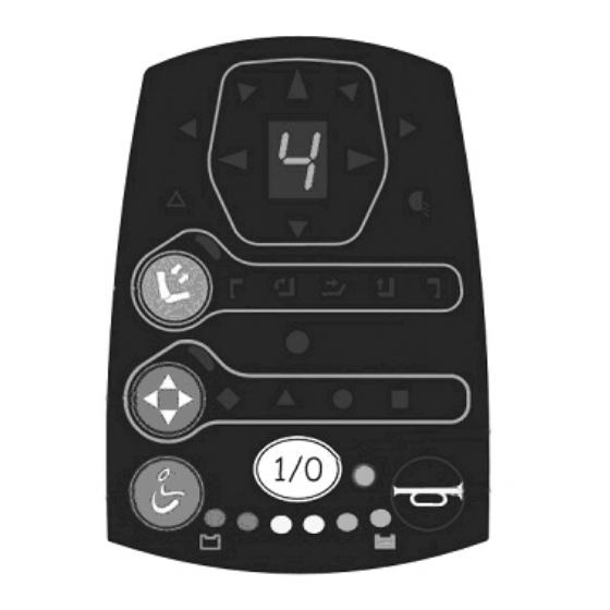
- Page 10 Displays and controls Top side 3.1.1 Keypad 1) Adjust mode (electrical adjustment options, light) 2) ECU mode (ECU mode 1 and 2) 3) Drive mode 4) ON/OFF 5) Horn...
- Page 11 3.1.2 Displays 1) Warning blinker 2) Left-hand direction indicator 3) 7-segment display 4) Right-hand direction indicator 5) Lighting 6) Status 7) Battery charge display...
- Page 12 Bottom side 1. Socket for buddy button 1 (corresponds to "Drive mode" button) 2. Socket for buddy button 2 (corresponds to "ON/OFF" button) 3. Socket for buddy button 3 for additional modes 4. Socket for bus cable...
- Page 13 Using buddy buttons with the remote What is a buddy button? A buddy button () is an additional button which can be used to activate remote functions. The sockets for buddy buttons are located on the underside of the remote. You can connect up to 3 buddy buttons.
- Page 14 Scanning mode must be adjusted by your Invacare® dealer. NOTE: Your Invacare® dealer can activate or deactivate the various options to adapt them precisely to your requirements. If you use buddy buttons you can activate the options so that you can run...
- Page 15 The remote is compatible with mobility devices using ACS systems (ACS 1 and 2), since specific connections must be available. Please contact your Invacare® dealer for more information. Connecting the G91S remote Note: Installation and software programming may only be carried out by your Invacare® dealer.
- Page 16 Joystick NOTE: The joystick functioning principle also applies to the following controllers: • chin control • four-button controller • five-button controller • head control NOTE: The joystick can only be used together with a main remote. The joystick function depends on the operating mode selected.
- Page 17 • In drive mode, you can move the mobility device variably in any required direction and regulate the speed using the joystick.
- Page 18 • In adjust mode you can change the adjustment options (1) using the joystick and adjust the seat components (2). • You can control the ECU channels in ECU mode. ECU mode 1:...
- Page 19 ECU mode 2: • You select the light options in light mode.
- Page 20 • If you have selected the horn using the buddy button, use the joystick to sound the horn.
- Page 21 Switching on the remote NOTE: You will require an input device such as (typically) a joystick to operate the G91S. How to switch the remote on • Press the "ON/1OFF" button (1). • press buddy button 2. The operating mode which was in use when switching off is displayed.
- Page 22 Displaying status information 1. System status ON/OFF and display for error codes 2. Battery display 4.5.1 System status • The LED shows whether the remote is switched on or off. • If the LED starts blinking, there is an error. Count the number of blinks and refer to Error codes and diagnosis codes on page 51 for more information.
- Page 23 NOTE: To protect against total battery discharge, the electronics system automatically switches the drive to battery reserve after a specified driving time, and the mobility device will come to a standstill. Driving 4.6.1 Activating drive mode How to activate drive mode •...
- Page 24 You can select between 5 driving profiles. You can see the driving profile you have set in the display. Your Invacare® dealer can configure the driving profile to match your personal requirements. How to set the driving profile •...
- Page 25 • Invacare® supplies all electric vehicles from the factory with a standard drive programme. Invacare® can only assume a warranty for the safe vehicle handling of the electric vehicle – in particular tipping stability - for this standard drive programme! Is the mobility device not ready to drive after switching on? Check the status display (please refer to "System status"...
- Page 26 Travel direction The further the joystick is moved in a particular direction, the more dynamically the mobility device reacts. Note: To brake quickly, simply let go of the joystick. It will then automatically return to the middle position. The mobility device will brake.
- Page 27 Horn • Press the "Horn" button (1) to sound the horn. • Press buddy button 3 repeatedly until "U" is shown in the display (2). • Move the joystick to sound the horn. Please refer to "Bottom side" on page 12 for an exclamation of buddy button numbering.
- Page 28 Lighting 1) Left-hand direction indicator 2) Warning blinker 3) Right-hand direction indicator 4) Lighting 4.8.1 Activating light mode How to activate light mode • Press the "Adjust mode" button (1) repeatedly until 3 vertical bars are shown in the display (2). •...
- Page 29 4.8.2 Selecting and actuating light options How to select and actuate a light option • Move the joystick to the left to indicate left (1). • Move the joystick to the rear to operate the hazard lamps (2). • Move the joystick to the right to indicate right (3). •...
- Page 30 Adjust seat electrically Electrical adjustment options, such as electrical legrests or an electrical backrest, are carried out in adjust mode with the joystick. Not every wheelchair has all the options. You can only select the options that are actually available on the wheelchair.
- Page 31 Left-hand leg Seat angle Backrest Lifter Right-hand leg support support Please refer to "Bottom side" on page 12 for an exclamation of buddy button numbering. Note: If you press the "Adjust mode" button you will switch between adjust mode and light mode (please see "Lighting"...
- Page 32 4.10 Controlling the ECU You can operate external devices such as room lights, doors or mouse cursors with the aid of environmental control units (ECU). In ECU mode, you can control the ECU with the remote. 1. Display ECU mode active 2.
- Page 33 4.10.1 Activating ECU mode How to activate ECU mode • Press the "ECU mode" button (1). • Press buddy button 3 repeatedly until ECU mode is activated. The LED (2) illuminates once ECU mode has been activated. The remote switches to the ECU mode last used. How to activate ECU2 mode •...
- Page 34 4.10.2 Controlling the ECU module In ECU mode, you can control external devices using the ECU module channels. You can control the channels of one ECU module in each ECU mode. Two ECU modes are possible. ECU1 Mode In ECU1 mode, you can control up to 5 ECU channels. •...
- Page 35 Symbol Name Joystick Buddy button 3 Hash ECU2-1 ECU2-5 Triangle ECU2-2 ECU2-6 Circle ECU2-3 ECU2-7 Square ECU2-4 ECU2-8 Please refer to "Bottom side" on page 12 for an exclamation of buddy button numbering. 4.11 Using the chin control with the remote You can use the remote together with a chin control.
- Page 36 Joystick with foam rubber ball ((1) in illustration on page 1) Drive to the left 2) Reverse or operate adjustment options 3) Drive to the right 4) Drive forwards or operate adjustment options...
- Page 37 You can use the wizard software to select four predefined scanning patterns. NOTE: Adjustments to scanning mode may only be carried out by your Invacare® dealer.
- Page 38 4.12.1 Selecting the mode In scanning mode, the remote scans the available modes at a defined speed and for a defined number of cycles. The remote returns to standby mode if no other mode is activated during the scan. After each mode activation, the remote returns to mode selection and scans the available modes. The following illustration shows the sequence in which modes are scanned:...
- Page 39 1. Drive mode 2. Adjust mode 3. ECU1 Mode 4. ECU2 Mode 5. Horn mode 6. Light mode...
- Page 40 How to select the mode • Press buddy button 3 to start the scan. • Once the required mode has been selected, press buddy button 3 to activate the mode. The following chapter describes how to proceed if you want to use the various modes in scanning mode: •...
- Page 41 The remote activates the selected driving profile and starts the driving profile scanning pattern. • Press buddy button 3 when the required driving direction is displayed. The mobility device will drive in the required direction. Example: The illustration on the right shows the selection required for driving to the right.
- Page 42 4.12.3 Electrically adjusting your seat using the buddy button NOTE: If you do not press buddy button 3, the remote will run through the defined number of scan cycles and then return to mode selection. How to adjust the seat with a buddy button •...
- Page 43 4.12.4 Controlling an ECU with a buddy button In ECU mode, you can control external devices using the ECU module channels. You can control the channels of one ECU module in each ECU mode. Two ECU modes are possible. ECU1 Mode •...
- Page 44 Please refer to "Bottom side" on page 12 for an exclamation of buddy button numbering. 4.12.5 Sounding the horn with a buddy button • Press buddy button 3 when the horn symbol is shown in the display. The remote sounds the horn. Please refer to "Bottom side"...
- Page 45 • Press buddy button 3 when the light symbol is shown in the display. The remote switches to light mode and scans the available lighting options. 1. Lighting system 2. Left-hand indicator 3. Hazard lamps 4. Right-hand indicator • Press buddy button 3 when the required light option is displayed. The remote activates the selected light option.
- Page 46 4.13 Alternative controllers You can use the following controllers as an alternative to the controllers with joystick, chin control or scanning mode described in this operating manual: • four-button controller • five-button controller • head controller The following chapters provide an overview of the controller function principles. Please see the documentation provided with the input devices for detailed explanations.
- Page 47 In addition to normal mode, you can also use the five-button controller in latched mode. In this mode, a function selected by pressing a button is carried out until you press the button again or press another button. In this mode, you must use an additional emergency stop button. 4.13.3 Head controller You control the mobility device in a similar manner to the joystick when using the head controller.
- Page 48 4.14 Control unit for an accompanying person (option - not available for all models) The control unit for an accompanying person enables the control of the wheelchair to be handled by an accompanying person. 4.14.1 Layout of the remote Joystick Change over control unit to accompanying person/occupant Activate/connect through/deactive adjustment mode...
- Page 49 4.14.2 Operating the electric adjustment options Electric adjustment options are operated by means of the joystick. The control unit must be switched over to ’accompanying person’ for the adjustment options to be operated via the control unit for the accompanying person. •...
- Page 50 Error diagnosis In the event that the electronics should show signs of failure, please consult the following troubleshooting guide in order to locate the error. INFORMATION Before beginning with the diagnosis, please ensure that the drive electronics are switched on. If the status display is OFF: Please check whether the drive electronics are SWITCHED ON.
- Page 51 Error codes and diagnosis codes The drive electronics are capable of rectifying some errors automatically. In this case the status display will cease to flash. Please switch the remote on and off several times. Wait approx. 5 seconds each time before switching the remote on again. If this does not rectify the error, locate the error using the flash codes shown below.
- Page 52 FLASH FAULT IMMEDIATE MEASURE FURTHER HELP CODE Error/brake error on • Check plug-in connectors. • Consult dealer. motor M1. Connection loose/faulty or motor faulty. Motor M1 uncoupled • Couple motor. Switch (with GB motors) remote off and on again. Both motors •...
- Page 53 The error is removed as soon as the driving profile display no longer blinks. To release the "not in neutral position" lock after the first 4 seconds: • Switch off the remote. • Switch on the remote. If the error persists, please contact your Invacare® specialist dealer!