Table of Contents
Advertisement
Quick Links
NOTES:
1.
PAGE COUNT - 100
2.
PAGE FORMATTED FOR – A4 (8-1/4 x 11-3/4 INCHES)
3.
MATERIAL - MINIMUM 60 LB (OR 90 GSM) OFFSET TEXT
4.
ORIENTATION - PORTRAIT
5.
COLOR - BLACK AND WHITE
6.
SPECIAL INSTRUCTIONS -
A.
DO NOT PRINT THIS DRAWING.
B.
THIS DRAWING IS FOR INFORMATIONAL PURPOSES ONLY.
C.
SEE ATTACHED DOCUMENT ARTWORK FOR INSPECTION AND PRINTING.
D.
DOCUMENT ARTWORK CONTROLLED BY INVACARE TECHNICAL DOCUMENTATION ONLY.
RELEASED TO PRODUCTION
C/N NO.
163206
THIS IS THE PROPERTY OF INVACARE CORP. IT MUST NOT BE TRADED OR REPRODUCED IN ANY MANNER, NOR SHALL IT BE SUBMITTED TO OUTSIDE PARTIES FOR EXAMINATION WITHOUT OUR CONSENT. IT SHALL BE USED ONLY AS A MEANS OF REFERENCE TO DO WORK DESIGNED OR FURNISHED BY US. DO NOT SCALE THIS DRAWING.
ALL DIMENSIONS ARE IN INCHES UNLESS OTHERWISE SPECIFIED
3
ANGLE PROJECTION
RD
ANSI/ASME Y14.5M-1994
UNLESS OTHERWISE SPECIFIED
PRE-RELEASE
INVACARE CORP.
TEMPLATE
SCALE:
REVISION:
SIZE:
A
1:1
00
ELYRIA, OH.
= CRITICAL QUALITY ATTRIBUTE
= KEY CHARACTERISTIC IDENTIFICATION
PART DESCRIPTION:
DLX-REM400 REMOTE
PART NO.
60126081
DRAWN BY:
DATE:
CW
02/23/2022
MANUAL, USER LINX
REVISION
C
Advertisement
Table of Contents

Related Manuals for Invacare LINX REM400


Summary of Contents for Invacare LINX REM400
- Page 1 THIS IS THE PROPERTY OF INVACARE CORP. IT MUST NOT BE TRADED OR REPRODUCED IN ANY MANNER, NOR SHALL IT BE SUBMITTED TO OUTSIDE PARTIES FOR EXAMINATION WITHOUT OUR CONSENT. IT SHALL BE USED ONLY AS A MEANS OF REFERENCE TO DO WORK DESIGNED OR FURNISHED BY US.
- Page 2 LiNX® Control System REM400, Supplement to power wheelchair user manual Remote User Manual This manual MUST be given to the user of the product. BEFORE using this product, this manual MUST be read and saved for future reference.
-
Page 3: Table Of Contents
Invacare. Trademarks countries and is used under license to Apple, Inc. are identified by ™ and ®. All trademarks are owned by or licensed to Invacare Android is a trademark of Google, LLC. - Page 4 Driving 6.18.3 Switch Control Operation Stopping Controlling a Mobile Device 6.7 Using Emergency Stop Disconnecting 6.8 Operating the Position Lights 6.19 Secondary Inputs 6.8.1 Turn On the Position Lights 6.19.1 Using the ASL 128 Molecule Joystick (Chin Control) 6.8.2 Turn Off the Position Lights Driving 6.9 Operating the Hazard Lights Moving the Chin Control...
- Page 5 9.1.1 Mechanical Specifications 9.1.2 Electrical Specifications 10 Wireless Technology 10.1 Wireless Technology Overview 10.2 Intended Wireless (Electromagnetic) Environment 10.3 LiNX Wireless Functions 10.3.1 Mouse Mover 10.3.2 Remote Diagnostics 10.3.3 Configuration 10.4 Quality of Service 10.4.1 Data Integrity 10.4.2 Safeguards and Redundancy 10.5 Wireless Coexistence 10.6 Cybersecurity 10.6.1 Cybersecurity Controls...
-
Page 6: General
1.4.1 Intended Use—REM 400 The LiNX REM400 is a remote of the LiNX family, intended to allow powered wheelchair users to interact with the LiNX system. The REM400 remote allows control of drive, actuator, lighting and connectivity functions. It provides an input for battery charging and contains a Bluetooth interface for connectivity functions only (HID and diagnostics). -
Page 7: Safety
-Check all product components and carton for damage and test components before use. In case of damage or if the product is not working properly, stop using the product and contact a qualified technician or Invacare for repair. WARNING! Risk of Injury, Damage or Death Improper setup, service, adjustment or programming may cause injury, damage or death. - Page 8 -Do not open or disassemble any case. As a manufacturer of wheelchairs, Invacare endeavors to supply a wide variety of wheelchairs to meet many needs of the end user. However, final selection of the type of wheelchair to be used by an individual rests solely with the user and his/her healthcare professional capable of making such a selection.
-
Page 9: Live Edit Guidelines
2 Safety 2.1.1 Live Edit Guidelines WARNING! Risk of Injury or Damage Rapid and unfamiliar parameter changes may lead to injury or damage. -Qualified technicians should make the user aware that in live edit mode, the performance of the wheelchair will be changed instantly. -
Page 10: Setup And Service Guidelines
Risk of Death, Serious Injury, or Damage Use of incorrect or improper replacement (service) parts may cause death, serious injury, or damage. -Replacement parts MUST match original Invacare parts. -ALWAYS provide the wheelchair serial number to assist in ordering the correct replacement parts. -
Page 11: Electromagnetic Compatibility (Emc) Information
3 Electromagnetic Compatibility (EMC) Information 3 Electromagnetic Compatibility (EMC) Information 3.1 Electromagnetic Compatibility Refer to the power wheelchair base and seating system user manuals for more electromagnetic compatibility information for your mobility device. Dynamic Controls Electronic Controllers have been tested on typical, representative vehicles to confirm compliance with the following appropriate EMC standards: USA: ANSI/RESNA WC-2:2009 Sec 21 Europe: EN12184:2014, ISO7176 - 21:2009... -
Page 12: Components
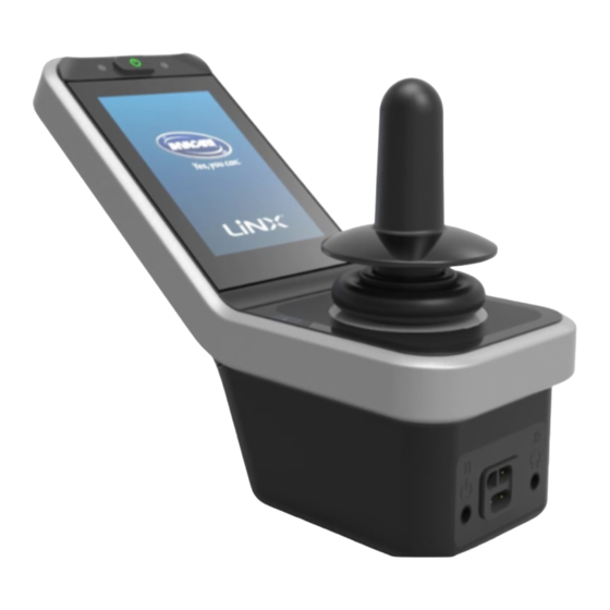
4 Components 4 Components 4.1 User Interface—REM400 Multipurpose buttons ON/OFF button/Status Touch display Joystick Bus socket Stereo jack sockets Infrared transmitter Speaker Charger socket Toggle switches 4.2 Screen Composition Overview Battery bar Status bar User function screen Navigation button 4.2.1 Battery Indicator The battery indicator provides a graphical display of the battery’s current state of charge and, when a battery charger is connected, the charging status. -
Page 13: Status Indicator
LiNX® Control System Battery bar displays green when state of charge is between 60 and 100%. Battery bar displays orange when state of charge is between 20 and 59%. Battery bar displays red when state of charge is less than 20%. Charging. -
Page 14: User Function Screen Overview
4 Components 4.3 User Function Screen Overview 4.3.1 Left- or Right-Handed With the LiNX system, it is possible to adjust the function screens for left-handed or right-handed users. Left-handed Right-handed In this manual, only right-handed function screens display. All buttons have the same functions for right- and left-handed users, so the descriptions can be used for left-handed users, too. -
Page 15: Drive Screen
LiNX® Control System Indicator Meaning Head Array Sip and Puff User Switch 4.3.3 Drive Screen Drive screens can be preset with different maximum speeds to fit your needs and your environment. For example, a drive screen with a preset lower maximum speed can be used indoors, and a drive screen with a preset total maximum speed can be used outdoors. -
Page 16: Seating Screen
4 Components 4.3.4 Seating Screen Seating screens are used to operate the seating functions. Refer to 6.16.1 Through Seating Screens, page 54. 4.3.5 Connectivity Screen Connectivity screens allow you to communicate with external devices. The connectivity function included on your remote is a mouse mover. -
Page 17: Arrangement
LiNX® Control System The utility screen allows you to operate system controls (such as the lighting functions and the horn), as well as control outputs with external inputs. The Utility screen function is suitable for both three-quadrant (3Q) and four-quadrant (4Q) inputs. The utility screen allows you to operate two controls/outputs per quadrant, according to the duration the user input is activated: A Short/Momentary press B Long press... -
Page 18: Navigation Button
4 Components 4.4 Navigation Button Depending on the configuration of the remote module and the user’s needs, the navigation button displays on the bottom-left or bottom-right of the screen. When activated, the navigation button changes color from grey to blue. The navigation button has two important functions: 1. - Page 19 LiNX® Control System Product label: 1. Part number 2. Dynamic Controls logo 3. Dynamic Controls part description 4. Dynamic Controls website address 5. Serial number 6. Warning to read manual before use 7. Ingress protection rating 8. WEEE symbol Hardware and application firmware version label: 1.
-
Page 20: Labels On Toggle Switches
4 Components Product label containing: Dynamic Controls website address Dynamic Controls Bluetooth registration 4.5.2 Labels on Toggle Switches Power Speed pot left Speed pot right Function and profile Seating Blank 4.5.3 Labels on Adaptive Switch Labs Parts Labels of Adaptive Switch Labs parts are located either on the left rear side of the part (head arrays) or on the interface box. Depending on the part, not all labels are available. -
Page 21: Serial Number And Date Of Manufacture
LiNX® Control System Product label (head array) containing: A: Adaptive Switch Labs logo B: Serial number Product label (interface boxes) containing: A: Model number B: Serial number C: Adaptive Switch Labs logo D: Adaptive Switch Labs contact information Product label containing: Adaptive Switch Labs Bluetooth registration Information about conditions 4.5.4 Serial Number and Date of Manufacture... -
Page 22: Setup
5 Setup 5 Setup 5.1 Connecting the Remote CAUTION! Risk of Unintended Stops If the plug of the remote cable is broken, the remote cable may come loose while driving. The remote could suddenly switch off when losing power. This results in an unintended stop. -Always check the plug of the remote for damage. -
Page 23: Usage
LiNX® Control System 6.1.3 Setting the Attendant Control 6 Usage If the wheelchair is fitted with an attendant control (ACU) and 6.1 Operating the Remote the attendant control is in charge, an attendant-in-charge overlay displays. 6.1.1 Powering Up the Remote Also, the status LED inside the primary remote ON/OFF button 1. -
Page 24: Menu Screen Controls
6 Usage The speedometer/odometer display is a new feature introduced for LiNX MR6.0. It replaces the sweeping Swipe-and-Tap Mode Tap Mode speed gauge that wrapped around the speed dial. Tap the top or bottom of the If both the firmware and the configuration are Slide the set point E speed slider D. -
Page 25: Switches
LiNX® Control System Fig. 6-1 Example of a button 1. Tap the button A to perform the action. Switches Switches are used to change between two different states, such as ON and OFF. The current state displays on the screen. Fig. -
Page 26: Menu Screen Settings
6 Usage 6.1.6 Menu Screen Settings The remote can be configured from the Menu screen. The Menu screen offers different settings to customize the display. Menu Structure The menu structure is shown below. Level 1 of the menu structure is on the left, and the sub-menus are in levels 2-4 to the right. For example, to adjust the brightness of the display, select Settings >... -
Page 27: Menu Screen
LiNX® Control System Menu Screen Label Entry Function Clock View and edit the time. Screen Activate the screen lock. Lock Activate Glove Mode. During Glove Mode, the touch screen becomes Glove more sensitive and allows user interaction with the screen while the Mode user is wearing gloves. -
Page 28: Display
6 Usage Display Label Entry Function Brightness Decrease or increase screen brightness. Language Change the Menu screen user interface to the selected language. Interaction Label Entry Function Tap- Only Toggle between tap mode and swipe-and-tap mode Mode Define the area used for detecting a tap action on the touch screen. It sets the area around the point of initial contact, within which a tap is recognized. -
Page 29: Audible Cues
LiNX® Control System Audible Cues Audible cues are sounds played through the REM400 remote speaker in response to certain system events or navigation actions performed by the user. They are designed to help users understand what function or profile they are using and are especially beneficial for: users with impaired vision or users who cannot see the display users who want additional feedback from their actions without the need to constantly monitor the display... -
Page 30: Menu Screen
6 Usage 6.1.7 Menu Screen Opening the Menu Screen 1. Tap and hold the Navigation button A until the Menu screen displays. Entry Function View and configure the time. See 6.1.8 Clock Configuring the Time, page 29. Closing the Menu Screen Activate the screen lock. -
Page 31: Locking The Screen To Avoid Unintentional Response
LiNX® Control System 3. If necessary, tap switch C to toggle between a 12- and 24- hour clock. 6.1.9 Locking the Screen to Avoid Unintentional Response The screen lock is a security feature the user can activate to prevent other people accidentally or intentionally interfering with the touch screen. -
Page 32: Navigating User Function Screens
6 Usage 3. Tap button E to close the Menu screen. 6.2.1 Function Change Inhibits Function change blocked is a safety feature that prevents accidental driving or seating movements when: a function change should be carried out when the user performs an action on the active function. -
Page 33: Using Tap Mode
LiNX® Control System Changing Profiles Using Tap Mode 1. Swipe up or down to activate another profile. Changing Function Screens The screen view focuses on the first function screen or the 1. Tap the Navigation button (short press) to open the screen last-used function screen in the profile, depending on how preview display. -
Page 34: Using A Control Input (Ci)
6 Usage 2. Tap the Navigation button or wait several seconds to Both menu select and menu scan provide two views to navigate activate the selected function screen. the menus: list view and grid view. List view displays the menu items in one of two vertically selectable lists. - Page 35 LiNX® Control System Menu Select List View Menu Select Grid View Action Result Mapping Action Result Mapping Menu Menu navigate navigate Forward to menu Forward item profile above above current current Menu Menu Down: Down: navigate navigate Reverse to menu Reverse item profile...
-
Page 36: Navigation Entry
6 Usage Short Select Menu Scan Grid View left function Action Result Mapping Long Exit left Menu Select Right: quadrant menu navigate or left, Short item right right function right of current Menu Select Down: quadrant menu navigate or left, Long item right... -
Page 37: Menu Select With 4Q Operation
LiNX® Control System If the Navigation entry is set to First Profile, the menu 6. Give right input D to select the function screen. selection starts at the first profile in the Profile menu. You select a profile before moving into the selected profile’s Function Screen menu. -
Page 38: Menu Select In Grid View
6 Usage 6. To return to the Profile menu, give right input until the Back button D is selected. Give left input to go back to the Profile menu. 7. Give left input C to select the function screen. 4Q users can navigate through the menu in both directions vertically (up/down) and both directions horizontally (left/right). -
Page 39: Scan Select Overview
LiNX® Control System 6.2.5 Scan Select Overview Selected Profiles Function Screens Function Screen Navigation Entry Navigation Entry First Profile Active User Function Select No selection function screen One iteration Select Select function profile screen No selection No function screen selected Select Timer Navigation Entry—Menu Select... - Page 40 6 Usage If Navigation Entry is set to First Function in Active Profile, the menu selection starts at the first function in the currently selected profile. From here the user chooses to navigate the function menu, select a function or move up into the profile menu and select a different profile.
-
Page 41: Scan Select
LiNX® Control System 6.2.6 Scan Select If Navigation entry is set to First Profile, the first item in With scan select, the system performs the navigation and you the profile menu displays on the touch screen. If this item select the function screen. Scan select provides you with a is not selected, the system iterates through the profile semi-automated process for navigating through the profiles and menu until a profile is selected or until the number of... -
Page 42: Using The Multipurpose Buttons
6 Usage 1. Press the left button A to switch to the next profile. 2. Press the right button B to switch to the next function screen. 6.4 Using the Toggle Switches (Optional) Like menu select, it is possible to go back from the function screen menu to the profile menu or close the profile menu. -
Page 43: Joystick Shaping
LiNX® Control System When the joystick is deflected from the neutral (center) position, the wheelchair moves in the direction of the joystick movement. The speed of the wheelchair is proportional to the joystick deflections. That is, the farther the joystick moves from the neutral position, the faster the wheelchair travels. -
Page 44: Using Latched Driving Mode
-the Latch Drive Timeout is expired To avoid potentially dangerous situations, Invacare recommends to make yourself familiar with the latched driving mode, especially with the commands to stop the wheelchair. -
Page 45: Turn Commands
LiNX® Control System The term command, mentioned in this manual, means the input depending on the type of 5 Step Up/Down control, e.g. joystick movements or sip and puff commands. Refer to 6.19.6 Using the Sip and Puff Head Array, page 75 for more information about the Sip and Puff Head Array. -
Page 46: Step Up
6 Usage The wheelchair does not drive until the external stop 6.6.4 3 Step Up switch test is completed successfully. 6.6.3 1 Step Up In this mode, you can step through one of three fixed speeds. The speeds available are 33%, 67% and 100% of the maximum preset reverse or forward speed A of the selected drive screen. -
Page 47: Step Up
LiNX® Control System 6.6.5 5 Step Up 6.6.6 3 Step Up/Down In this mode, you can step up or down through one of three In this mode, you can step through one of five fixed speeds. The fixed speeds. The speeds available are 33%, 67% and 100% of speeds available are 20%, 40%, 60%, 80% and 100% of the the maximum preset reverse or forward speed A of the maximum preset reverse or forward speed A of the selected... -
Page 48: Step Up/Down
6 Usage 6.6.7 5 Step Up/Down 6.6.8 Cruise Control In this mode, you do not have fixed steps and can choose the In this mode, you can step up or down through one of five fixed latched speed yourself. The speed is maintained for the speeds. -
Page 49: Operating The Position Lights
LiNX® Control System 3. Tap button C to close the Lighting button panel. 6.8 Operating the Position Lights If you drive outside, turn on the position lights in bad visibility conditions or darkness. To operate the position lights, you must stop the mobility device. -
Page 50: Operating The Hazard Lights
6 Usage If you start driving, the Lighting button panel overlay closes. 6.9 Operating the Hazard Lights To operate the hazard lights, you must stop the mobility device. 6.9.1 Turn On the Hazard Lights 1. Tap the Lighting control button A 3. -
Page 51: Operating The Turn Signals
LiNX® Control System 2. Tap the Hazard lights symbol B . The left or right indicator icon becomes illuminated in the lighting dashboard. If you start driving, the Lighting button panel overlay closes. 6.10 Operating the Turn Signals To operate the turn signals, you must stop the mobility device. -
Page 52: Turn Off The Turn Signals
6 Usage 6.10.2 Turn Off the Turn Signals 6.11 Operating the Horn 1. Tap the Lighting control button A. 1. Tap the Horn button A to sound the horn. 2. Tap the left turn signal symbol B or the right turn signal symbol C to turn off the turn signal. -
Page 53: Locking/Unlocking The Remote
LiNX® Control System Give a short demand to left C to turn on/off the hazard can be used again. lights. Give a long demand to left or right D to turn on the left or right turn signal. Give a short demand to turn off the turn signal. -
Page 54: Entering Rest From A Drive Or Seating Function Via Timeout
6 Usage Menu select via timeout Although the partly disabled mode does not provide the same extent of confidence as the fully disabled mode, it is useful for Menu navigation via control input those users that require quick access to valued or often-used Entry to rest is prohibited when a system is being functions and actions. -
Page 55: Through Seating Screens
LiNX® Control System 6.16.1 Through Seating Screens By default, every seating screen displays a single powered seating function. Different configurations are Powered recline listed below. Contact your provider to change the configuration. Seat lifter Left or center-mount powered elevating legrest Right powered elevating legrest Choose the seating screen with the seating function you want to operate. -
Page 56: Through External Switches
6 Usage All four quadrants are used for operating powered seating 6.16.2 Through External Switches Not all configurations and combinations of powered functions. seating functions through external switches are 1. Give and hold a forward A, reverse C, left D or right available on all products. -
Page 57: Egg Switch
LiNX® Control System Egg Switch 2. Deflect and hold the toggle switch up A or down B to move a particular seating function. The egg switch alternates powered seating functions of the The seating function moves as long as the toggle switch is following single power configurations: deflected. -
Page 58: 4-Way Button Switch
6 Usage The tables show the factory settings. For 4–way Button Switch reprogramming, contact your provider. Powered Seat Tilt and Powered Recline A (Forward) Powered seat tilt up B (Reverse) Powered seat tilt down C (Left) Powered recline up D (Right) Powered recline down Powered Seat Tilt, Recline, Elevate and Legrest A (Forward) -
Page 59: 10-Way Switch
Powered legs down 6.16.3 Speed Reduction and Seating Function Inhibits The mentioned speed reduction and seating function limits do not apply to all Invacare wheelchair models. Speed Reduction If the elevating seat is adjusted above a certain point, the drive electronics considerably reduce the speed of the wheelchair. -
Page 60: Seating Function Inhibits
6 Usage Speed reduction is shown in the display. If the elevating seat is raised above a certain point, an icon with an exclamation point displays in the status bar. This indicator remains active until speed reduction is deactivated by lowering the elevating seat. Seating Function Inhibits Tilt Limit The seating electronics are equipped with an elevating seat... -
Page 61: Pairing A Mobile Device With The Linx System
LiNX® Control System 1. Long press the Navigation button A. 4. Tap the Pair New Device button F at the bottom of the menu. 2. On the status display, open the Settings menu B. The pairing passkey and the LiNX device name you are pairing with display on the touch screen. -
Page 62: Pairing A Pc Or Laptop With A Linx System
6 Usage Pairing a PC or Laptop with a LiNX System Perform this operation promptly following the pairing process on your remote (see Pairing the LiNX System with a User’s Device, page 59); otherwise, a timeout will occur. 1. Open the Devices and Printers dialog box on your Windows PC or laptop by selecting one of the following: Start >... -
Page 63: Linking The Connectivity Card With The User's Device
LiNX® Control System The LiNX system permits up to 10 devices to be paired at any time. If you reach this limit and need to add more devices, consider forgetting paired devices. See Removing Paired Devices, page 63. Linking the Connectivity Card with the User’s Device Connectivity cards must be linked to a paired device. -
Page 64: Connecting Devices With The Linx System
6 Usage Removing Paired Devices 1. Long press the Navigation button A. 7. Select a paired device in the list E, or tap the Pair New Device button F to pair with a new device. A green hook behind the device name identifies an active device. 2. -
Page 65: Selecting A Connectivity Card
LiNX® Control System 6. Tap the Forget this Device button again, or tap the Cancel button to cancel the removal operation. 4. In the Paired Devices section ,select the paired device (for example, laptop D) you want to remove. Selecting a Connectivity Card For more information about selecting user function cards, see 6.2.2 Direct Navigation, page 31 or 6.2.3 Indirect Navigation, page 33. -
Page 66: Mouse Mover
6 Usage 6.17.2 Mouse Mover The Bluetooth status indicator Connectivity shows the status of screen name the Bluetooth Mouse move connection indicator between the LiNX Bluetooth system and your status Left mouse device: button disconnected Right mouse connecting button connected Scroll indicator Setting up a Mouse Mover... - Page 67 LiNX® Control System 2. On the Status display, open the Settings menu B. For each mouse mover function, you can set the following cursor settings: Fast Cursor Speed Slow Cursor Speed Slow Movement Time 3. From the Settings menu, open the Connectivity menu C. 4.
-
Page 68: Operating The Mouse Mover
6 Usage Fast Cursor Speed E: Sets the speed at which the mouse cursor 1. Press and hold the scroll mode button. ramps D up after the Slow Movement Time F expires. During 2. Use the assigned user input or programmed control inputs the Slow Movement Time, however, the mouse cursor speed to perform up and down scroll actions. -
Page 69: Switch Control Setup
LiNX® Control System Linking the switch control connectivity screen with the The name can be Connectivity user's device used to uniquely screen identify this Configuring switch control name screen’s purpose. Configuring Switch Control The Bluetooth Before you can use switch control, you must identify the status indicator switches you will use and assign an action to each switch. -
Page 70: Configuring Switch Control (Ios)
6 Usage Configuring Switch Control (iOS) 4. Activate the external switch. For example, tap the touch 1. Open the switch control menu on your mobile device. screen or deflect the joystick to the left. Settings > General > Accessibility 2. Open the Switches menu. 5. -
Page 71: Switch Control Operation
LiNX® Control System 7. Assign an action to the switch. From the Actions menu, choose a switch action, such as Select Item. 4. Tap External. You are prompted to activate the external switch. 8. If required, repeat the previous steps to add more 5. -
Page 72: Secondary Inputs
6 Usage Driving 6.19 Secondary Inputs CAUTION! 1. Deflect the drive joystick A from the neutral position to Risk of Injury drive in the desired direction. If an external input is used, unrequested functions or speed settings can lead to unexpected operations. -To avoid unexpected operations, check which function is operated and the function speed setting. -
Page 73: Operating The Lighting Functions And Horn
LiNX® Control System For operating the powered seating functions, refer to 6.16.1 For more information about driving, refer to 6.5 Using Through Seating Screens, page 54. Proportional Driving Mode, page 41. Operating the Lighting Functions and Horn Changing Function Screens Via a utility function screen, you are able to operate the lighting For information about the difference between the functions with an external input. -
Page 74: Using The Micro Extremity Control Joystick
6 Usage 3. Give a short input to the right B to turn on/off the For information about operating the powered seating position lights. functions, refer to 6.16.1 Through Seating Screens, page 54. 4. Give a short input to the left C to turn on/off the hazard Operating the Lighting Functions and Horn lights. -
Page 75: Changing Function Screens
As necessary, replace mouthpiece, breath tube and saliva trap. Contact your Invacare provider for more information about maintaining and troubleshooting the Sip and Puff system. For maintenance and cleaning instructions, see Maintenance, page 1. -
Page 76: Stopping
6 Usage 1. Activate the utility function screen. 1. Puff hard into the mouthpiece A to drive forward. 2. Give input to the front A to turn on the horn. 2. Sip hard at the mouthpiece to drive in reverse. 3. -
Page 77: Driving
As necessary, replace mouthpiece, breath tube and saliva trap. 3. When in latched driving mode, activate the left pad B to Contact your Invacare provider for more information veer to the left. about maintaining and troubleshooting the Sip and 4. When in latched driving mode, activate the right pad C to Puff system. -
Page 78: Operating The Lighting Functions And Horn
6 Usage 6.19.7 Using the Head Array WARNING! Risk of Serious Injury Proximity sensors are sensitive to water. If enough water is present close to the sensors, they may be activated and the mobility device may start moving unintentionally. -Do not operate Head Array with wet hair. -Do not operate Head Array in wet weather. -
Page 79: Driving
LiNX® Control System Driving Forward Reverse Forward Active Reverse Active 1. Activate the forward drive function screen. Activate the center pad A to drive forward. 2. Change to the reverse drive function screen. Activate the center pad A to drive in reverse. 3. -
Page 80: Operating The Lighting Functions And Horn
6 Usage Operating the Lighting Functions and Horn By default, the sensors power up as soon as the wheelchair is powered up and power down as soon as the wheelchair is Via a utility function screen, you are able to operate the lighting powered down. -
Page 81: Operating The Lighting Functions And Horn
LiNX® Control System 1. Activate the utility function screen. Forward Reverse 2. Give input to the front A to turn on the horn. Forward Active Reverse Active 3. Give short input to the right B to turn on/off the position lights. - Page 82 6 Usage Dip switch 1 & 2: Initial mouse movement medium medium slow fast This is a slower speed initially for precise targeting. It fast slow is set and used in conjunction with Cursor Delay to give the user the ability to move the mouse slowly at Dip switch 3 &...
-
Page 83: Disabling Bluetooth
LiNX® Control System Input Direction Mouse Action Left click No change Right click No change Input direction/Mouse action (0–6) cannot be duplicated in any two switches, except for zero. 6.20 Disabling Bluetooth The embedded Bluetooth functionality can be disabled when powering up the system. -
Page 84: Battery Alarms
6 Usage Over voltage This displays if the batteries are overcharged. Disconnect the battery charger immediately. Low voltage This displays if the batteries are empty. Power down the wheelchair, and charge the batteries immediately. Deep discharge This displays if the battery voltage falls below the voltage set by Cut Off Voltage. - Page 85 LiNX® Control System 1. Open the bung A. 2. Connect the device with the USB port. Replace the bung when the USB ports are not in use. Use of the USB charger influences the drive range of the mobility device. For more information about the drive range, refer to the Technical Data chapter in the mobility device user manual.
-
Page 86: Maintenance
Check for and remove any foreign objects or material. 7.3.3 Inspect/Adjust Periodically Check the joystick boot for damage. Contact your Invacare provider for replacement if it is damaged. Check that all labels are present and legible. Replace them if necessary. -
Page 87: Six-Month Inspection
LiNX® Control System 7.4.1 Six-Month Inspection WARNING! Risk of Death or Serious Injury Failure to complete the inspection of the critical components listed below could result in death or serious injury. -Inspect stability control components, which could include anti-dive spring, anti-dive cylinder, ratcheting gears, or end stops to ensure proper operation. -
Page 88: Replacing The Mouthpiece
7 Maintenance 1. Remove the mouthpiece A and lipswitch C from the gooseneck B. 2. Remove the breath tube from the saliva trap. See 7.7 Replacing the Saliva Trap, page 88. 3. Position the catch can beneath the breath tube to collect water, and rinse. 4. -
Page 89: Replacing The Saliva Trap
LiNX® Control System 7.7 Replacing the Saliva Trap Risk of Damage to the Input Module If the saliva trap is inserted the wrong way round, the input module can be damaged by water or saliva. -Make sure to insert the saliva trap in the correct orientation. -Saliva trap MUST be installed to reduce risk of water or saliva entering the input module. -
Page 90: Troubleshooting
8 Troubleshooting 8 Troubleshooting 8.1 Fault Diagnosis If the electronic system shows a fault, use the following fault-finding guide to locate the fault. Ensure the drive electronics system is powered up before starting any diagnosis. If the Status Display is OFF: Check whether the drive electronics system is powered up. -
Page 91: Oon ("Out Of Neutral")
LiNX® Control System Fault Icon Fault Description Possible Action Check cables and connectors. Ensure the left magnetic brake is engaged. Ensure the left motor or motor lock lever is engaged. Left magnetic brake fault Refer to the “Pushing the mobility device in freewheel mode” chapter in the wheelchair user manual. -
Page 92: Seating Oon Warning
8 Troubleshooting 8.2.2 Seating OON Warning When a system is powering up or after a function change, no direct access switches can be active; otherwise, a seating OON warning displays. During a seating OON warning, the OON overlay displays and the seating motions do not operate. If the switches are deactivated, the warning clears and the seating motions operate normally. -
Page 93: Technical Data
LiNX® Control System 9 Technical Data 9.1 Technical Specifications 9.1.1 Mechanical Specifications Permissible Operating, Storage and Humidity Conditions Temperature range for operation according to -13°F (-25°C)-122°F (+50°C) ISO 7176-9: Recommended storage temperature: 59°F (15°C) Temperature range for storage according to ISO -40°F (-40°C)-149°F (+65°C) 7176-9: Operation humidity range according to ISO 7176-... -
Page 94: Wireless Technology
10 Wireless Technology 10 Wireless Technology 10.1 Wireless Technology Overview The LiNX control system uses Bluetooth wireless technology. Bluetooth is a wireless communications system that is designed to operate in short-range wireless personal area networks (WPAN). LiNX supports both the Smart (low energy) and Classic Bluetooth protocols. These operate in the spectrum range 2.400 GHz to 2.4835 GHz industrial, scientific and medical (ISM) band. -
Page 95: Remote Diagnostics
LiNX® Control System 10.3.2 Remote Diagnostics The system transmits wheelchair-specific diagnostic information to an Apple iOS device. This information helps with the technical support of the wheelchair. The information provides the status of the wheelchair electronics, including: Battery charge status Active and historical fault data Wheelchair driving time Information about the modules attached to the wheelchair (e.g., module serial numbers) -
Page 96: Safeguards And Redundancy
10 Wireless Technology Loss of configuration data transmitted in programming and diagnostic mode would result in no effect. The existing wheelchair configuration would be maintained. Errors in the configuration data transmitted would be rejected by built-in safety mechanisms and/or detected during the subsequent evaluation of the configuration updates through the prescribed user testing. The programming and diagnostic tools serve no specific medical purpose and do not control the wheelchair's operation. -
Page 97: User Actions
LiNX® Control System ◦ Limited exposure time ◦ Visual indication when in a connectivity function 10.6.2 User Actions Users are not required to take any specific actions in order to assure cybersecurity of the LiNX system. However, should the user be concerned about the Bluetooth connection for any reason, the user can switch off the Bluetooth functionality by powering down the system. -
Page 98: Warranty
Except as otherwise set forth below, Invacare warrants that the following components of the mobility device (“product”) will be free from defects in materials and workmanship for a period of one (1) year from the date Invacare ships the product to the original... - Page 99 LiNX® Control System The Warranty does not apply to problems arising from normal wear and tear or failure to adhere to the product instructions. A change in operating noise, particularly relative to motors and gearboxes does not constitute a failure or defect and will not be repaired or replaced as all products are expected to exhibit changes in operating noise due to aging.
- Page 100 11 Warranty Notes 60126081-C...
- Page 101 Invacare Corporation One Invacare Way, Elyria, OH 44035, USA • 800-333-6900 • www.invacare.com Canada 570 Matheson Blvd E Unit 8, Mississauga, Ontario, L4Z 4G4 Canada • 800-668-5324 • www.invacare.ca Manufacturer Invacare Corporation • One Invacare Way • Elyria, OH 44035, USA Dynamic Controls •...