
Related Manuals for Invacare LiNX DLX-REM500


Summary of Contents for Invacare LiNX DLX-REM500
- Page 1 Invacare® LiNX DLX-REM500 en Remote User Manual This manual MUST be given to the user of the product. BEFORE using this product, this manual MUST be read and saved for future reference.
- Page 2 All rights reserved. Republication, duplication or modification in whole or in part is prohibited without prior written permission from Invacare. Trademarks are identified by ™ and ®. All trademarks are owned by or licensed to Invacare Corporation or its subsidiaries unless otherwise noted.
-
Page 3: Table Of Contents
Contents 5.4 Using Direct Navigation ......30 5.4.1 Swipe-and-Tap Mode ......31 5.4.2 Tap-Only Mode . - Page 4 5.19 Connectivity Cards......73 5.19.1 Configuring Connectivity Card ....74 5.19.2 Mouse Mover .
-
Page 5: General
1.1 About This Manual For more information about the component, for example safety notices and recalls, contact your Invacare This document is a supplement to the product’s user representative. See addresses at the end of this document. -
Page 6: Warranty Information
Identifies required tools, components and items which are needed to carry out certain work. 1.5 Limitation of Liability Invacare accepts no liability for damage arising from: Other Symbols (Not applicable for all manuals) • Non-compliance with the user manual •... -
Page 7: Safety
Safety 2 Safety WARNING! Risk of injury or damage due to electrical shorts Connector pins on cables connected to the power 2.1 General safety notes module can still be live even when the system is off. WARNING! – Cables with live pins should be connected, Risk of injury or damage to the mobility device restrained or covered (with non-conductive Do not install, maintain or operate this equipment... - Page 8 Invacare® LiNX CAUTION! Risk of injury due to unintended movement It is recommended that the mobility device, fitted with a Gyro module, has a drive function with disabled Gyro. If the mobility device is used in a moving vehicle (e.g. boat, bus or train) maybe the Gyro function is impaired and drive demands can result in unintended movement.
-
Page 9: Components
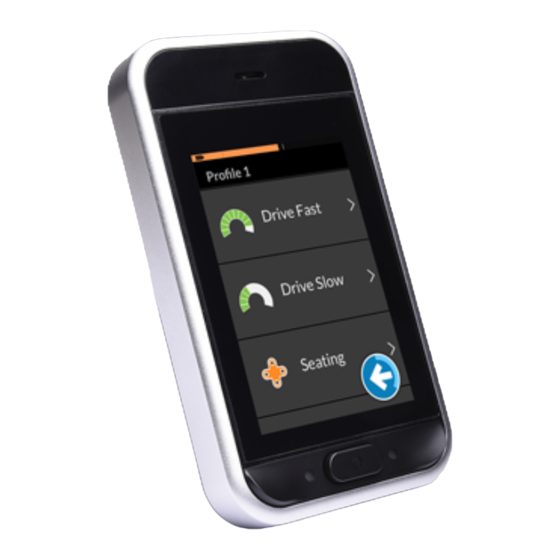
Components 3 Components G Bus socket H Infrared transmitter 3.1 User interface DLX-REM500 3.2 Screen composition overview A Battery bar B Status bar C User function card A Multipurpose buttons D Navigation button B ON/OFF button/Status LED E Function information C Touch display 3.2.1 Battery bar D Speaker... -
Page 10: Status Bar
Invacare® LiNX programming and diagnostic tool. The country-based offset Battery bar displays green is set through the remote module’s Menu screen. See 5.2.4 when state of charge is Configuring Settings, page 27. between 60 and 100%. Status Information Battery bar displays orange... -
Page 11: User Function Card Overview
Components This notifies you that a seating lock-out is active. A seating lock-out is a state that prevents the wheelchair’s seating being operated. See 5.18.3 Speed Reduction and Seating Function Inhibits, page 71 for more information about lock-outs and slow-downs. This notifies you that Bluetooth connectivity is disabled. - Page 12 Invacare® LiNX The text B is programmable by your provider and can be Drive Card used to name the function. Indicator Meaning DLX-REM400 DLX-REM500 DLX-REM2xx DLX-CR400 DLX-CR400LF DLX-ACU200 Fig. 3-5 Input module or Drive cards can be pre-set with different maximum speeds third-party interface to fit your needs and your environment.
- Page 13 Components Seating Card Speedometer displays standstill. While driving, the speedometer displays the wheelchair’s current speed. The odometer displays the distance travelled by the wheelchair since it was last reset to zero or rolled over to zero. The odometer can display up to a maximum distance of 9999 km or miles, after which it rolls over to zero.
- Page 14 Invacare® LiNX your remote are Mouse Mover and Switch Control. By external inputs. The utility card function is suitable for both default, these functions are disabled. Contact your provider three-quadrant (3Q) and four-quadrant (4Q) inputs. to change the configuration. Utility card allows you to operate two controls / outputs...
-
Page 15: Navigation Button
Components Arrangement When activated, the navigation button changes its color from grey to blue. Function cards The navigation button has two important functions: 1. A visual indication of the configured interaction mode. Configured for swipe-and-tap actions This means, that swiping and tapping the screen Pro- activates different functions. -
Page 16: Labels On The Product
Invacare® LiNX 3.4 Labels on the Product Product label containing: Labels on Dynamic Controls’ Parts 1. Part number 2. Dynamic Controls logo Labels of Dynamic Controls’ parts are located on rear side of 3. Dynamic Controls’ part the part. Depending on the part not all labels are available. - Page 17 Components Product label containing: • Dynamic Controls' website address The format, as shown above, is MYYnnnnnn, where: • Dynamic Controls’ Bluetooth registration • M is for the month of manufacture, using the letters A to L (A = Jan, B = Feb, C = Mar, etc.), Tamper evident seal.
- Page 18 Invacare® LiNX Product label (head array) containing: • A: Adaptive Switch Labs’ logo • B: Serial number Product label (interface boxes) containing: • A: Model number • B: Serial number • C: Adaptive Switch Labs’ logo • D: Adaptive Switch Labs’...
-
Page 19: Setup
Setup function, and then activate a different output when the 4 Setup system is in another state or function. For example, a buddy button that is used to stop a wheelchair when driving can 4.1 General information on setup also be used to extend a seating motion when in a seating The tasks described in this chapter are intended to be function. -
Page 20: Connecting The Remote
Invacare® LiNX Adequate strain relief must be provided for all cables, and be minimized wherever possible, to extend service life and the mechanical limits of the cables and looms must not be minimize the risk of accidental damage. exceeded. Risk of damage to bus cable... - Page 21 Setup Risk of damage to the remote The remote plug and connector socket fit together in one way only. – Do not force them together. 1. Lightly push to connect the plug of the remote cable and the connector socket. The plug must lock in place with an audible click.
-
Page 22: Usage
Invacare® LiNX information about fault indication, refer to 7.1.1 Fault Codes 5 Usage and Diagnosis Codes, page 117 . 5.1 Powering Up/Down Remote Powering Down Remote Powering Up Remote 1. Press ON/OFF key A. Fig. 5-1 Press ON/OFF key A. -
Page 23: Menu Screen
Usage If your wheelchair is fitted with an attendant control Closing Menu Screen (DLX-ACU200) and the attendant control is in charge, an attendant-in-charge-overlay is displayed. Also the status LED inside the ON/OFF button of the primary remote is turned off. 1. -
Page 24: Controls On Menu Screen
Invacare® LiNX Entry Function Symbol Action A Clock View and configure time, see 5.2.2 Close screen Configuring Time, page 25. B Screen Lock Activate screen lock, see 5.2.3 Go back to previous screen Locking Screen to Avoid Unintentional Response, page 26. -
Page 25: Configuring Time
Usage Fig. 5-10 Example of a slider 1. Tap and hold circle A within the slider. 2. Swipe circle to the right to increase the value. Swipe Fig. 5-12 circle to the left to decrease the value. If necessary, tab switch C to toggle between 12– and 5.2.2 Configuring Time 24–hour clock. -
Page 26: Locking Screen To Avoid Unintentional Response
Invacare® LiNX Fig. 5-15 Fig. 5-16 Tap on button D to return to Menu screen. Tap and hold navigation button A to open Menu screen. 5.2.3 Locking Screen to Avoid Unintentional Response The screen lock is a security feature that the user can activate to prevent other people accidentally or intentionally interfering with the touch screen. -
Page 27: Configuring Settings
Usage Screen lock is activated. Display Turn remote off and on (power-cycle) to deactivate screen lock. Keep the touch screen dry to ensure proper response during use. 5.2.4 Configuring Settings Settings menu allows you to change settings in different Fig. 5-20 categories: Entry Function... - Page 28 Invacare® LiNX Entry Function A Tap-Only Mode Toggle between tap-only mode and swipe-and-tap mode. B Tap Zone Defines the area used for detecting a tap action on touch screen. It sets the area around the point of initial contact, within a tap is Fig.
-
Page 29: Configuring Odometer
Usage Entry Function D Units selector C Left Hand Toggle between right-hand and E Back Mode left-hand usage of remote. The total distance meter shows the cumulative value of all When the switch is set to ON, all trips. user controls (navigation button, speed slider, lighting controls etc) The total distance meter cannot be reset from this are displayed and operable from the... -
Page 30: Selecting Functions
Invacare® LiNX Changing Units How to navigate through the LiNX system depends on how the navigation button is configured. Refer to 3.3 Navigation 1. Tap on units selector D to change displayed units. mi button, page 15, for more information about the possible for miles, km for kilometres. -
Page 31: Swipe-And-Tap Mode
Usage • swipe-and-tap mode, Changing Profiles • tap-only mode and • control inputs (CI). With each method you navigate through profiles and functions by moving from an active function card to an Profile 1 adjacent function card. Fig. 5-29 Direct navigation is not performed with an active user input (e.g. -
Page 32: Tap-Only Mode
Invacare® LiNX The screen view focuses on the first function card or the last-used function card in the profile, depending on Profile 1 how the programming is set up. 2. Swipe left or right to change function cards. Fig. 5-35 3. -
Page 33: Control Input (Ci)
Usage The screen view focuses on the first function card or List View the last-used function card in the profile depending on how the programming is set up. 2. Tap on navigation button or wait for a few seconds to activate selected function card. - Page 34 Invacare® LiNX Grid View Fig. 5-41 If Navigation Timeout is enabled by your provider, the Fig. 5-40 indirect navigation is automatically entered after a period of Grid view presents the menu items in a single grid, displaying time without user activity. This period can be set by your both the profiles (rows) and the functions (columns) at the provider and is displayed with a timeout indicator A.
-
Page 35: Quadrant Mapping
Usage function card when in the first function card of the profile, instead of wrapping to the next/previous function, the navigation menu is entered. That is when selecting the next function card while in the last function card in a profile or when selecting the previous 5.5.1 Quadrant Mapping Similar to the drive function, there is a difference between a three-quadrant (3Q) and a four-quadrant (4Q) operation. -
Page 36: Menu Select
Invacare® LiNX 5.5.2 Menu Select 4Q Operation in List View 1. Enter navigation. With menu select, you perform both, the navigation and the function card selection. List View Grid View Fig. 5-46 Give forward demand A or reverse demand B to switch between profiles. - Page 37 Usage 3Q Operation in List View 1. Enter navigation. Fig. 5-47 Give right demand D to select profile. Function card menu opens. Give forward demand A or reverse demand B to switch between function cards. Give left demand C to switch back to previous menu. Fig.
- Page 38 Invacare® LiNX 5. To go back to profile menu, give right demand until 4Q Operation in Grid View Back button D is selected. 1. Enter navigation. Give left demand to go back to profile menu. Fig. 5-51 Give left demand C to select function card.
-
Page 39: Navigation Entry Points In Menu Select
Usage 3. Give short left demand to select function. 4. Give long left demand to exit navigation. 5.5.3 Navigation Entry Points in Menu Select List View NEP = Navigation Entry Point FC = Function Card Selected FC NEP: First Profile NEP: First Function in Active Profile select profile select FC... -
Page 40: Menu Scan
Invacare® LiNX Grid View First Profile Active User Function First Function in Active Profile Fig. 5-53 Fig. 5-54 Fig. 5-55 There are different navigation entry points: • If Navigation entry is set to First Profile, the menu selection starts at the first function in the first profile. From here you can choose to navigate between functions and profiles before selecting a function. - Page 41 Usage The system can enter the idle state from either the profile menu or the function card menu. To exit the idle state, you must provide a select demand. When exiting the idle state, the system returns to the profile or function menu depending on the Navigation entry setting.
- Page 42 Invacare® LiNX When in profile list, the exit button is highlighted after Operation in Grid View highlighting the last profile in the list. When in the function list, the back button is highlighted after highlighting the last function in the list.
-
Page 43: Navigation Entry Points In Menu Scan
Usage 5.5.5 Navigation Entry Points in Menu Scan Navigation Entry Point = NEP Profiles Function cards (FC) Selected FC NEP: Active User Function NEP: First Profile select FC One iteration NEP: 1st Function in Active Profile no selection select FC One iteration select profile select FC... - Page 44 Invacare® LiNX • If Navigation entry is set to First Profile, the first item in the profile menu is displayed on the touch screen. If this item is not selected, the system iterates through the profile menu until a profile is selected or until the number of iterations is reached, at which point the system displays the idle state.
-
Page 45: Using The Multipurpose Buttons
Usage 5.6 Using the multipurpose buttons The external joystick controls the direction and the speed of the wheelchair. Fig. 5-61 When the external joystick is deflected from the neutral By default, you can change profiles and function cards with (center) position, the wheelchair moves in the direction of the multipurpose buttons. - Page 46 Invacare® LiNX Proportional Driving Mode Discrete Driving Mode The speed of the wheelchair is pre-set by controlling the maximum speed, refer to 5.7.2 Controlling Maximum Speed, page 47. Fig. 5-63 The speed is activated when the external joystick is deflected past a configurable threshold B into either the forward A Fig.
-
Page 47: Controlling Maximum Speed
Usage 5.7.2 Controlling Maximum Speed In each drive card you are able to control the pre-set maximum speed depending on your needs. Fig. 5-64 The speed dial is divided into ten segments, representing Fig. 5-65 the speed range of the wheelchair. Each segment can be displayed in one of three colors. -
Page 48: Latched Driving Mode
Invacare® LiNX Fig. 5-66 Fig. 5-67 As soon as you start driving, speed slider and navigation The speedometer/odometer display is a new button disappear from the display. The current speed is feature, introduced for LiNX MR6.0, and replaces the displayed by the speedometer, if it is enabled. - Page 49 There are six latched driving modes, which are indicated on the lower left of the drive card with To avoid potentially dangerous situations Invacare the symbols displayed in the table below. recommends to make yourself familiar with the...
-
Page 50: External Stop Switch
Invacare® LiNX External stop switch test 5 Step Up/Down The external stop switch test checks that the external stop switch is functioning correctly. The test is conducted once per power cycle when: Cruise Control • the wheelchair is powered up in a latched drive mode function or •... -
Page 51: Step Up
Usage 5.8.2 1 Step Up Normal Rate 1. Give long drive demand, greater than one second, in opposite direction (a reverse demand when driving forwards or a forward demand when driving in reverse) press external stop switch. Gentler Rate 1. Give short drive demand, less than one second, in opposite direction (a reverse demand when driving forwards or a forward demand when driving in reverse) Fig. -
Page 52: Step Up
Invacare® LiNX 5.8.3 3 Step Up Decelerating When stopping, the speed decelerates to zero at one of two rates (normal or gentle), depending on how the deceleration is triggered (long or short demand) and if the optional slower rate is configured by the provider. -
Page 53: Step Up
Usage 5.8.4 5 Step Up Decelerating When stopping, the speed decelerates to zero at one of two rates (normal or gentle), depending on how the deceleration is triggered (long or short demand) and if the optional slower rate is configured by the provider. Normal Rate 1. -
Page 54: Step Up/Down
Invacare® LiNX 5.8.5 3 Step Up/Down 3. Give forward demand when driving forwards or reverse demand when driving in reverse to accelerate to next fixed higher speed. Give reverse demand when driving forwards or forward demand when driving in reverse to decelerate to next fixed lower speed. -
Page 55: Step Up/Down
Usage Interrupting Deceleration Accelerating 1. Give drive demand in desired direction (forward or When slowing down or stopping (except for an emergency reverse). stop or control input configured for a stop), the deceleration 2. Release drive demand. can be interrupted to resume driving. Wheelchair speed accelerates to 20 % of the maximum 1. -
Page 56: Cruise Control
Invacare® LiNX Gentler Rate Accelerating/Decelerating 1. Give short drive demand, less than one second, in 1. Give and hold drive demand in direction (forward or opposite direction (a reverse demand when driving reverse) until wheelchair accelerates to desired speed. forwards or a forward demand when driving in reverse) 2. -
Page 57: Emergency Stop
Usage 1. Give two short drive demands (less than one second) in Tap Lighting control button A. same direction to stop at a normal deceleration rate. 2. Give and hold drive demand in opposite direction (reverse when driving forwards or forward when driving in reverse) until mobility device stops. -
Page 58: Operating The Hazard Lights
Invacare® LiNX 5.11 Operating the hazard lights Turn off position lights To operate the hazard lights, you need to stop the mobility device. Turn on hazard lights Tap Lighting control button A. Tap Lighting control button A. Lighting button panel overlays screen. - Page 59 Usage Turn off hazard lights Hazard lights turn on. Hazard lights telltale becomes illuminated in the lighting dashboard. Tap Lighting control button A. 3. Tap button C to close Lighting button panel. If you start driving, the Lighting button panel overlay disappears automatically and the hazard lights remain turned on.
-
Page 60: Operating The Direction Indicators
Invacare® LiNX 5.12 Operating the direction indicators To operate the direction indicators, you need to stop the mobility device. Turn on direction indicators Either left or right direction indicator turns on. Left or right indicator telltale becomes illuminated in the lighting dashboard. -
Page 61: Operating The Horn
Usage 5.13 Operating the horn Turn off direction indicators Tap Lighting control button A. 1. Tap horn button A to sound horn. Horn sounds as long as button is tapped. 5.14 Operating Lighting Functions and Horn via Utility Function Card Via a utility function card you are able to operate the lighting functions and horn with an external input. -
Page 62: Locking/Unlocking The Remote
Invacare® LiNX Locking the remote Fig. 5-74 • Give forward demand A to sound horn. Fig. 5-75 • Give short demand to right B to turn on/off position Press ON/OFF button for more than three seconds, until lights. a locking overlay is displayed. -
Page 63: Rest Mode
Usage Unlocking the remote 1. Press ON/OFF button. Fig. 5-77 Rest mode is indicated by the rest screen. Rest can be entered automatically after a period of user Fig. 5-76 inactivity (timeout) or manually via a control input (CI). Tap on locked display until white frame around locking screen A is filled. -
Page 64: The Sleep Mode
Invacare® LiNX D Exit Rest via CI specially configured to exit Rest and return to location before entering Rest. E Enter Rest from Indirect Navigation via timeout. User F Enter Rest from Indirect Navigation via CI. Function G Exit Rest via CI configured to enter Indirect Navigation. -
Page 65: Operating Powered Seating Functions
Usage 5.18 Operating powered seating functions Choose the seating card with the seating function you want to operate, see 5.3 Selecting Functions, page 30. Powered seating functions, such as powered elevating legrests or powered recline, are carried out as described below. - Page 66 Invacare® LiNX Displayed Symbols And Their Meanings Other Configurations The displayed function cards are configuration examples only. Powered seat tilt • Four quadrant configuration Powered recline Seat lifter Left or center-mount powered elevating legrest Fig. 5-80 A Powered recline up...
-
Page 67: Through External Switches
Usage • Latched configuration A latched configuration allows you to operate a motion without continuously providing a demand. A latched configuration can be a single powered seating function or a four quadrant configuration. Fig. 5-82 In a four quadrant configuration it is possible to mix the motion operations, like displayed in the example. - Page 68 Invacare® LiNX • Powered seat tilt only • Center-mount elevating legrest (LNX) only Powered recline Seat lifter Left or center-mount powered elevating legrest Fig. 5-83 1. Make sure mobility device is on level surface and turned 2. Deflect and hold toggle switch up A or down B to Right powered elevating legrest move particular seating function.
- Page 69 Usage 1. Make sure mobility device is on level surface and turned Powered seat tilt and Powered recline Powered seat tilt up A (Forward) 2. Press and hold stereo buttons A or B to move particular seating function. Powered seat tilt down B (Reverse) Seating function moves as long as button is pressed.
- Page 70 Invacare® LiNX Dual powered elevating legrests Powered seat tilt and Powered recline Left powered elevating legrest up A Powered seat tilt up A (Forward) Left powered elevating legrest down B Powered seat tilt down B (Reverse) C (Left) Right powered elevating legrest up...
-
Page 71: Speed Reduction And Seating Function Inhibits
J Powered seat tilt down 5.18.3 Speed Reduction and Seating Function Inhibits The mentioned speed reduction and seating function inhibits do not apply to all Invacare wheelchair models. Fig. 5-87 1. Make sure mobility device is on level surface and turned 2. - Page 72 The total angle can be any combination of seat angle, regular driving. To drive normally, adjust the lifter or recline and/or surface angle. For most of the Invacare the seat angle until the speed reduction is deactivated wheelchair models, Drive lockout only responds when again.
-
Page 73: Connectivity Cards
Usage Seating Function Inhibits • Lifter seat lockout • Tilt limit Fig. 5-92 The drive electronics is equipped with a sensor to Fig. 5-90 prevent the seat lifter from rising up above a certain The maximum tilt limit switch is a function to prevent point when the seat tilt or recline is adjusted above a the seat tilt or recline from extending beyond a certain point. -
Page 74: Configuring Connectivity Card
Invacare® LiNX functions are disabled. Contact your provider to activate Connectivity Cards. The mouse mover function allows you to control the cursor on a PC or laptop’s screen with a user input on the wheelchair, such as the joystick on the remote module or external joysticks. - Page 75 Usage D Functions E Paired devices 5. Tap on Pair New Device button F at bottom of menu. Fig. 5-96 Settings menu opens. Open Connectivity settings C. Fig. 5-98 Pairing passkey is displayed on touch screen with the name of LiNX device to pair with, in this example REM-J16130951.
- Page 76 Invacare® LiNX Pairing PC or Laptop with LiNX System Perform this operation promptly to the Pairing process on your remote (see Pairing LiNX System with User’s Device, page 74). Otherwise, a timeout will occur. 1. Open Devices and Printers dialog box on your Windows PC or laptop.
- Page 77 Usage Fig. 5-104 If the device paired successfully, a confirmation screen is displayed on the remote module. Tap on the OK button to proceed. Fig. 5-102 Wait for device to connect. Click on Next as soon as device is connected. Fig.
- Page 78 Invacare® LiNX Linking Connectivity Card with User’s Device Connectivity cards must be linked to a paired device. To link a connectivity card to a device, open the connectivity settings menu. Fig. 5-108 Settings menu opens. Open Connectivity settings C. Fig. 5-106 Long press navigation button A.
- Page 79 Usage 6. If you uses Mouse mover function card, cursor speed Connecting Devices with LiNX System settings are displayed on top. Scroll down to section To connect to a device, select the appropriate connectivity Function Uses Device. card from a profile. If the connectivity function has been paired to a device and the device has been linked to the function, then it attempts to connect to the device via Bluetooth.
- Page 80 Invacare® LiNX Removing Paired Devices Fig. 5-113 Settings menu opens. Open Connectivity settings C. Fig. 5-111 Long press navigation button A. Fig. 5-114 Select paired device in section Paired Devices, e. g. Laptop D. Fig. 5-112 Status display opens. Open Settings menu B.
- Page 81 Usage Selecting Connectivity Card For more information about selecting user function cards, see 5.4 Using Direct Navigation, page 30 or 5.5 Using Indirect Navigation, page 33. Fig. 5-115 Check details on following screen and tap Forget this Device button. Fig. 5-117 If a connectivity card in the profile has not been configured fully or is subject to an error, it will be classed as inoperable, see image above.
-
Page 82: Mouse Mover
Invacare® LiNX 5.19.2 Mouse Mover Connectivity The name can be used card name to uniquely identify this card’s purpose. Mouse move The mouse move indicator indicator changes from grey to blue when active. That is, when the user input is controlling the connected device’s... - Page 83 Usage • Selecting a connectivity card, Scroll indicator The scroll indicator • pairing the LiNX system with a user’s device changes from grey • linking the connectivity card with the user’s device and to blue when active. • configuring the mouse mover function (cursor speed). That is, when the user input is controlling Configuring the mouse mover function (cursor speed)
- Page 84 Invacare® LiNX Fig. 5-121 Settings menu opens. Open Connectivity settings C. Fig. 5-119 Long press navigation button A. Fig. 5-122 Open connectivity function, e.g. D, to configure cursor settings. Fig. 5-120 Status display opens. Open Settings menu B. 1637425-I...
- Page 85 Usage A X-axis: time B Y-axis: speed C Slow Cursor Speed D Ramp E Fast Cursor Speed F Slow Movement Time G 2x Slow Movement Time Slow Cursor Speed C: Sets the speed at which the mouse Fig. 5-123 Mouser mover — Cursor settings cursor moves when initially deflected.
-
Page 86: Switch Control
Invacare® LiNX Operating the Mouse Mover Scrolling The following operation description assumes that a The scroll mode button is an external button, such as an connectivity card with a mouse mover function has been set egg switch or buddy button. - Page 87 Usage To use a switch control function: Connectivity The name can be used card name to uniquely identify this 1. the LiNX system needs to be paired (via Bluetooth) with card’s purpose. a user's device, and 2. the switch control connectivity card needs to be linked Bluetooth The Bluetooth status to the paired device.
- Page 88 Invacare® LiNX Fig. 5-127 Settings > Accessibility > Switch Access Open the switch control menu on your mobile device. Fig. 5-129 Open Assign Keys for Scanning (Assign Keys for Scanning) menu or Assign Keys to Actions (Assign Keys to Actions) menu.
- Page 89 Usage Fig. 5-131 Fig. 5-130 Activate the external switch, for example tap on Touch Select the function you like to control from the list, screen or deflect joystick to the left. such as Select (Select). You are prompted to activate 6.
- Page 90 Invacare® LiNX Configuring Switch Control (iOS) Fig. 5-132 Activate Switch Control. Fig. 5-134 Settings > General > Accessibility Open the switch control menu on your mobile device. Fig. 5-133 Click button OK to activate Switch Control. Fig. 5-135 Open Switches (Switches) menu.
- Page 91 Usage Fig. 5-136 Tap on menu entry Add new Switch (Add New Switch). Fig. 5-138 Activate external switch, for example tap on Touch screen or deflect joystick to the left. Fig. 5-137 Tap on button External (External). You are prompted to activate the external switch.
-
Page 92: Audible Cues
Invacare® LiNX Controlling Mobile Device 1. Press the preassigned switch on your remote. Your mobile device executes the deposited action. Disconnecting To stop using switch control function, select a different function card from a profile. When the switch control connectivity card has been deselected, the Bluetooth connection disconnects. - Page 93 Usage Event Cues Navigation Type Sound Navigation Cue Condition Not all system events have a corresponding audible Drive function Played when cue. For example, no audible cue is played when the highlighting a system moves into sleep mode. drive menu item and again when Event cues comprise two or three notes and are played on entering the...
- Page 94 Invacare® LiNX Function Identifier Function = Drive 4 Identifier = Reverse A function identifier is an optional audible cue that is played directly after a navigation cue. It provides a count by repeating the same note and it is useful, for example, to identify functions of the same type within the same profile.
-
Page 95: Using Secondary Inputs
Usage A profile index is played when navigating between profiles, Example playing one note for the first profile, two notes for the Profile Index Function Identifier second profile, three notes for the third profile and so on. When navigating with menu select in list view, menu scan in list view or menu scan in grid view, the profile index is played in isolation. -
Page 96: Using Manual Swing-Away Chin Control
Invacare® LiNX or left by a four–quadrant (4Q) operation without additional All components mentioned below describe the usage switches. This is different to an operation based on three of the default set-up. For individual set-up, contact quadrants (3Q), such as a Head Array or a Four Switch your provider. - Page 97 Usage Changing function cards Risk of Damage Additional items not belonging to Chin Control By default an egg switch, used for function or profile can damage it. changes, is mounted to the headrest. – Do not hang items, such as clothes or accessories, on any parts of Chin Control.
-
Page 98: Using Powered Swing-Away Chin Control
Invacare® LiNX 5.21.2 Using Powered Swing-Away Chin Control Driving This proportional joystick needs less force to be deflected WARNING! than a standard joystick. Risk of Injury or Death Small parts can lead to choking hazard that may result in injury or death. -
Page 99: Using The Compact Single Switch Joystick
Usage For difference between function card and profile, see Joystick user manual of the main remote. position Movement Chin Control moves upwards and outwards up (A) 1. Short press black button to change function card. 2. Long press black button to change profile. down (B) Chin Control moves downwards and inwards For operating the powered seating functions, see user... -
Page 100: Using Micro Extremity Control Joystick
Invacare® LiNX Driving Fig. 5-160 Deflect joystick from neutral position to drive in desired direction. 1. Short press joystick button A to change function card. 2. Long press joystick button A to change profile. For more information about driving, refer to 5.7 Proportional/Discrete Driving Mode, page 45. -
Page 101: Using Pediatric Compact Joystick
Usage For operating the powered seating functions, refer to 5.18.1 Changing Function Cards Through Seating Cards, page 65. Refer to 5.3 Selecting Functions, page 30 for more 5.21.5 Using Pediatric Compact Joystick information about changing the function cards. For difference between function card and profile, WARNING! refer to chapter 3.2.3 User Function Card Overview, Risk of Injury or Death... -
Page 102: Using The Sip-N-Puff
Invacare® LiNX 5.21.6 Using the Sip-N-Puff Sip and Puff is not the most manoeuvrable or intuitive control method and therefore requires a CAUTION! considerable amount of training. In the early tuning Risk of Injury or Damage stages, this is best done outdoors in an unrestricted Improper mounting or maintenance of the but safe area. -
Page 103: Using The Sip-N-Puff Head Array
Usage 5.21.7 Using the Sip-N-Puff Head Array For more information about the calibration of hard and soft demands, see the service manual of the WARNING! LiNX system. Risk of serious injury Proximity sensors are sensitive to water. If Stopping enough water is present close to sensors, they may be activated and mobility device may start A lipswitch B is mounted to the mouthpiece. - Page 104 Invacare® LiNX CAUTION! Sip and Puff is not the most manoeuvrable or Risk of Injury or Damage intuitive control method and therefore requires a Improper mounting or maintenance of the considerable amount of training. In the early tuning Sip-N-Puff control including the mouthpiece and stages, this is best done outdoors in an unrestricted breath tube may cause injury or damage.
-
Page 105: Using The Head Array
Usage 1. Stop wheelchair. 2. Short press lipswitch to change function card. 3. Long press lipswitch to change profile. 1. Puff into mouthpiece A to drive forwards. 2. Sip at mouthpiece A to drive in reverse. 3. When in latched driving mode, activate left pad B to veer to the left. - Page 106 Invacare® LiNX Driving WARNING! Risk of serious injury Sensor pads are made of water resistant vinyl to get water quickly run off the pads before activating sensors. If sensor pads are damaged, water may get in and mobility device may start driving unintentionally.
- Page 107 Usage Changing function cards Forward drive function card Reverse drive function card For difference between function card and profile, refer to 3.2.3 User Function Card Overview, page 11. 1. Short press mode switch to change function card. 2. Long press mode switch to change profile. Forward active Reverse active Seating functions can only be operated with the right...
-
Page 108: Using The Four Switch Proximity Array
Invacare® LiNX 5.21.9 Using the Four Switch Proximity Array WARNING! Risk of serious injury Proximity sensors are sensitive to water. If enough water is present close to sensors, they 1. Cover sensor B to drive forwards. may be activated and mobility device may start 2. -
Page 109: Using The Remote Stop Switch
Usage Forward active Reverse active In case you lose the remote and the wheelchair cannot be operated, disconnect the jack plug of the Remote Stop Switch box from the power module. 5.21.11 Using the Wireless Mouse Emulator 1. Turn on the Bluetooth on your proton box by pressing an external switch until you hear a long beep. - Page 110 Invacare® LiNX Dip switch 3 & 4: Maximum cursor or mouse speed Dip switch 11 & 12: Cursor movement options disabled 2x base 4x base 8x base 3 switch 4 switch 4 switch 5 switch Dip switch 5 & 6: Cursor delay disabled 1.0 sec...
- Page 111 Usage E This setting controls the amount of time the Left and Number Mouse action Right Click switch must be held before it will latch. No change Once the latch is no longer required, press the Right Click or Left Click switch for the same length of time Down to deactivate the latch.
-
Page 112: Disabling Bluetooth
Invacare® LiNX 5.22 Disabling Bluetooth Please cycle the power prior to charging if wheelchair has not been used within 24 hours. This The embedded Bluetooth functionality can be disabled when will ensure the enhanced battery gauge registers powering up the system. -
Page 113: Battery Alarms
Usage Battery bar displays red Over voltage when charge is < 20 % This is displayed if the batteries are overcharged. Battery bar displays orange Disconnect the battery charger immediately. when charge is between 20 % and 60 % Low voltage Battery bar displays green This is displayed if the batteries are empty. - Page 114 Invacare® LiNX Risk of property damage The usage of the USB charger influences the drive Handle USB charger with care, otherwise damage range of the mobility device. For more information could occur. about the drive range, refer to chapter Technical –...
-
Page 115: Maintenance
Maintenance 1. Remove mouthpiece A from gooseneck B. 6 Maintenance Make sure to leave lipswitch C in shrink sleeving which keeps together lipswitch and mouthpiece. 6.1 Replacing Mouthpiece 2. Insert new mouthpiece. Risk of Damage to Input Module 6.2 Replacing Saliva Trap Improper mounting of mouthpiece may cause damage to input module by water or saliva. -
Page 116: Cleaning Sip-N-Puff
Invacare® LiNX Remove screw/hand screw A and backrest shroud B. Fig. 6-3 Remove saliva trap C from tube. 3. Insert new saliva trap with INLET imprinting facing towards input module. 6.3 Cleaning Sip-N-Puff Risk of Damage to Input Module Fig. 6-4... -
Page 117: Troubleshooting
Troubleshooting The table below describes the fault indication and a few 7 Troubleshooting possible actions that can be taken to rectify the problem. The actions listed are not in any particular order and 7.1 Fault diagnosis are suggestions only. The intention is that one of the suggestions may help you clear the problem. -
Page 118: Oon ("Out Of Neutral")
Invacare® LiNX Fault Fault description Possible action Fault Fault description Possible action icon icon Remote fault • Check cables and Right magnetic • Check cables and connectors. brake fault connectors. • Contact your provider. • Check right magnetic brake is engaged. - Page 119 Troubleshooting For proportional joysticks, an out of neutral position is when OON activation is slightly different between a drive the joystick is outside or greater than the neutral window. function and a non-drive function for quadrants that For discrete (switch) joysticks, an out of neutral position have no programmed output.
- Page 120 Invacare® LiNX During a drive OON warning, the OON overlay is displayed Utility OON Warning and the wheelchair does not drive. If the primary input is returned to neutral position, the warning clears and the wheelchair drives normally. Seating OON Warning Fig.
-
Page 121: Technical Data
Technical Data 8 Technical Data 8.1 Technical specifications Mechanical specifications Permissible operating, storage and humidity conditions • –25° ... +50 °C Temperature range for operation according to ISO 7176–9: Recommended storage temperature: • 15 °C Temperature range for storage according to ISO 7176–9: •... - Page 122 Notes...
- Page 123 Notes...
- Page 124 Australia: Canada: New Zealand: United Kingdom & Ireland: Invacare Australia Pty. Ltd. Invacare Canada L.P. Invacare New Zealand Ltd Invacare Limited Unit 18/12 Stanton Road, 570 Matheson Blvd East, Unit 8 4 Westfield Place, Mt Wellington 1060 Pencoed Technology Park, Pencoed Seven Hills, NSW 2147, CDN Mississauga, On.