
Related Manuals for Invacare LiNX DLX-REM110


Summary of Contents for Invacare LiNX DLX-REM110
- Page 1 Invacare® LiNX DLX-REM110, DLX-REM211, DLX-REM216 en Remote User Manual This manual MUST be given to the user of the product. BEFORE using this product, this manual MUST be read and saved for future reference.
- Page 2 All rights reserved. Republication, duplication or modification in whole or in part is prohibited without prior written permission from Invacare. Trademarks are identified by ™and ®. All trademarks are owned by or licensed to Invacare Corporation or its subsidiaries unless otherwise noted.
-
Page 3: Table Of Contents
Contents 5.5 The sleep mode ....... 21 5.6 Operating powered seating functions ....21 5.6.1 Activate seating function . -
Page 4: General
For more information about the product, for example countries in which this product is sold. product safety notices and product recalls, contact your Invacare representative. See addresses at the end of this 1.4 Service Life document. We estimate a service life of five years for this product, provided it is used in strict accordance with the intended 1.2 Symbols in This Manual... -
Page 5: Limitation Of Liability
The fact that we estimate a service life for this product does not constitute an additional warranty. 1.5 Limitation of Liability Invacare accepts no liability for damage arising from: • Non-compliance with the user manual •... -
Page 6: Safety
Invacare® LiNX 2 Safety WARNING! Risk of injury or damage due to electrical shorts Connector pins on cables connected to the power 2.1 General safety notes module can still be live even when the system is off. WARNING! – Cables with live pins should be connected,... - Page 7 Gyro function is impaired and drive demands can result in unintended movement. – When driving on a moving vehicle choose a drive function with disabled Gyro. – If the mobility device does not have a drive function with disabled Gyro, contact your Invacare provider. 1602969-F...
-
Page 8: Components
Invacare® LiNX 3 Components DLX-REM216 3.1 Overview DLX-REM110 • Drive function • Seating function • Lights/Hazard lights • Drive function DLX-REM050 DLX-REM211 • Attendant control unit with drive function • Drive function • Seating function 1602969-F... -
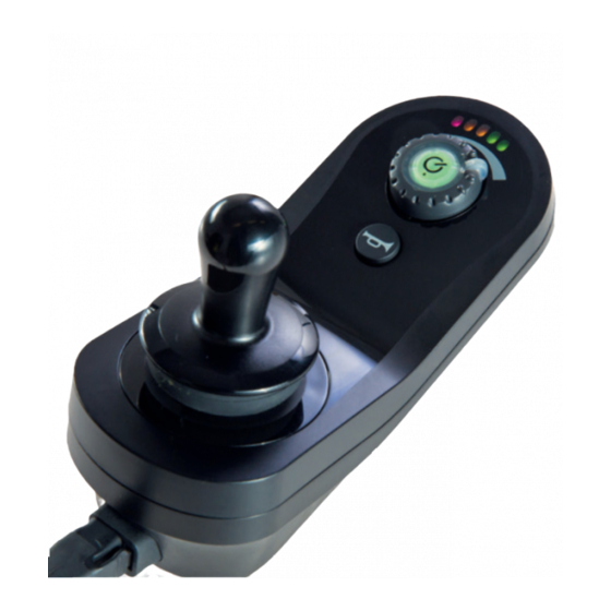
Page 9: User Interface Dlx-Rem110
Components 3.2 User interface DLX-REM110 D Horn E Joystick 3.3 User interface DLX-REM211 A ON/OFF button/Status indicator B Battery gauge A ON/OFF button/Status indicator C Speed dial B Battery gauge C Speed dial 1602969-F... -
Page 10: User Interface Dlx-Rem216
Invacare® LiNX 3.4 User interface DLX-REM216 D Connectivity indicator E Seating function selector F Drive/actuator status G Horn H Joystick I Drive function indicator J Drive function selector A ON/OFF button/Status indicator B Battery gauge C Speed dial D Connectivity indicator... -
Page 11: User Interface Dlx-Rem050 (Only As Attendant Control Unit)
Components 3.5 User interface DLX-REM050 (only as G Lights and direction indicator right attendant control unit) H Horn I Joystick J Hazard lights and direction indicator left K Drive function indicator L Drive function selector A ON/OFF button/Status indicator B Speed dial C Horn D Battery gauge E Joystick... -
Page 12: The Status Indicator
Invacare® LiNX 3.6 The status indicator Decreased driving range The status indicator is located inside the ON/OFF button. Red and one amber LED on. When the LiNX remote is not powered up, the status Consider charging batteries. indicator is not lit. - Page 13 Components Recommendation to read the This is the WEEE symbol instruction manual before (Waste Electrical and using the module. Electronic Equipment Directive). READ INSTALLATION MANUAL BEFORE USE This product has been B IPx4 This is the enclosure's ingress supplied from an protection rating.
- Page 14 Invacare® LiNX Serial number and date of manufacture Product label containing: The serial number on a Dynamic Controls product provides • Dynamic Controls' both the date of manufacture as well as a unique serial 'dynamic' logo number for the particular module.
-
Page 15: Setup
Setup function, and then activate a different output when the 4 Setup system is in another state or function. For example, a buddy button that is used to stop a wheelchair when driving can 4.1 General information on setup also be used to extend a seating motion when in a seating The tasks described in this chapter are intended to be function. -
Page 16: Connecting The Remote
Invacare® LiNX Adequate strain relief must be provided for all cables, and be minimized wherever possible, to extend service life and the mechanical limits of the cables and looms must not be minimize the risk of accidental damage. exceeded. Risk of damage to bus cable... - Page 17 Setup Risk of damage to the remote The remote plug and connector socket fit together in one way only. – Do not force them together. 1. Lightly push to connect the plug of the remote cable and the connector socket. The plug must lock in place with an audible click.
-
Page 18: Usage
Invacare® LiNX Powering up the remote 5 Usage 1. Press ON/OFF button A. 5.1 Operating the remote If there is no fault with the system, the status indicator lights up green and the battery gauge displays the Your wheelchair always powers up in drive function 1 and current battery status. -
Page 19: Controlling The Maximum Speed
Usage The joystick can also be used to wake up the system when in sleep mode, if this parameter has been enabled by the provider. Refer to 5.5 The sleep mode, page 21. 5.1.2 Controlling the maximum speed The speed dial allows you to limit the maximum speed of the mobility device (that is the speed when the joystick is fully deflected) to suit your preferences and environment. -
Page 20: The Horn
Invacare® LiNX 5.3 The horn Locking the remote Press the horn button A to sound the horn. The horn sounds for as long as the horn button is pressed. The horn button is also used for unlocking a locked system. -
Page 21: The Sleep Mode
Usage Unlocking the remote green (far left, middle and far right) until either the system is powered off, unlocked or the Sequence Timeout is reached. If an DLX-REM050 is used as attendant control unit, it is locked or unlocked, too. You can also lock and unlock the system DLX-REM050. -
Page 22: Activate Seating Function
Invacare® LiNX 5.6.1 Activate seating function Powered seat tilt Powered recline Seat lifter 1. Press Seating function key A. • The wheelchair changes to seating function and the Left or center-mount powered elevating legrest Drive/actuator status display C lights up amber. -
Page 23: The 10 Way Switch Module
5.6.4 Speed reduction and seating function inhibits 5.6.3 The 10 way switch module The mentioned speed reduction and seating function inhibits do not apply to all Invacare wheelchair models. Speed reduction If the lifter has been adjusted above a certain point, the drive electronics considerably reduces the speed of the wheelchair. -
Page 24: Activating The Drive Function
Invacare® LiNX 5.7 Activating the drive function symbol start pulsing. These two symbols remain pulsing while driving to show the speed reduction until speed reduction has been deactivated again. Seating function inhibits • Tilt limit The maximum tilt limit switch is a function to prevent... -
Page 25: Audible Cues
For example, no audible cue is played when the choose between three different drive functions, system moves into sleep mode. that are configured by Invacare and can be customized to your needs and requests by the Event cues comprise two or three notes and are played on provider. - Page 26 Invacare® LiNX Navigation Cues Function = Drive 1 Identifier = None Navigation cues are played when activating a function. Navigation Type Navigation Cue Sound Condition Fig. 5-1 Drive function Played when Function = Drive 2 Identifier = 1 activating a drive function.
-
Page 27: Operating The Lights
Usage Profile Index 1. profile index (e.g. one note to indicate first profile) 2. navigation cue (e.g. drive function) Profile Index 3. function identifier (e.g. function identifier is set to 2) 5.9 Operating the lights Profile 1 If you drive outside, turn on the lights under bad Fig. -
Page 28: Operating The Hazard Lights
Invacare® LiNX 5.10 Operating the hazard lights Direction indicator left 1. Press Hazard lights button A for more than three seconds. Left direction indicator is turned on. 2. To turn off direction indicator, short press Hazard lights button again. Direction indicator right 1. - Page 29 Usage Please cycle the power prior to charging if wheelchair Battery charge state 1 has not been used within 24 hours. This will ensure the enhanced battery gauge registers the charge to Red LED on. give an accurate reading during use of wheelchair. If it is not powered up, the battery gauge does not Battery charge state 2 indicate the charging state.
-
Page 30: Battery Alarms
Before using the attendant control unit for the first time, you should familiarize well with its operation. 1. Disconnect battery charger. Invacare recommends to test the behavior of the Low voltage warning attendant control unit without an occupant to avoid injury. - Page 31 Usage respond to any commands except for its ON/OFF button, Remote-in-charge indication which can always turn off the system. Remote-in-charge Remote-not-in-charge Powering up All indicators, including the The battery gauge is Either of the remotes can power up the system with their battery gauge displays as switched off and all other own ON/OFF button.
-
Page 32: Troubleshooting
Invacare® LiNX The actions listed are not in any particular order and 6 Troubleshooting are suggestions only. The intention is that one of the suggestions may help you clear the problem. If in doubt, 6.1 Fault diagnosis contact your provider. -
Page 33: Oon ("Out Of Neutral")
Troubleshooting Flash Fault description Possible action Flash Fault description Possible action code code Left magnetic • Check cables and Right magnetic • Check cables and brake fault connectors. brake fault connectors. • Check left magnetic • Check right magnetic brake is engaged. brake is engaged. -
Page 34: Drive Inhibit Indication
Invacare® LiNX • when the system comes out of an inhibit or drive off) to alert the user. In this state the seating motions do lock-out. not operate. If the switches are deactivated, the warning clears and the seating motions operate normally. -
Page 35: Cut-Off Voltage
Troubleshooting 6.4 Cut-off voltage When the battery voltage decreases below the battery cut-off voltage: • the status indicator flashes red (Flash code 2, refer to 6.1.1 Fault codes and diagnosis codes, page 32), • the red LED on the battery gauge flashes, •... -
Page 36: Technical Data
Invacare® LiNX 7 Technical Data 7.1 Technical specifications Mechanical specifications Permissible operating, storage and humidity conditions • –25° ... +50 °C Temperature range for operation according to ISO 7176–9: Recommended storage temperature: • 15 °C Temperature range for storage according to ISO 7176–9: •... - Page 37 Technical Data Electrical specifications Parameter Max. Min. Nominal Units • • • • Operating voltage (Vbatt) • • mA at 24V Idle current Quiescent current • 0.23 • mA at 24V (power off) 1602969-F...
- Page 38 Notes...
- Page 39 www.invacarelinx.com...
- Page 40 Invacare Sales Companies Australia: Canada: Ireland: New Zealand: Invacare Australia Pty. Ltd. Invacare Canada L.P. Invacare Ireland Ltd, Invacare New Zealand Ltd 1 Lenton Place, North Rocks NSW 570 Matheson Blvd East, Unit 8 Unit 5 Seatown Business Campus 4 Westfield Place, Mt Wellington 1060 2151 CDN Mississauga, On.