GEM 533 eSyStep Operating Instructions Manual
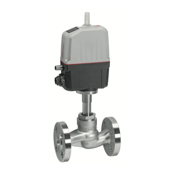
Motorized globe valve
Hide thumbs
Also See for 533 eSyStep:
- Operating instructions manual (55 pages) ,
- Operating instructions manual (61 pages) ,
- Operating instructions manual (64 pages)

Related Manuals for GEM 533 eSyStep


Summary of Contents for GEM 533 eSyStep
- Page 1 GEMÜ 533 eSyStep Positioner (Code S0) Motorized globe valve Operating instructions further information webcode: GW-533...
- Page 2 All rights including copyrights or industrial property rights are expressly reserved. Keep the document for future reference. © GEMÜ Gebr. Müller Apparatebau GmbH & Co. KG 24.10.2019 GEMÜ 533 2 / 52 www.gemu-group.com Positioner (Code S0)
-
Page 3: Table Of Contents
LED symbols ............Definition of terms ..........Warning notes ............ 2 Safety information ............ 3 Product description ........... 4 GEMÜ CONEXO ............5 Correct use ..............6 Order data ..............7 Technical data ............8 Dimensions ............... 13 9 Manufacturer's information ........16 Delivery ............... -
Page 4: General Information
1.4 Definition of terms Working medium The medium that flows through the GEMÜ product. Diaphragm size Uniform seat size of GEMÜ diaphragm valves for different nominal sizes. 1.5 Warning notes Wherever possible, warning notes are organised according to the following scheme:... -
Page 5: Safety Information
14. Do not carry out any maintenance work and repairs not described in this document without consulting the manu- facturer first. In cases of uncertainty: 15. Consult the nearest GEMÜ sales office. www.gemu-group.com 5 / 52 GEMÜ 533 Positioner (Code S0) -
Page 6: Gemü Conexo
3.2.1 Status LEDs dicator. 4 GEMÜ CONEXO Order with CONEXO GEMÜ CONEXO must be ordered separately with the ordering option "CONEXO" (see order data). For electronic identification purposes, each replaceable com- ponent contained in the product is equipped with an RFID chip (1). -
Page 7: Order Data
(NO) 9 Regulating cone Code without Please find the number of the optional regulating R…. cone (R-No.) for the linear or equal-percentage modified regulating cone in the Kv value table. 7 / 52 www.gemu-group.com GEMÜ 533 Positioner (Code S0) - Page 8 Kv value table. 10 Actuator version Actuator size 0 11 Type of design Without 12 CONEXO Integrated RFID chip for electronic identification and traceability 8 / 52 GEMÜ 533 www.gemu-group.com Positioner (Code S0)
-
Page 9: Technical Data
Code 48: Flange JIS 20K, face-to-face dimension FTF EN 558 series 10, ASME/ANSI B16.10 table 1, column 16, DN 50 drilled to JIS 10K 2) Valve body material Code 37: 1.4408, investment casting Code 90: EN-GJS-400-18-LT (GGG 40.3) 9 / 52 www.gemu-group.com GEMÜ 533 Positioner (Code S0) - Page 10 DIN EN 61000-6-4 (Sep. 2011) Interference emission class: Class A Interference emission group: Group 1 7.5 Mechanical data Protection class: IP 65 acc. to EN 60529 Weight: Actuator 950 g Body DN 15: 2.2 kg 10 / 52 GEMÜ 533 www.gemu-group.com Positioner (Code S0)
- Page 11 Function selectable via IO-Link (see table Overview of available functions – Input and output sig- nals) Input voltage: 24 V DC Logic level "1": > 15.3 V DC Logic level "0": < 5.8 V DC Input current: typically < 0.5 mA 11 / 52 www.gemu-group.com GEMÜ 533 Positioner (Code S0)
- Page 12 Function selectable via IO-Link (see table Overview of available functions – Input and output sig- nals) Type of contact: Push-Pull Switching voltage: Power supply Uv Switching current: ≤ 140 mA Short-circuit proof: 7.7.5 Communication Interface: IO-Link Function: Parameterization/process data Transmission rate: 38.4 kBaud 12 / 52 GEMÜ 533 www.gemu-group.com Positioner (Code S0)
-
Page 13: Dimensions
SW 1 DN SW 197.7 33.2 162.7 59.4 62.5 133.5 316.8 281.8 197.7 33.2 162.7 59.4 62.5 133.5 324.3 289.3 197.7 33.2 162.7 59.4 62.5 133.5 334.8 299.8 Dimensions in mm 13 / 52 www.gemu-group.com GEMÜ 533 Positioner (Code S0) - Page 14 Code 48: Flange JIS 20K, face-to-face dimension FTF EN 558 series 10, ASME/ANSI B16.10 table 1, column 16, DN 50 drilled to JIS 10K 2) Valve body material Code 37: 1.4408, investment casting 14 / 52 GEMÜ 533 www.gemu-group.com Positioner (Code S0)
- Page 15 Code 39: Flange ANSI Class 125/150 RF, face-to-face dimension FTF EN 558 series 1, ISO 5752, basic series 1 2) Valve body material Code 37: 1.4408, investment casting Code 90: EN-GJS-400-18-LT (GGG 40.3) 15 / 52 www.gemu-group.com GEMÜ 533 Positioner (Code S0)
-
Page 16: Manufacturer's Information
▶ Damage to the GEMÜ product. 4. Do not store solvents, chemicals, acids, fuels or similar Provide precautionary measures against exceeding the ● fluids in the same room as GEMÜ products and their maximum permitted pressures caused by pressure spare parts. surges (water hammer). -
Page 17: Installation Position
The installation position of the product is optional. 10.3 Installation with flanged connection Fig. 1: Flanged connection NOTICE Sealing material ▶ The sealing material is not included in the scope of deliv- ery. Only use appropriate sealing material. ● www.gemu-group.com 17 / 52 GEMÜ 533 Positioner (Code S0) -
Page 18: Electrical Connection
Connection X2 (only for control module code S0) 5-pin M12 plug, A-coded Signal name I+/U+, set value input I-/U-, set value input I+/U+, actual value output I-/U-, actual value output n. c. 18 / 52 GEMÜ 533 www.gemu-group.com Positioner (Code S0) - Page 19 0 – 20 mA 0 – 10 V Analogue output 4 – 20 mA 4 – 20 mA 4 – 20 mA 4 – 20 mA 0 – 20 mA 0 – 10 V 19 / 52 www.gemu-group.com GEMÜ 533 Positioner (Code S0)
-
Page 20: Specific Data Io-Link (Pin 6)
12.1 Operation on IO-Link 12.1.1 Operation on PLC as a 24 V device The motorized actuator GEMÜ eSyStep can be operated directly in a PLC control unit without limitations. Technical data of the product and of PLC must be complied with. - Page 21 During IO-Link operation, pin 6 cannot be evaluated by the PLC control unit as an output signal. Item Name eSyStep PLC with supply voltage USB IO-Link Master USB interface Mains plug – laptop 21 / 52 www.gemu-group.com GEMÜ 533 Positioner (Code S0)
- Page 22 ● Connect pin 4 (CQ) IO-Link master with pin 6 of the product. Do not connect (pin 3) L- IO-Link master. (L-) Item Name eSyStep B1 and B2 Supply voltages USB IO-Link Master 22 / 52 GEMÜ 533 www.gemu-group.com Positioner (Code S0)
-
Page 23: Process Data
1 → process valve in Close position Indication of operating mode 0 → normal operation 1 → initialization mode Position feedback 8 to 23 Position of the valve within the range of 0 to 1000 23 / 52 www.gemu-group.com GEMÜ 533 Positioner (Code S0) -
Page 24: Parameter Overview
0x4C Function digital input/ Configure digital in- 0 → Output Open output puts/outputs 1 → Output Close 2 → Output Error 3 → Output Error & Warning 4 → Input Init 24 / 52 GEMÜ 533 www.gemu-group.com Positioner (Code S0) - Page 25 0 to 4095 tiometer Supply Voltage Analogue value supply 0 to 4095 voltage Temperature Analogue value tem- 0 to 4095 perature sensor Set value input Analogue value signal 0 to 4095 input 25 / 52 www.gemu-group.com GEMÜ 533 Positioner (Code S0)
- Page 26 (0.0% to Max) Analog Out Max Determine maximum 1000 Min to 1000 signal output (Min to 100%) 0xBC Init Time Set debounce time for 50 to 5000 initialization start (50 to 5000 ms) 26 / 52 GEMÜ 533 www.gemu-group.com Positioner (Code S0)
-
Page 27: Parameter
Type Values Index Rights 0x03 1 byte Data Storage UIntegerT8 1 byte State Property UIntegerT8 4 bytes Data Storage UIntegerT32 Size 4 bytes Parameter Checksum UIntegerT32 41 bytes Index List OctetStringT 27 / 52 www.gemu-group.com GEMÜ 533 Positioner (Code S0) - Page 28 The serial number consists of an 8-digit completion confirmation number, a forward slash and a 4-digit index. Index Sub- Off- Access Length Parameter Type Values Index Rights 0x15 13 bytes Serial Number StringT "XXXXXXXX/YYYY" 28 / 52 GEMÜ 533 www.gemu-group.com Positioner (Code S0)
- Page 29 The actuator size can be read out in numbers with the Actuator Size parameter. Sub- Off- Access Length Parameter Type Default Values Rights 0x40 2 bits Actuator Size uint: 8 0 → size 0 1 → size 1 2 → size 2 29 / 52 www.gemu-group.com GEMÜ 533 Positioner (Code S0)
- Page 30 If there is no signal, the device moves into the safety position. The safety position is defined by the parameter Error Action (index 0x4F (see "Error Action'"). (Init) Input can be used as an initialization input. 30 / 52 GEMÜ 533 www.gemu-group.com Positioner (Code S0)
- Page 31 Close depends on the setting of the parameter Position Feedback (index 0x51 (see “Position feedback“, page 34)) and a correct initialization. (Output Error) Only output error detection. (Output Error & Warning) Output error and warnings. 31 / 52 www.gemu-group.com GEMÜ 533 Positioner (Code S0)
- Page 32 (Open) Actuator moves to the OPEN position in case of an error. (Close) Actuator moves to the CLOSED position in case of an error. Error Time 1 to 1000 Determine delay time between error detection and error message. 32 / 52 GEMÜ 533 www.gemu-group.com Positioner (Code S0)
- Page 33 (OPEN/CLOSE) The actuator is in OPEN/CLOSE mode. IO-Link Process (Disabled) Use of IO-Link process data (see “Process data“, page 23) is Data deactivated. (Enabled) Use of IO-Link process data (see “Process data“, page 23) is activated. 33 / 52 www.gemu-group.com GEMÜ 533 Positioner (Code S0)
- Page 34 Read out the OPEN position analogue value. Close 0 to 4092 Read out the CLOSED position analogue value. Stroke 0 to 4092 Read out the analogue value for stroke (difference between OPEN and CLOSED). 34 / 52 GEMÜ 533 www.gemu-group.com Positioner (Code S0)
- Page 35 Read out current analogue value of the supply voltage. Temperature 0 to 4095 Read out current analogue value of the temperature sensor. Set value input 0 to 4095 Read out current analogue value of the set value. 35 / 52 www.gemu-group.com GEMÜ 533 Positioner (Code S0)
- Page 36 0 to 100 Set the derivative action time T1 (always available delay constant). time T1 (0 to 100 s) Dead zone 1 to 250 Set the dead zone (hysteresis). (0.1 to 25.0%) 36 / 52 GEMÜ 533 www.gemu-group.com Positioner (Code S0)
- Page 37 Set the start of the set value range. (0.0 to Split End – 10.0%) Split End Split Start + 100 to Set the end of the set value range. 1000 (Split Start + 10.0% to 100.0%) 37 / 52 www.gemu-group.com GEMÜ 533 Positioner (Code S0)
- Page 38 U Max W 100 to 110 Determine maximum value of the voltage input. If the set value is exceeded, the (10.0 to 11.0 V) message "Set value too high" is issued. 38 / 52 GEMÜ 533 www.gemu-group.com Positioner (Code S0)
- Page 39 (50 to 5000 ms) Description of parameter values Parameter Values Description Debounce time ini- 50 to 5000 Determine time from applying the signal to starting initialization. tialization input (50 to 5000 ms) 39 / 52 www.gemu-group.com GEMÜ 533 Positioner (Code S0)
- Page 40 (0.0 to 100%) Force Init 0 to 1000 Set the force during initialization. (0.0 to 100%) Force settings Actuator size Setting parameter Force in Newton AS 0 0 (0%) 500 (50%) 1000 (100%) 40 / 52 GEMÜ 533 www.gemu-group.com Positioner (Code S0)
-
Page 41: Events
Description Possible cause Troubleshooting Device Hardware Fault The event occurs when a Fault in valve position – Contact GEMÜ Support 0x5000 hardware fault is detected. detection. Parameter can no longer be read when switching the device on. Motor Unable To Move... - Page 42 12 Specific data IO-Link (pin 6) Event Description Possible cause Troubleshooting Actuator has been fitted on the valve incorrectly (stroke of the valve in the incorrect area). 42 / 52 GEMÜ 533 www.gemu-group.com Positioner (Code S0)
-
Page 43: Operation
2. Operate the manual override 3 with the hexagon socket 5. The end positions are set. (WAF3). ð Turn clockwise to close the valve. ð Turn anticlockwise to open the valve. www.gemu-group.com 43 / 52 GEMÜ 533 Positioner (Code S0) -
Page 44: Inspection And Maintenance
5. Clean all parts of contamination (do not damage parts 5. Depressurize the plant or plant component. during cleaning). 6. Actuate GEMÜ products which are always in the same 6. Check parts for potential damage, replace if necessary position four times a year. -
Page 45: Replacing The Seals
DN 20 100 Nm DN 25 120 Nm 5. Move the actuator A to the closed position. 6. With the valve fully assembled, check the function and tightness. 7. Carry out initialisation. www.gemu-group.com 45 / 52 GEMÜ 533 Positioner (Code S0) -
Page 46: Troubleshooting
Emergency power operation, OPEN position Emergency power operation, CLOSED position Emergency power operation, position unknown Set value too small Set value too high Maintenance required, OPEN position Maintenance required, CLOSED position Maintenance required, position unknown 46 / 52 GEMÜ 533 www.gemu-group.com Positioner (Code S0) - Page 47 Valve body / actuator damaged Replace valve body/actuator Body of the GEMÜ product is leaking Body of the GEMÜ product is faulty or Check the body of the GEMÜ product for corroded potential damage, replace body if...
-
Page 48: Removal From Piping
3. Disassemble the product. Observe warning notes and goods can be processed only when this note is completed. If safety information. no return delivery note is included with the product, GEMÜ cannot process credits or repair work but will dispose of the 17 Disposal goods at the operator's expense. -
Page 49: Declaration Of Incorporation According To 2006/42/ Ec (Machinery Directive)
19 Declaration of Incorporation according to 2006/42/EC (Machinery Directive) Declaration of Incorporation according to the EC Machinery Directive 2006/42/EC, Annex II, 1.B for partly completed machinery GEMÜ Gebr. Müller Apparatebau GmbH & Co. KG Fritz-Müller-Straße 6-8 74653 Ingelfingen-Criesbach, Germany declare that the following product Make: GEMÜ... -
Page 50: Declaration Of Conformity According To 2014/68/Eu (Pressure Equipment Directive)
AD 2000 Note for products with a nominal size ≤ DN 25: The products are developed and produced according to GEMÜ process instructions and quality standards which comply with the requirements of ISO 9001 and ISO 14001. According to Article 4, Paragraph 3 of the Pressure Equipment Directive 2014/68/EU these products must not be identified by a CE-label. -
Page 51: Declaration Of Conformity According To 2014/30/Eu (Emc Directive)
21 Declaration of conformity according to 2014/30/EU (EMC Directive) EU Declaration of Conformity according to 2014/30/EU (EMC Directive) GEMÜ Gebr. Müller Apparatebau GmbH & Co. KG Fritz-Müller-Straße 6-8 74653 Ingelfingen-Criesbach, Germany declare that the product listed below complies with the safety requirements of the EMC Directive 2014/30/EU. - Page 52 GEMÜ Gebr. Müller Apparatebau GmbH & Co. KG Subject to alteration Fritz-Müller-Straße 6-8, 74653 Ingelfingen-Criesbach, Germany 10.2019 | 88668387 Phone +49 (0)7940 123-0 · info@gemue.de *88668387* www.gemu-group.com...