GEM 1434 mPos Installation, Operating And Maintenance Instructions
Intelligent positioner for pneumatically operated linear actuators
Hide thumbs
Also See for 1434 mPos:
- Installation, operating and maintenance instructions (25 pages) ,
- Operating instructions manual (32 pages) ,
- Manual (20 pages)
Table of Contents
Advertisement
Available languages
Available languages
Quick Links
Intelligenter Stellungsregler
for pneumatically operated linear actuators
ORIGINAL EINBAU- UND MONTAGEANLEITUNG
DE
INSTALLATION, OPERATING AND
GB
MAINTENANCE INSTRUCTIONS
Stand 07.10.16
Ab Version 1.1.2.1
Status 07th October 2016
From version 1.1.2.1
für fremdgesteuerte Linearantriebe
Intelligent positioner
1434 Pos
1434 µPos
Advertisement
Chapters
Table of Contents

Related Manuals for GEM 1434 mPos


Summary of Contents for GEM 1434 mPos
- Page 1 1434 Pos Intelligenter Stellungsregler für fremdgesteuerte Linearantriebe Intelligent positioner for pneumatically operated linear actuators ORIGINAL EINBAU- UND MONTAGEANLEITUNG INSTALLATION, OPERATING AND MAINTENANCE INSTRUCTIONS Stand 07.10.16 Ab Version 1.1.2.1 Status 07th October 2016 From version 1.1.2.1 1434 µPos...
-
Page 2: Table Of Contents
Lieferung oder gewerbliche Schutzrechte Funktion werden ausdrücklich vorbehalten. Mechanischer Anbau Komplettierung des Weggebers Der GEMÜ 1434 Pos ist vom Betreiber Anbau des Stellungsreglers bestimmungsgemäß zu gebrauchen. Anbau des externen Weggebers Alle Angaben dieser Einbau- und Montageanleitung in Hinsicht auf (nur bei Variante mit externem... -
Page 3: Hinweise Zur Sicherheit
Geräte sicher. Beachten Sie auch die Einhaltung der elektrischen Daten. Die Nichtbeachtung der Sicherheitshinweise kann sowohl eine Gefährdung für Personen als auch für die Umwelt und den GEMÜ 1434 Pos zur Folge haben. Die Nichtbeachtung der Sicherheitshinweise kann zum Verlust jeglicher Schadensersatzansprüche führen. -
Page 4: Hinweise Für Den Einsatz In
Schraubenziehers IP 65 nicht ausreichend. entfernen. Die folgenden Informationen geben eine Hilfestellung bei der Montage und dem Betrieb des GEMÜ 1434 Pos in feuchter Umgebung: Verlegung von Kabeln und Rohren so vornehmen, dass Kondensat oder Regenwasser, welches an den Rohren / Leitungen hängt, nicht in... -
Page 5: Einbaulage
6. Pneumatikverschraubung in Wartung und Service Gewindeadapter einschrauben und Der GEMÜ 1434 Pos unterliegt bei einem vorsichtig festziehen. Einbau und Einsatz gemäß dieser Einbau- und Montageanleitung und des Datenblattes keiner Wartung / Service. Helfen Sie mit das Produkt weiter zu entwickeln und leiten Sie abweichendes Verhalten gegenüber der Beschreibung... -
Page 6: Mechanischer Anbau
Mechanischer Anbau Komplettierung des Weggebers VORSICHT Vorgespannte Feder! ® Beschädigung des Gerätes. Spindel festhalten und Betätigungs- spindel handfest anziehen. Feder langsam entspannen. VORSICHT Eine Beschädigung der Spindeloberfl äche kann zum Ausfall des Weggebers führen! Der Weggeber wird mit einem Anbausatz 1434S01Z... -
Page 7: Anbau Des Stellungsreglers
Anbau des Stellungsreglers Bei GEMÜ 650 beiliegend (O-Ring C nur bei Steuerfunktion 2 und 3): Druckscheibe B O-Ring C Ventil mit Stellungsregler Weggeber komplettieren (siehe Kapitel 3.1 „Komplettierung des Weggebers“). Stellungsregler 1 auf Antrieb 3 bzw. Adapter E aufsetzen und mit einem geeigneten Gabelschlüssel SW 20 / SW... -
Page 8: Anbau Des Externen Weggebers (Nur Bei Variante Mit Externem Anbau)
Ventil mit externem Weggeber Stellungsregler 1 an geeigneter Stelle befestigen. Hierzu kann der Befestigungs- winkel GEMÜ 1446 00 ZMP verwendet werden (dieser muss separat bestellt werden). Weggeber komplettieren (siehe Kapitel 3.1 „Komplettierung des Weggebers“). Weggeber 4 auf Antrieb 3 aufsetzen und mit einem geeigneten Gabelschlüssel... -
Page 9: Pneumatische Anschlüsse
Elektrische Anschlüsse um max. 360° maximal 360° verdrehen. Initialisierung und Inbetriebnahme Wird der GEMÜ 1434 Pos ab Werk komplett an ein Ventil montiert geliefert, so ist dieser schon werkseitig voreingestellt (bei einem Steuerdruck von 5,5 - 6 bar ohne Betriebsdruck) und somit betriebsbereit. -
Page 10: Elektrischer Und Pneumatischer Anschluss
1. Initialisierungsspannung 24 V DC an Pin 5 anschließen und aktivieren (t > 100ms). Symbol Symbol +4-20mA OPEN CLOSED ERROR POWER 2. Nach Beenden der Initialisierung wird das Prozessventil in die Position gemäß +24V DC Sollwertsignal positioniert. Sollwert min Symbol Symbol OPEN CLOSED ERROR POWER... -
Page 11: Anzeigeelemente
Anzeigeelemente OPEN ERROR CLOSED POWER Bezeichnung Farbe OPEN gelb ERROR CLOSED orange POWER gelb LED 1 LED 2 LED 3 LED 4 Bedeutung Fehlernummer OPEN ERROR CLOSED POWER Position erreicht Ventil in Endlage AUF Ventil in Endlage ZU Ventil fährt in Richtung AUF Ventil fährt in Richtung ZU Regler in Initialisierungsphase Sollwert >... -
Page 12: Fehlermeldungen
Nur wenn diese Erklärung achten. vollständig ausgefüllt ist, wird die Rücksendung bearbeitet! Rücksendung Stellungsregler reinigen. Hinweise Rücksendeerklärung bei GEMÜ anfordern. Hinweis zur Mitarbeiterschulung: Rücksendung nur mit vollständig Zur Mitarbeiterschulung nehmen ausgefüllter Rücksendeerklärung. Sie bitte über die Adresse auf der letzten Seite Kontakt auf. -
Page 13: Maße
Maße Externer Anbau [mm] Direkter Anbau [mm] 13,6 SW24 M20x1,5 SW24 13,6 SW27 SW 20 bei Anbausatz M12 x1, x = 9 mm SW 24 bei Anbausatz M16 x1, x = 11 mm Befestigungswinkel [mm] 1434 µPos 13 / 32... -
Page 14: Technische Daten
1 / 3 k Mindesthub ≥ 8 % der Weggeberlänge Der Stellungsregler GEMÜ 1434 Pos erkennt automatisch während der Initialisierung die Steuerfunktion des Ventils: Federkraft geöffnet (NO) oder Federkraft geschlossen (NC) Bei Signalvorgabe 0/4 mA oder 0 V ist die Stellung des Ventils geschlossen. -
Page 15: Bestelldaten
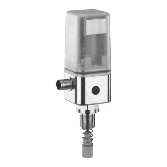
Steuerfunktion. Weggeberlänge vom Anbausatz beachten. Ein Fitting und Pneumatikschlauch für das Ventill, liegt jedem Regler mit Anschluss Pneumatisch (Code 2 und 3) bei. Die Abbildung auf Seite 1 zeigt den Stellungsregler GEMÜ 1434 Pos mit Anbausatz. Benötigte Teile für direkten Anbau Benötigte Teile für externen Anbau... -
Page 16: Eu-Konformitätserklärung
EU-Konformitätserklärung EU-Konformitätserklärung Wir, die Firma GEMÜ Gebr. Müller Apparatebau GmbH & Co. KG Fritz-Müller-Straße 6-8 D-74653 Ingelfingen erklären, dass das unten aufgeführte Produkt der folgenden Richtlinie entspricht: • EMV-Richtlinie 2014/30/EU Produkt: GEMÜ 1434 Joachim Brien Leiter Bereich Technik Ingelfingen-Criesbach, September 2016 1434 µPos... - Page 17 Technical data maintenance instructions are only applicable Order data in Germany. If the GEMÜ 1434 Pos is EU Declaration of Conformity used in other countries, the local applicable regulations must be observed. When dealing with harmonised European norms, standards and guidelines, these apply within the Single European Market.
-
Page 18: Safety Notes
Correct use version. The GEMÜ 1434 Pos is suitable for use The safety information does not take into in specific fixed plant as defined in the data account unexpected incidents and events sheet. which may occur during installation,... -
Page 19: Information On Use In Damp Conditions
1 x for conversion to protection class IP 67 2x and for installation with piped air outlet.. The housing on the GEMÜ 1434 Pos is protected against the penetration of 5. Screw the threaded adapter with the O-ring liquid as standard. In order to meet special... -
Page 20: Installation Position
When installed and used in accordance with these installation, operating and maintenance instructions and the data sheet, the GEMÜ 1434 Pos is not subject to any service and maintenance. Contribute to further development of the product and pass on any behaviour that deviates from the description to your nearest GEMÜ... -
Page 21: Mechanical Mounting
Mechanical mounting Assembling the travel sensor CAUTION Pretensioned spring ® Damage to the device. Slowly release the tension in the spring. Hold the spindle and tighten the operating bush hand tight. CAUTION Damage to the spindle surface may lead to failure of the travel sensor! The travel sensor is assembled using a 1434S01Z... -
Page 22: Mounting The Positioner
Mounting the positioner Enclosed for GEMÜ 650 (O-ring C only for control functions 2 and 3): Pressure disc B O-ring C Valve with positioner Assemble the travel sensor (see chapter 3.1 “Assembling the travel sensor”). Place the positioner 1 on actuator 3 or adapter E and fi... -
Page 23: Mounting The External Travel Sensor (Only For Version With Remote Mounting)
Valve with external travel sensor Fix positioner 1 at a suitable location. The GEMÜ 1446 00 ZMP mounting bracket (to be ordered separately) can be used to do this. -
Page 24: Pneumatic Connections
360° max. 360°. Initialisation and commissioning If the GEMÜ 1434 Pos is delivered fully mounted to a valve ex works, it is already preset at the factory (at a control pressure of 5.5 – 6 bar without operating pressure) and is therefore ready for operation. -
Page 25: Electrical And Pneumatic Connection
Electrical and pneumatic 2. Deactivate initialisation power supply. connection Symbol Symbol OPEN CLOSED 1. Activate pneumatic control air supply ERROR POWER (max. 8/10 bar). +24V DC Symbol Flashes fast Flashes slowly 2. Switch on 24 V power supply. 3. Automatic initialisation is carried out. POWER LED on. -
Page 26: Display Elements
Display elements OPEN ERROR CLOSED POWER Designation Colour OPEN Yellow ERROR CLOSED Orange POWER Yellow LED 1 LED 2 LED 3 LED 4 Meaning Error number OPEN ERROR CLOSED POWER Position reached Valve in OPEN end position Valve in CLOSED end position Valve moves in OPEN direction Valve moves in CLOSED direction Positioner in initialisation phase... -
Page 27: Error Messages
Returns must be made with a completed Should there be any doubts or return delivery note. misunderstandings in the preceding text, If not completed, GEMÜ cannot process the German version of this document is the credits or authoritative document! repair work but will dispose of the goods at the operator’s expense. -
Page 28: Dimensions
Dimensions Remote mounting [mm] Direct mounting [mm] 13,6 SW24 M20x1,5 SW24 13,6 SW27 SW 20 for mounting kit M12 x1, x = 9 mm SW 24 for mounting kit M16 x1, x = 11 mm Mounting bracket [mm] 1434 µPos 28 / 32... -
Page 29: Technical Data
Technical data General information Electrical data Protection class to EN 60529 IP 65 / IP 67 ¹⁾ Power supply Weight 220 g Power supply = 18...30 V DC Dimensions L x W x H See dimensional drawing ≤ 4 W (up to 24 V DC) Power consumption Mounting position Optional... -
Page 30: Order Data
Observe mounting kit travel length. A fitting and pneumatic tubing for the valve is included with each positioner with pneumatic connection (code 2 and 3). The photo on page 1 shows the GEMÜ 1434 Pos positioner with mounting kit. Required parts for direct mounting Required parts for remote mounting GEMÜ... -
Page 31: Eu Declaration Of Conformity
EU Declaration of Conformity EU Declaration of Conformity Hereby we, GEMÜ Gebr. Müller Apparatebau GmbH & Co. KG Fritz-Müller-Straße 6-8 D-74653 Ingelfingen declare that the product listed below complies with the following directive: • EMC Directive 2014/30/EU Product: GEMÜ 1434... - Page 32 GEMÜ Gebr. Müller Apparatebau GmbH & Co. KG · Fritz-Müller-Str. 6-8 · D-74653 Ingelfi ngen-Criesbach Telefon +49(0)7940/123-0 · Telefax +49(0)7940/123-192 · info@gemue.de · www.gemu-group.com...