Mitsubishi Electric FR-V500 Series Instruction Manual
Vector inverter
Hide thumbs
Also See for FR-V500 Series:
- Instruction manual (232 pages) ,
- Instruction manual (112 pages)
Table of Contents
Advertisement
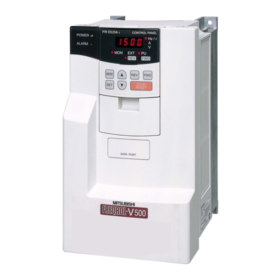
VECTOR INVERTER
FR-V
500
INSTRUCTION MANUAL (BASIC)
FR-V520-1.5K to 55K
FR-V540-1.5K to 55K
Thank you for choosing this Mitsubishi Vector Inverter.
If this is the first time for you to use the FR-V500 series, please read through this Instruction Manual (basic)
carefully to use the inverter safely.
When you are going to use the inverter for higher-leveled applications, please request the separately available
FR-V500 Instruction Manual (detailed) [IB(NA)-0600131E] from where you purchased the inverter or a Mitsubishi
sales representative.
1
OUTLINE .................................................................................................... 1
1.1
Basic configuration and connection of peripheral devices........................................ 2
1.2
Structure ................................................................................................................... 4
INSTALLATION AND WIRING ................................................................... 6
2
2.1
Installation of the inverter ......................................................................................... 6
2.2
Connection diagram, encoder cable, PU connector ................................................. 7
2.3
Setting the motor .................................................................................................... 20
2.4
Precautions for use of the vector inverter............................................................... 22
3
RUN AND OPERATION ........................................................................... 23
3.1
Checks prior to test run .......................................................................................... 23
3.2
Basic operation (Speed setting, run, speed meter adjustment).............................. 23
3.3
Names and functions of the control panel .............................................................. 27
4
CONTROL ................................................................................................ 33
4.1
Speed control operation ......................................................................................... 33
4.2
Torque control operation ........................................................................................ 38
4.3
Position control operation ....................................................................................... 44
4.4
Control mode switchover timing ............................................................................. 45
4.5
Easy gain tuning ..................................................................................................... 47
4.6
Online auto tuning .................................................................................................. 50
4.7
(Pr. 902 to Pr. 905, Pr. 917 to Pr. 920)................................................................... 51
5
PARAMETERS ......................................................................................... 54
5.1
Function list (Simple mode parameters)................................................................. 54
5.2
Function list (Extended function parameters) ......................................................... 58
6
ERRORS AND PROTECTIVE FUNCTIONS ............................................ 74
6.1
Errors (Alarms) ....................................................................................................... 74
6.2
Correspondences between digital and actual characters....................................... 84
6.3
Resetting the inverter ............................................................................................. 84
6.4
Troubleshooting...................................................................................................... 85
7
PRECAUTIONS FOR MAINTENANCE AND INSPECTION .................... 96
7.1
Check items............................................................................................................ 96
7.2
Replacement of parts ............................................................................................. 98
7.3
Inverter replacement............................................................................................. 100
7.4
Measurement of main circuit voltages, currents and powers ............................... 101
8
SPECIFICATIONS ................................................................................. 103
8.1
Model specifications ............................................................................................. 103
8.2
Common specifications ........................................................................................ 106
8.3
Outline dimension drawings ................................................................................. 107
Contents
1
2
3
2
4
5
6
7
8
Advertisement
Chapters
Table of Contents

Related Manuals for Mitsubishi Electric FR-V500 Series


Summary of Contents for Mitsubishi Electric FR-V500 Series
-
Page 1: Table Of Contents
FR-V540-1.5K to 55K Thank you for choosing this Mitsubishi Vector Inverter. If this is the first time for you to use the FR-V500 series, please read through this Instruction Manual (basic) carefully to use the inverter safely. When you are going to use the inverter for higher-leveled applications, please request the separately available FR-V500 Instruction Manual (detailed) [IB(NA)-0600131E] from where you purchased the inverter or a Mitsubishi sales representative. - Page 2 This Instruction Manual (basic) provides handling information and precautions for use of the equipment. Please forward this Instruction Manual (basic) to the end user. This section is specifically about safety matters Do not attempt to install, operate, maintain or inspect the inverter until you have read through the Instruction Manual and appended documents carefully and can use the equipment correctly.
- Page 3 Always replace the cover and follow this Instruction Manual (basic) when operating the inverter. <Abbreviations> DU: Control panel (FR-DU04 PU: Control panel (FR-DU04 ) and parameter unit (FR-PU04V) Inverter: Mitsubishi vector inverter FR-V500 series FR-V500: Mitsubishi vector inverter FR-V500 series Pr.: Parameter number PU operation: Operation using the PU (FR-DU04 /FR-PU04V)
-
Page 4: Outline
1 OUTLINE Harmonic Suppression Guideline All models of general-purpose inverters used by specific consumers are covered by "Harmonic suppression guideline for consumers who receive high voltage or special high voltage". (For further details, refer to Instruction Manual (detailed).) Product check and name of parts Unpack the inverter and check the capacity plate on the front cover and the rating plate on the inverter side face to ensure that the product agrees with your order, an accessory L-shaped jumper (Refer to page 15 for connection method.) is included, and the inverter is intact. -
Page 5: Basic Configuration And Connection Of Peripheral Devices
Basic configuration and connection of peripheral devices 1.1 Basic configuration and connection of peripheral devices 1.1.1 Basic configuration Power supply Use within the permissible power supply specifications of the inverter. (Refer to page 103.) (MCCB) Moulded case circuit breaker (MCCB) or earth leakage circuit breaker (ELB) The breaker must be selected carefully since an in-rush current flows in the inverter at power-on. - Page 6 Basic configuration and connection of peripheral devices 1.1.2 Selection of peripheral devices Check the motor applicable to the inverter you purchased. Appropriate peripheral devices need to be selected according to the motor capacity. Refer to the list below and prepare appropriate peripheral devices. 200V class Moulded Case Circuit Breaker...
-
Page 7: Structure
Structure 1.2 Structure 1.2.1 Removal and reinstallation of the front cover FR-V520-1.5K to 7.5K, FR-V540-1.5K to 5.5K Removal Hold both sides of the front cover top and push the front cover down. Hold down the front cover and pull it toward you to remove. (The front cover may be removed with the PU (FR-DU04 /FR-PU04V) on.) Hook... - Page 8 Structure REMARKS • Removal of the wiring port cover for option (DATA PORT) Push the DATA PORT from the back of the front cover to Wiring port cover remove before fitting the communication option. for option (DATA PORT) 1.2.2 Removal and reinstallation of the control panel To ensure safety, remove and reinstall the control panel after powering off.
-
Page 9: Installation And Wiring
Installation of the inverter 2 INSTALLATION AND WIRING 2.1 Installation of the inverter Install the inverter under the following conditions. Clearances (side) Vertical mounting Ambient temperature and humidity Clearances (front) 10cm or more Measurement position Inverter or more or more Inverter Measurement position... -
Page 10: Connection Diagram, Encoder Cable, Pu Connector
Connection diagram, encoder cable, PU connector 2.2 Connection diagram, encoder cable, PU connector 2.2.1 Connection diagram (Dedicated Motor: SF-V5RU) Match phase sequence. MCCB Verify the power specification (Fan should have intake rotation.) of the motor cooling when performing wiring. Refer to page 103. Vector inverter Avoid frequent ON-OFF. - Page 11 Connection diagram, encoder cable, PU connector 2.2.2 Main circuit terminal specifications (1) Specification of main circuit terminal Terminal Symbol Terminal Name Description Connect to the commercial power supply. R, S, T AC power input Keep these terminals open when using the high power factor converter (FR- HC) or power regeneration common converter (FR-CV).
- Page 12 Connection diagram, encoder cable, PU connector (2) Terminal arrangement of the main circuit terminal In the main circuit of the inverter, the terminals are arranged as shown below: 200V class FR-V520-1.5K, 2.2K FR-V520-18.5K Jumpers Jumpers Jumpers Screw size (M4) Charge lamp R1 S1 Screw size (M4) Screw size (M8)
- Page 13 Connection diagram, encoder cable, PU connector 400V class FR-V540-1.5K, 2.2K FR-V540-18.5K Jumpers Jumpers Jumpers Screw size (M4) Charge lamp R1 S1 Screw size (M4) Screw size (M6) Charge lamp Power supply Motor Jumper Screw size (M4) Screw size (M6) FR-V540-3.7K, 5.5K FR-V540-22K Jumpers Jumpers...
- Page 14 Connection diagram, encoder cable, PU connector (3) Cables and wiring length Select the recommended cable size to ensure that a voltage drop will be 2% max. If the wiring distance between the inverter and motor is long, the motor torque will decrease due to the voltage drop of the main circuit cable especially at high-frequency output.
- Page 15 Connection diagram, encoder cable, PU connector 2.2.3 Encoder connection cable (FR-V5CBL) When using a dedicated motor (SF-V5RU series), use an encoder cable (FR-V5CBL) for connection. Inverter side Encoder side connector MS3057-12A F-DPEVSB 12P×0.2mm Earth (Ground) wire MS3106B20-29S (Unit: mm ) FR-V500 Encoder Type...
- Page 16 Connection diagram, encoder cable, PU connector Encoder output circuit Complimentary (CMP) Differential line driver (LDV) jumper connector Terminating resistance Terminating resistance The jumper connector is fitted to complimentary when shipped from the factory. Switch its position according to output circuit. (2) Setting the number of encoder pulses and encoder rotation direction Set the following parameters according to the encoder specification.
- Page 17 Connection diagram, encoder cable, PU connector 2.2.5 Control circuit terminal specifications (1) Specification of control circuit terminal Terminal Type Terminal Name Description Symbol Turn on the STF signal to start forward Forward rotation start rotation and turn it off to stop. Turn on the STR signal to start reverse When the STF and STR signals are rotation and turn it off to stop.
- Page 18 Connection diagram, encoder cable, PU connector Terminal Type Terminal Name Description Symbol 1 changeover contact output indicates that the inverter protective function activated and the output stopped. 230VAC 0.3A, 30VDC 0.3A. Alarm: discontinuity across B-C (continuity across A-C), A, B, C Alarm output Normal: continuity across B-C (discontinuity across A-C).
- Page 19 Connection diagram, encoder cable, PU connector (4) Connecting the control circuit to a power supply separately from the main circuit If the magnetic contactor (MC) in the inverter power supply is opened when the protective circuit is operated, the inverter control circuit power is lost and the alarm output signal cannot be kept on. To keep the alarm signal on terminals R1 and S1 are available.
- Page 20 Connection diagram, encoder cable, PU connector (5) Changing the control logic The input signals are factory set to sink logic (SINK). To change the control logic, the jumper connector on the back of the control circuit terminal block must be moved to the other position.
- Page 21 Connection diagram, encoder cable, PU connector Sink logic type and source logic type • In sink logic, a signal switches on when a current flows from the corresponding signal input terminal. Terminal SD is common to the contact input signals. Terminal SE is common to the open collector output signals.
- Page 22 Connection diagram, encoder cable, PU connector 2.2.6 Connection to the PU connector (1) When connecting the control panel or parameter unit using a connection cable <Recommended connection cable> • Parameter unit connection cable (FR-CB2 ) (option) or the following connector and cable available on the market •...
-
Page 23: Setting The Motor
Setting the motor 2.3 Setting the motor This inverter is factory-set to run the dedicated motor (SF-V5RU (1500r/min series) with encoder) SF-JR Inverter internal constants SF-HRCA Inverter internal constants (It is not necessary to reset the inverter if you use the dedicated motor (SF-V5RU (1500r/min series) with encoder) (only when inverter capacity = motor capacity).) POINT The parameter below is extended mode parameter. - Page 24 Setting the motor REMARKS When using a conventional motor (SF-VR, SF-JR) or other motors, refer to the Instruction Manual (detailed). <At-a-glance guide to setting the motor> Constant-torque Motor Dedicated Motor Standard Motor (with encoder) Parameter, Mitsubishi Mitsubishi Mitsubishi Jumper Other Item SF-JR (with encoder) Connector,...
-
Page 25: Precautions For Use Of The Vector Inverter
Precautions for use of the vector inverter 2.4 Precautions for use of the vector inverter The FR-V500 series is a highly reliable product, but incorrect peripheral circuit making or operation/handling method may shorten the product life or damage the product. -
Page 26: Run And Operation
Checks prior to test run 3 RUN AND OPERATION 3.1 Checks prior to test run Installation check Check that the inverter is installed correctly in a correct place. (Refer to page 6.) Wiring check Check that wiring is correct. (Refer to page 7.) 3.2 Basic operation (Speed setting, run, speed meter adjustment) 3.2.1 Setting the speed and running the motor... - Page 27 Basic operation (Speed setting, run, speed meter adjustment) PU jog operation Hold down to perform operation, and release it to stop. 1)Set Pr. 15 "jog speed setting" and Pr. 16 "jog acceleration/deceleration time". 2)Set PU jog operation. (Press to select the operation mode and press to switch to PU jog MODE operation.)
- Page 28 Basic operation (Speed setting, run, speed meter adjustment) External jog operation Keep the start switch (STF or STR) on to perform operation, and turn it off to stop. 1)Set Pr. 15 "jog speed setting" and Pr. 16 "jog acceleration/deceleration time". 2)Select the external operation mode.
- Page 29 Basic operation (Speed setting, run, speed meter adjustment) 3.2.2 Adjustment (calibration) of speed meter (meter) Changing example At the preset speed of 1500r/min, make adjustment so that the meter (analog meter) deflects to full-scale. Calibrate the DA1 terminal (±10V).(in PU operation mode) POINT •...
-
Page 30: Names And Functions Of The Control Panel
Names and functions of the control panel 3.3 Names and functions of the control panel With the control panel (FR-DU04 ), you can perform operation, set the speed, monitor the run command display, set parameters, display an error, and copy parameters. Unit indication CONTROL PANEL Hz/r (motor speed) - Page 31 Names and functions of the control panel 3.3.1 Monitor display changed by pressing MODE Monitoring mode Speed setting mode (Caution) Parameter setting mode Operation mode Help mode FR-DU04 FR-DU04 FR-DU04 FR-DU04 FR-DU04 CONTROL PANEL CONTROL PANEL CONTROL PANEL CONTROL PANEL CONTROL PANEL Hz/r Hz/r...
- Page 32 Names and functions of the control panel 3.3.4 Parameter setting method (Example: Method to enable extended function parameters) • A parameter value may either be set by updating its parameter number or setting the value digit-by-digit using • To write the setting, change it and press for 1.5s.
- Page 33 Names and functions of the control panel 3.3.6 Help mode Alarm history Alarm history Parameter All clear Software version clear clear read FR-DU04 CONTROL PANEL Hz/r MODE To 3.3.2 Monitoring (1) Alarm history Four past alarms can be displayed with ("."...
- Page 34 Names and functions of the control panel (3) Parameter clear Initializes the parameter values to the factory settings. The calibration values are not initialized. (Parameter values are not cleared by setting "1" in Pr. 77 "parameter write disable selection".) Flicker FR-DU04 FR-DU04 FR-DU04...
- Page 35 Names and functions of the control panel 3.3.7 Copy mode By using the control panel (FR-DU04 ), the parameter values can be copied to another inverter (only the FR-V500 series). Operating procedure After reading the parameter values from the copy source inverter, connect the control panel to the copy destination inverter, and write the parameter values.
-
Page 36: Control
Speed control operation 4 CONTROL This inverter can control a motor under speed, torque or position control. (As required, set "1" (extended function parameters valid) in Pr. 160 "extended function selection".) Refer to page 29 for the setting method of Pr. 160 "extended function selection" and to page 56 for details. (Since the factory setting of Pr. - Page 37 Speed control operation 4.1.4 Run command setting (1) Forward and reverse rotation commands (terminals STF, STR) 1) Command from the control panel (FR-DU04 ): Turn on (Refer to page 23.). 2) External command: Turn the forward/reverse rotation signal (terminal STF, STR) on. (Refer to page 24.) (Turning both terminals STF and STR on or off will give a stop command.) REMARKS Use Pr.
- Page 38 Speed control operation Factory Parameter Name Description Setting Set the torque limit level in % for speed control or position control so that the output torque does not exceed the predetermined value. (0 to 400%) When Pr. 810 = 0, 1st quadrant Pr.
- Page 39 Speed control operation (2) Second torque limit level When the TL signal is on, the Pr. 815 value is a Torque limit torque limit value regardless of the setting in Pr. 810. Forward Reverse driving regeneration Pr. 815 Pr. 815 quad 4 quad 1 Speed...
- Page 40 Speed control operation (5) Change the torque characteristics in the constant power range (Pr. 803) Torque command Constant power range • You can select whether the torque limit in the constant Constant torque range Pr. 803 = 1: power range be constant torque limit (setting is "1") or constant torque limit constant power limit (initial setting is "0"), using Pr.
-
Page 41: Torque Control Operation
Torque control operation 4.2 Torque control operation 4.2.1 Torque control Torque control is exercised to develop torque as set in the torque command. The motor speed becomes constant when the motor output torque and load torque are balanced. For torque control, therefore, the speed is determined by the load. - Page 42 Torque control operation (1) I/O signals The following table indicates the operations of the signals. Signal Terminal Name Remarks External operation STF, STR signal Start and stop are the same as under speed Start signal control. A stop is made when the STF and Forward or reverse rotation from PU operation STR signals are both on.
- Page 43 Torque control operation 4.2.3 Setting procedure Perform secure wiring. (Refer to page 7.) It is not necessary to set the encoder and motor Set the encoder. (Refer to page 12.) when using the dedicated motor (SF-V5RU). Set the motor to be used. (Refer to page 20.) Refer to page 20 if the motor is one rank lower.
- Page 44 Torque control operation 16bit two’s complement Torque -327.68% -100% -50% -25% 100% 327.67% command -32768 -10000 -5000 -2500 0000 2500 5000 10000 32767 Hexadecimal 8000H D8F0H EC78H F63CH 09C4H 1388H 2710H 7FFFH Decimal 32768 55536 60536 63036 2500 5000 10000 32767 CAUTION •...
- Page 45 Torque control operation 4.2.6 Speed limit Set the speed limit value to prevent the motor from over speeding due to a smaller load torque than the torque command value. Factory Parameter Name Setting Range Setting Speed limit selection 0, 1, 2 Forward rotation speed control 1500r/min 0 to 3600r/min...
- Page 46 Torque control operation (1) When Pr. 807 = 0 The speed command value during speed control Speed setting acts as acts as a speed limit level. At this time, according to speed limit level in both the acceleration/deceleration time set in Pr. 7 forward rotation and Speed limit operation "acceleration time"...
-
Page 47: Position Control Operation
Position control operation 4.3 Position control operation On this inverter, you can use parameter and pulse inputs to exercise position control. Refer to the Instruction Manual (detailed) for details. 4.3.1 Position command from parameter setting Position control is exercised using the position feed amounts set in Pr. 465 to Pr. 494. 4.3.2 Position command from PLC Position control is exercised by connecting the PLC, such as the MELSEC-Q series PLC positioning module... -
Page 48: Control Mode Switchover Timing
Control mode switchover timing 4.4 Control mode switchover timing Depending on a parameter setting change or whether the MC terminal turns on/off, the control mode switches at the following timing. Switchover Pattern Switchover Operation The mode can be changed any time independently of whether the motor is at a stop or running or Speed Torque the DC brake (servo lock) is operating. - Page 49 Control mode switchover timing Description Pr.800 setting MC signal MC signal MC signal Terminal Speed Torque Position name control control control Speed Torque Speed Position Position Torque control control control control control control Multi-function ← ← ← ← ← monitor 1 Analog output Multi-function...
-
Page 50: Easy Gain Tuning
Easy gain tuning 4.5 Easy gain tuning The ratio of the load inertia to the motor inertia (load inertia moment ratio) is estimated in real time from the torque command and speed during motor operation to automatically set the optimum gains for speed control/ position control from that ratio and response level setting. - Page 51 Easy gain tuning 4.5.3 Precautions for easy gain tuning (1) Checking the Pr. 800 "control method selection" value Easy gain tuning is valid only for the speed control/position control mode under vector control with encoder. It is invalid for torque control and V/F control. Pr.
- Page 52 Easy gain tuning 4.5.5 Easy gain tuning-related parameter operation Refer to the following table for the parameter/gain read/write operation using Pr. 819 "easy gain tuning selection". Pr. 819 = 0 Pr. 819 = 1 Pr. 819 = 2 Without With inertia estimation, Inertia as set in Pr.
-
Page 53: Online Auto Tuning
Online auto tuning 4.6 Online auto tuning Excellent torque accuracy is provided by temperature compensation even if the secondary resistance value of the motor varies with the rise in the motor temperature. 4.6.1 Parameters • For the motor with encoder, set "2" in Pr. 95 "online auto tuning selection". Parameter Name Factory Setting... -
Page 54: Biases And Gains Of Speed Setting Terminals (Pr. 902 To Pr. 905, Pr. 917 To Pr. 920)
Biases and gains of speed setting terminals (Pr. 902 to Pr. 905, Pr. 917 to Pr. 920) 4.7 Biases and gains of speed setting terminals (Pr. 902 to Pr. 905, Pr. 917 to Pr. 920 Adjust the biases and gains of the speed setting terminal 2, torque command terminal 3 and multi-function terminal 1. - Page 55 Biases and gains of speed setting terminals (Pr. 902 to Pr. 905, Pr. 917 to Pr. 920) <Setting> There are the following three methods to adjust the speed setting voltage bias and gain. Method to adjust any point by application of a voltage to across terminals 2(1)(3) - 5 Method to adjust any point without application of a voltage to across terminals 2(1)(3) - 5 Method that does not adjust the bias voltage (Example) Pr.
- Page 56 Biases and gains of speed setting terminals (Pr. 902 to Pr. 905, Pr. 917 to Pr. 920) (4) Set the gain speed in Pr. 903 and display the analog voltage value across terminals 2-5 in %. (To change to 1000r/min) Analog voltage value (%) across terminals 2-5 Currently set gain speed Gain speed changing...
-
Page 57: Parameters
Function list (Simple mode parameters) 5 PARAMETERS 5.1 Function list (Simple mode parameters) 5.1.1 Simple mode parameter list At-a-glance Guide to Functions • :Usable function • ×: Unusable function Minimum • *: Functions that can be used for parameter- Setting Reference Customer Name... - Page 58 Function list (Simple mode parameters) 5.1.2 Explanation of simple mode parameters Refer to the separately available Instruction Manual (detailed) for details. Pr. 1 "maximum speed", Pr. 2 "minimum speed" Pr. 4 "multi-speed setting (high speed)" Pr. 5 "multi-speed setting (middle speed)" You can clamp the upper and lower limits of the output Pr.
- Page 59 Function list (Simple mode parameters) Pr. 79 "operation mode selection" The inverter operation mode can be changed as desired between operation using external signals (external operation), operation from the PU (FR-DU04 /FR-PU04V), combined operation of PU operation and external operation (external/PU combined operation), and computer link operation (when the FR-A5NR option is used). Pr.
- Page 60 Function list (Simple mode parameters) Pr. 800 "control method selection" Select the inverter control system such as speed control, torque control or position control. Setting Drive System Control Method Remarks 0 (factory setting) Speed control Factory setting ⎯ Torque control MC ON: Torque control Speed control-torque control switchover MC OFF: Speed control...
-
Page 61: Function List (Extended Function Parameters)
Function list (Extended function parameters) 5.2 Function list (Extended function parameters) Refer to page 54 for the function list of simple mode parameters. The extended function parameters are made valid by setting "1" in Pr. 160 "extended function selection". Refer to page 29 for the setting method and to the Instruction Manual (detailed) for details.) At-a-glance Guide to Functions : Usable function... - Page 62 Function list (Extended function parameters) At-a-glance Guide to Functions : Usable function × : Unusable function Cus- * : Functions that can be used Factory tomer Name Outline for parameter-set position Setting Set- control ting Vector Control Speed Torque Position control control control...
- Page 63 Function list (Extended function parameters) At-a-glance Guide to Functions : Usable function × : Unusable function Cus- * : Functions that can be used Factory tomer Name Outline for parameter-set position Setting Set- control ting Vector Control Speed Torque Position control control control...
- Page 64 Function list (Extended function parameters) At-a-glance Guide to Functions : Usable function × : Unusable function Cus- * : Functions that can be used Factory tomer Name Outline for parameter-set position Setting Set- control ting Vector Control Speed Torque Position control control control...
- Page 65 Function list (Extended function parameters) At-a-glance Guide to Functions : Usable function × : Unusable function Cus- * : Functions that can be used Factory tomer Name Outline for parameter-set position Setting Set- control ting Vector Control Speed Torque Position control control control...
- Page 66 Function list (Extended function parameters) At-a-glance Guide to Functions : Usable function × : Unusable function Cus- * : Functions that can be used Factory tomer Name Outline for parameter-set position Setting Set- control ting Vector Control Speed Torque Position control control control...
- Page 67 Function list (Extended function parameters) At-a-glance Guide to Functions : Usable function × : Unusable function Cus- * : Functions that can be used Factory tomer Name Outline for parameter-set position Setting Set- control ting Vector Control Speed Torque Position control control control...
- Page 68 Function list (Extended function parameters) At-a-glance Guide to Functions : Usable function × : Unusable function Cus- * : Functions that can be used Factory tomer Name Outline for parameter-set position Setting Set- control ting Vector Control Speed Torque Position control control control...
- Page 69 Function list (Extended function parameters) At-a-glance Guide to Functions : Usable function × : Unusable function Cus- * : Functions that can be used Factory tomer Name Outline for parameter-set position Setting Set- control ting Vector Control Speed Torque Position control control control...
- Page 70 Function list (Extended function parameters) At-a-glance Guide to Functions : Usable function × : Unusable function Cus- * : Functions that can be used Factory tomer Name Outline for parameter-set position Setting Set- control ting Vector Control Speed Torque Position control control control...
- Page 71 Function list (Extended function parameters) At-a-glance Guide to Functions : Usable function × : Unusable function Cus- * : Functions that can be used Factory tomer Name Outline for parameter-set position Setting Set- control ting Vector Control Speed Torque Position control control control...
- Page 72 Function list (Extended function parameters) At-a-glance Guide to Functions : Usable function × : Unusable function Cus- * : Functions that can be used Factory tomer Name Outline for parameter-set position Setting Set- control ting Vector Control Speed Torque Position control control control...
- Page 73 Function list (Extended function parameters) At-a-glance Guide to Functions : Usable function × : Unusable function Cus- * : Functions that can be used Factory tomer Name Outline for parameter-set position Setting Set- control ting Vector Control Speed Torque Position control control control...
- Page 74 Function list (Extended function parameters) At-a-glance Guide to Functions : Usable function × : Unusable function Cus- * : Functions that can be used Factory tomer Name Outline for parameter-set position Setting Set- control ting Vector Control Speed Torque Position control control control...
- Page 75 Function list (Extended function parameters) At-a-glance Guide to Functions : Usable function × : Unusable function Cus- * : Functions that can be used Factory tomer Name Outline for parameter-set position Setting Set- control ting Vector Control Speed Torque Position control control control...
- Page 76 Function list (Extended function parameters) At-a-glance Guide to Functions : Usable function × : Unusable function Cus- * : Functions that can be used Factory tomer Name Outline for parameter-set position Setting Set- control ting Vector Control Speed Torque Position control control control...
-
Page 77: Errors And Protective Functions
Errors (Alarms) 6 ERRORS AND PROTECTIVE FUNCTIONS 6.1 Errors (Alarms) When an alarm occurs in the inverter, the protective function is activated bringing the inverter to an alarm stop and the PU display automatically changes to any of the following error (alarm) indications. If the fault does not correspond to any of the following errors or if you have any other problem, please contact your sales representative or distributor. - Page 78 Errors (Alarms) Control Panel E.OC3 FR-PU04V OC During Dec Indication Name Overcurrent shut-off during deceleration When the inverter output current reaches or exceeds approximately 200% of the rated inverter Description current during deceleration (other than acceleration or constant speed), the protective circuit is activated to stop the inverter output.
- Page 79 Errors (Alarms) Control Panel E.THT FR-PU04V Inv. Overload Indication Name Inverter overload shut-off (electronic thermal relay function) (*3) If a current not less than 150% of the rated output current flows and overcurrent shut-off does not occur (200% or less), inverse-time characteristics cause the electronic thermal relay function to be Description activated to stop the inverter output in order to protect the output transistors.
- Page 80 Errors (Alarms) Control Panel E.GF FR-PU04V Ground Fault Indication Name Output side earth (ground) fault overcurrent This function stops the inverter output if an earth (ground) fault overcurrent flows due to an earth Description (ground) fault that occurred in the inverter's output (load) side. Check point Check for an earth (ground) fault in the motor and connection cable.
- Page 81 Errors (Alarms) Control Panel E.OP1 to FR-PU04V Option slot alarm 1 to 3 Indication Name Option slot alarm (1 to 3 indicate the option slot numbers.) Stops the inverter output if a functional error (e.g. communication line error of the communication Description option or contact fault of the plug-in option other than the communication option) occurs in the plug- in option fitted to the corresponding slot.
- Page 82 Errors (Alarms) Control Panel E.LF FR-PU04V Indication Name Output phase failure This function stops the inverter output if one of the three phases (U, V, W) on the inverter's output Description side (load side) opens. • Check the wiring (Check the motor for a fault.) Check point •...
- Page 83 Errors (Alarms) Control Panel E.MB1 to 7 FR-PU04V — Indication Name Brake sequence error • The inverter output is stopped when a sequence error occurs during use of the brake sequence function (Pr. 278 to Pr. 285). Description • If (detection frequency) - (output frequency) > Pr. 285 under vector control, E.MB1 occurs and the inverter output is stopped.
- Page 84 Errors (Alarms) Control Panel E.ECA FR-PU04V No encoder A signal Indication Name Orientation encoder no-signal Description The encoder pulse for the FR-V5AM or FR-A5AP is not input. • Check that the FR-V5AM or FR-A5AP is connected correctly. • Check for a loose connector. Check point •...
- Page 85 Errors (Alarms) Control Panel FR-PU04V Indication Name PU stop STOP Appears when a stop was made by pressing of the control panel or parameter unit RESET Description (FR-PU04V) during operation in the external operation mode with the Pr. 75 "reset selection/PU stop selection"...
- Page 86 Errors (Alarms) 6.1.4 How to recover from PU stop error (PS) (1) Restarting method when stop was made by pressing STOP from control panel RESET (Method of restarting from indication) After the motor has decelerated to a stop, turn off the STF or STR signal. Press twice* to display MODE...
-
Page 87: Correspondences Between Digital And Actual Characters
Correspondences between digital and actual characters 6.2 Correspondences between digital and actual characters There are the following correspondences between the actual alphanumeric characters and the digital characters displayed on the control panel. Actual Digital Actual Digital Actual Digital 6.3 Resetting the inverter The inverter can be reset by performing any of the following operations. -
Page 88: Troubleshooting
Troubleshooting 6.4 Troubleshooting POINT If the cause is still unknown after every check, it is recommended to initialize the parameters (return to factory setting) then re-set the required parameter values and check again. (Refer to page 31 for parameter all clear.) 6.4.1 Motor does not rotate at the commanded speed . -
Page 89: Motor Does Not Rotate
Troubleshooting 6.4.3 Motor does not rotate (1) Vector contro Page 87 Page 87 The motor does not rotate. Are the charge lamp on Is the speed and the control panel LED indication given? command input? Are the control Input the speed command. panel LED off and (Refer to page 34 .) the charge lamp on? - Page 90 Troubleshooting Page 86 Is torque control exercised? Is the torque Have you checked command input? Page 86 the data of speed Apply a voltage to the control 1? analog input terminals (across 3-5). Have you set the speed limit? Is the position command given? (Setting from PU or parameter) Turn on forward rotation...
-
Page 91: V/F Control
Troubleshooting (2) V/F control The motor does not rotate. Are the charge lamp on and the control panel LED indication given? Is there no alarm output Are the control panel LED off and the charge to the control panel? lamp on? Check the alarm definition, 1) Contact fault of the control panel remove the cause of the... -
Page 92: Motor Generates Heat Abnormally
Troubleshooting 6.4.4 Motor generates heat abnormally The motor generates heat abnormally. Have you set the motor type? Set the motor (Pr. 71). Is the dedicated motor (SF-V5RU, SF-VR), standard motor (with encoder) (SF-JR) or constant-torque motor (with encoder) (SF-HRCA) used? Perform offline auto tuning (Pr. -
Page 93: Motor Hunts
Troubleshooting 6.4.5 Motor hunts (1) Speed control The motor hunts. Is the speed setting varying? Take proper action to stabilize the speed setting. (Example: Enter the filter time constant (Pr. 822) to the analog terminal.) Encoder has not been set. Perform the encoder setting (Refer to page 12 for details.) Is the speed gain too... -
Page 94: Machine Operates Unstably
Troubleshooting 6.4.6 Machine operates unstably (1) Speed control The machine operates unstably. Is the acceleration/ deceleration time longer than the setting? Is torque insufficient? Increase the torque limit value, or increase the excitation ratio (Pr. 854). <Refer to the Instruction Manual (detailed).>... -
Page 95: Speed Command Does Not Match Motor Speed
Troubleshooting 6.4.7 Speed command does not match motor speed (1) Speed control The speed command does not match the motor speed. Have you set the motor type? Set the motor (Pr. 71). Is the encoder setting correct? Make the encoder setting correctly. -
Page 96: Motor Rotates But Speed Does Not Change
Troubleshooting 6.4.8 Motor rotates but speed does not change (1) Speed control The motor rotates but speed does not change. Is the maximum speed (Pr. 1) lower than the speed setting? Change the maximum speed (Pr. 1) or speed setting to match the specifications. -
Page 97: Torque Control Is Not Exercised Normally
Troubleshooting 6.4.9 Torque control is not exercised normally (1) Torque control Torque control is not exercised normally. Is torque control selected in control mode selection (Pr. 800)? Select torque control in control mode selection (Pr. 800). Is the phase sequence of the motor wiring correct? Check the wiring and perform correct wiring. - Page 98 Troubleshooting Page 94 Is the torque command Is there no influence unvaried? of noise? Take measures to reduce noise. Is the PWM carrier frequency low? Decrease the carrier frequency (Pr. 72). Set the torque setting filter (Pr. 826). Has online auto tuning been performed? Set the online auto tuning (Pr.
-
Page 99: Precautions For Maintenance And Inspection
Check items 7 PRECAUTIONS FOR MAINTENANCE AND INSPECTION The inverter is a static unit mainly consisting of semiconductor devices. Daily inspection must be performed to prevent any fault from occurring due to the adverse effects of the operating environment, such as temperature, humidity, dust, dirt and vibration, changes in the parts with time, service life, and other factors. - Page 100 Check items Interval Periodic* Area of Inspection Description Method Criterion Instrument Inspection Item (1) Disconnect all cables (1) Check with megger from the inverter and (across main circuit measure across terminals and earth terminals R, S, T, U, (ground) terminal). (1) 5M Ω...
-
Page 101: Replacement Of Parts
Replacement of parts Cleaning Always run the inverter in a clean status. When cleaning the inverter, gently wipe dirty areas with a soft cloth immersed in neutral detergent or ethanol. CAUTION Do not use solvent, such as acetone, benzene, toluene and alcohol, as they will cause the inverter surface paint to peel off. - Page 102 Replacement of parts Removal Fan cover Remove the front cover and wiring cover. (Refer to page 4.) Push the catches from above and remove the fan cover. Fan connectors Disconnect the fan connectors. Remove the fan. Reinstallation After confirming the orientation of the fan, reinstall the fan so that the arrow on the left of "AIR FLOW"...
-
Page 103: Inverter Replacement
Inverter replacement 7.3 Inverter replacement The inverter can be replaced with the control circuit wiring kept connected. Before replacement, remove the screws in the wiring cover of the inverter. Remove the mounting screws in both ends of the control circuit terminal block. Pull down the terminal block from behind the control circuit terminals. -
Page 104: Measurement Of Main Circuit Voltages, Currents And Powers
Measurement of main circuit voltages, currents and powers 7.4 Measurement of main circuit voltages, currents and powers 7.4.1 Insulation resistance test using megger Before performing the insulation resistance test on the external circuit, disconnect the cables from all terminals of the inverter so that the test voltage is not applied to the inverter. For the continuity test of the control circuit, use a tester (high resistance range) and do not use the megger or buzzer. - Page 105 Measurement of main circuit voltages, currents and powers Measuring Points and Instruments Measuring Item Measuring Instrument Remarks (Reference Measurement Value) Point Power supply Commercial power supply Across R-S, S-T voltage Moving-iron type AC voltmeter Within permissible AC voltage fluctuation and T-R (Refer to page 106) Power supply side R, S and T line...
-
Page 106: Specifications
Model specifications 8 SPECIFICATIONS 8.1 Model specifications 200V class (for use with the Mitsubishi dedicated motor [SF-V5RU (1500r/min series)]) Type FR-V520-[][]K 18.5 Applied motor capacity (kW) 18.5 Rated capacity (kVA) 13.0 18.7 25.2 30.4 35.8 43.8 58.1 68.5 91.0 (Caution 1) Rated current (A) 13.0 20.0... - Page 107 Model specifications 400V class (for use with the dedicated motor [SF-V5RUH (1500r/min series)]) Type FR-V540-[][]K 18.5 Applied motor capacity 18.5 (kW) Rated capacity (kVA) 10.0 12.8 19.0 24.6 30.4 35.8 46.3 59.5 68.5 91.0 (Caution 1) Rated current (A) 10.0 14.5 18.5 27.5...
- Page 108 Model specifications Combination with a vector control dedicated motor Refer to the table below when using with a vector control dedicated motor. • Combination with the SF-V5RU Voltage 200V class 400V class Rated speed 1500r/min Base frequency 50Hz Maximum speed 3000r/min Motor frame Motor frame...
-
Page 109: Common Specifications
Common specifications 8.2 Common specifications Soft-PWM control or high carrier frequency sine-wave PWM control can be selected. Control method Vector control or V/F control can be selected. Control mode Speed control torque control, position control Speed setting Analog input 0.03% of the maximum set speed resolution Digital input 0.003% to the maximum setting (minimum setting 0.1r/min) -
Page 110: Outline Dimension Drawings
Outline dimension drawings 8.3 Outline dimension drawings 8.3.1 Inverter outline dimension drawings FR-V520-1.5K‚ 2.2K FR-V540-1.5K‚ 2.2K 2- 6 hole (Unit: mm) FR-V520-3.7K‚ 5.5K‚ 7.5K FR-V540-3.7K‚ 5.5K 2- 6 hole 10.5 (Unit: mm) - Page 111 Outline dimension drawings FR-V520-11K‚ 15K FR-V540-7.5K‚ 11K, 15K, 18.5K 2- 10 hole 10.5 (Unit: mm) FR-V520-18.5K 2- 10 hole (Unit: mm)
- Page 112 Outline dimension drawings FR-V520-22K, 30K‚ 37K FR-V540-22K, 30K‚ 37K 2- C hole 200V class Inverter Type FR-V520-22K FR-V520-30K,37K 400V class Inverter Type FR-V540-22K FR-V540-30K,37K (Unit: mm) FR-V520-45K‚ 55K FR-V540-45K‚ 55K 2- 12 hole 200V class Inverter Type FR-V520-45K FR-V520-55K 400V class Inverter Type FR-V540-45K FR-V540-55K...
- Page 113 Outline dimension drawings 8.3.2 Dedicated motor outline dimension drawings Dedicated motor outline dimension drawings (standard horizontal type) Frame Number 90L Frame Number 100L, 112M, 132S, 132M SF-V5RU(H) SF-V5RU(H) Connector (for encoder) Connector (for encoder) MS3102A20-29P MS3102A20-29P R R Exhaust Exhaust Suction Suction Direction of...
- Page 114 Outline dimension drawings Dedicated motor outline dimension drawings (standard horizontal type with brake) Frame Number 90L Frame Number 100L, 112M, 132S, 132M SF-V5RU(H) SF-V5RU(H) Connector (for encoder) Connector (for encoder) MS3102A20-29P Terminal box for cooling fan MS3102A20-29P Terminal box for cooling fan Main Exhaust terminal box...
- Page 115 Outline dimension drawings Dedicated motor outline dimension drawings (flange type) Frame Number 90L Frame Number 100L, 112M, 132S, 132M SF-V5RUF(H) SF-V5RUF(H) Connector (for encoder) Connector (for encoder) MS3102A20-29P MS3102A20-29P LN LZ Exhaust LN LZ Section Exhaust Section Suction Suction Direction of cooling fan wind Earth (ground) terminal (M5) Direction of...
- Page 116 Outline dimension drawings Dedicated motor outline dimension drawings (flange type with brake) Frame Number 90L Frame Number 100L, 112M, 132S, 132M SF-V5RUF(H) SF-V5RUF(H) Connector (for encoder) Connector (for encoder) Terminal box for cooling fan MS3102A20-29P Terminal box for cooling fan MS3102A20-29P Exhaust Exhaust...
- Page 117 APPENDICES Appendix1 Instructions for Compliance with the European Directives (The products conforming to the Low Voltage Directive carry the CE mark.) (1) EMC Directive Our view of vector inverters for the EMC Directive A vector inverter is a component designed for installation in a control box and for use with the other equipment to control the equipment/device.
- Page 118 Appendix2 Instructions for UL and cUL (Conformance Standard UL 508C, CSA C22.2 No. 14) Installation The FR-V500 is UL-listed as a product for use in an enclosure. Design an enclosure so that the ambient temperature, humidity and atmosphere of the inverter will satisfy the specifications. (Refer to page 6.) Branch circuit protection For installation in the United States, branch circuit protection must be provided in accordance with the National Electrical Code and any...
- Page 119 REVISIONS * The manual number is given on the bottom left of the back cover. Print Date * Manual Number Revision Oct., 2001 IB(NA)-0600064-A First edition Mar., 2002 IB(NA)-0600064-B Addition Three-phase 400V power input specifications Sep., 2002 IB(NA)-0600064-C Partial additions •...