
Related Manuals for York OPTIVIEW YD Series


Summary of Contents for York OPTIVIEW YD Series
- Page 1 OPTIVIEW™ CONTROL CENTER CENTRIFUGAL LIQUID CHILLERS OPERATION Supersedes: 160.79-O3 (918) Form 160.79-O3 (1118) MODEL YD (MOD D) WITH OPTIVIEW™ CONTROL CENTER R-134A Issue Date: November 09, 2018...
- Page 2 FORM 160.79-O3 ISSUE DATE: 11/09/2018 IMPORTANT! READ BEFORE PROCEEDING! GENERAL SAFETY GUIDELINES This equipment is a relatively complicated apparatus. which it is situated, as well as severe personal injury or During rigging, installation, operation, maintenance, death to themselves and people at the site. or service, individuals may be exposed to certain com- This document is intended for use by owner-authorized ponents or conditions including, but not limited to:...
- Page 3 FORM 160.79-O3 ISSUE DATE: 11/09/2018 CHANGEABILITY OF THIS DOCUMENT In complying with Johnson Controls’ policy for con- regarding the applicability of these documents, rig- tinuous product improvement, the information con- ging, lifting, and operating/service personnel should tained in this document is subject to change without verify whether the equipment has been modified and notice.
- Page 4 FORM 160.79-O3 ISSUE DATE: 11/09/2018 NOMENCLATURE — SPECIAL MODIFICATIONS MODEL DESIGN LEVEL EVAPORATOR CODE MOTOR CODE QQ, QR, QS, Q2, Q3, Q4, RP, RR, RT, R2, R4, R6, 60 Hz 50 Hz POWER SUPPLY BB, BC, BD, B2, B3, B4, –...
-
Page 5: Table Of Contents
FORM 160.79-O3 ISSUE DATE: 11/09/2018 TABLE OF CONTENTS SECTION 1 – DESCRIPTION OF SYSTEM AND FUNDAMENTALS OF OPERATION .......... 9 System Operation Description .......................... 9 Compressor Starting ............................10 Compressor Shutdown ........................... 13 SECTION 2 – OPTIVIEW CONTROL CENTER .....................23 Introduction .............................. - Page 6 FORM 160.79-O3 ISSUE DATE: 11/09/2018 TABLE OF CONTENTS (CONT'D) Security Log Screen ............................. 115 Security Log Details Screen ......................... 116 Custom View Screen ........................... 117 Custom View Setup ............................118 Trend Screen ..............................119 Trend Setup Screen ............................. 121 Advanced Trend Setup Screen ........................123 Common Slots Screen ..........................
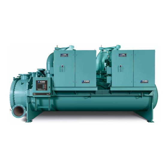
- Page 7 FORM 160.79-O3 ISSUE DATE: 11/09/2018 LIST OF FIGURES FIGURE 1 - Model YD Chiller ............................9 FIGURE 2 - Chiller Operation Flow Chart .......................15 FIGURE 3 - OptiView™ Control Center ........................25 FIGURE 4 - Home Screen ............................30 FIGURE 5 - System Screen ............................33 FIGURE 6 - Evaporator Screen ..........................35 FIGURE 7 - Condenser Screen ..........................38 FIGURE 8 - Refrigerant Level Control Screen ......................40...
- Page 8 FORM 160.79-O3 ISSUE DATE: 11/09/2018 LIST OF FIGURES (CONT'D) FIGURE 56 - Sample Printout (Schedule) ......................154 FIGURE 57 - Sample Printout (Sales Order)......................154 FIGURE 58 - Sample Printout (History).........................156 FIGURE 59 - Sample Printout (Security Log Report) ....................158 FIGURE 60 - Sample Printout (Trend Data New or Existing Points) ..............158 FIGURE 61 - Sample Printout (Custom Screen Report) ..................158 JOHNSON CONTROLS...
-
Page 9: Section 1 - Description Of System And Fundamentals Of Operation
FORM 160.79-O3 ISSUE DATE: 11/09/2018 SECTION 1 – DESCRIPTION OF SYSTEM AND FUNDAMENTALS OF OPERATION SYSTEM OPERATION DESCRIPTION running compressor. An end switch at both the closed The following is a high level description of the chill- and open positions provides indication of full open and er control. -
Page 10: Compressor Starting
FORM 160.79-O3 SECTION 1 – DESCRIPTION OF SYSTEM AND FUNDAMENTALS OF OPERATION ISSUE DATE: 11/09/2018 A lockout can be performed on a compressor to pre- the second compressor from being brought on line. vent it from running. Only one compressor at a time The COMPRESSOR LOCKOUT setpoint can be used can be locked out. - Page 11 FORM 160.79-O3 SECTION 1 – DESCRIPTION OF SYSTEM AND FUNDAMENTALS OF OPERATION ISSUE DATE: 11/09/2018 intervals. If the rate of change of the Liquid Tempera- is not performed. The offset calculation from the Lead ture (Delta T Rate) is less than the programmed Mini- compressor start is used.
- Page 12 FORM 160.79-O3 SECTION 1 – DESCRIPTION OF SYSTEM AND FUNDAMENTALS OF OPERATION SECTION 1 – DESCRIPTION OF SYSTEM AND FUNDAMENTALS OF OPERATION ISSUE DATE: 11/09/2018 On the Refrigerant Level Control Screen, the Refriger- With the Lead compressor running and it is determined ant Level Override Mode displays “Valve Preset”...
-
Page 13: Compressor Shutdown
FORM 160.79-O3 SECTION 1 – DESCRIPTION OF SYSTEM AND FUNDAMENTALS OF OPERATION ISSUE DATE: 11/09/2018 After the Lead Compressor Pulldown Time Setpoint “Oil Pump [#1/#2] - Differential Pressure Calibration” has elapsed, the chiller current limit will be limited to “Oil Pump [#1/#2] – Pressure Transducer Out of the value programmed for the Chiller Current Limit Range”... - Page 14 FORM 160.79-O3 SECTION 1 – DESCRIPTION OF SYSTEM AND FUNDAMENTALS OF OPERATION ISSUE DATE: 11/09/2018 the Discharge Valve is then driven closed. When the • "Discharge Valve X – Valve Not Closed” Discharge Valve has fully closed (or 40 seconds have •...
-
Page 15: Figure 2 - Chiller Operation Flow Chart
FORM 160.79-O3 SECTION 1 – DESCRIPTION OF SYSTEM AND FUNDAMENTALS OF OPERATION ISSUE DATE: 11/09/2018 YD Dual Compressor Chiller Chiller Standby Electro-Mechanical Starter Chiller Start Sequence Compressor Start Inhibit Disch Valves Closed? Chiller Start Requirement Is a Compressor in Select Lead Compressor Service Lockout Select the other Select the Compressor... - Page 16 FORM 160.79-O3 SECTION 1 – DESCRIPTION OF SYSTEM AND FUNDAMENTALS OF OPERATION ISSUE DATE: 11/09/2018 YD Dual Compressor Chiller Electro-Mechanical Starter Chiller Start Sequence 1 compressor running (from Page 1) Is La Compressor in Don't start lag compressor Service Lockout Single Compressor Mode? Lead...
- Page 17 FORM 160.79-O3 SECTION 1 – DESCRIPTION OF SYSTEM AND FUNDAMENTALS OF OPERATION ISSUE DATE: 11/09/2018 YD Dual Compressor Chiller Normal Safety Checks Electro-Mechanical Starter (Except for oil low temp Chiller Start Sequence differential) Lag Compr Startup PRVs and Start Lag Compressor From Disch Valve on Motor...
- Page 18 FORM 160.79-O3 SECTION 1 – DESCRIPTION OF SYSTEM AND FUNDAMENTALS OF OPERATION ISSUE DATE: 11/09/2018 YD Dual Compressor Chiller Electro Mechanical Chiller 2 Compressors Running Capacity Cycling (Lag Compressor Stop) Sequence (from Page 3) Has Lag Compressor Run >30 Min As motor currents fall below 50% with Motor Current two compressors running, a single...
- Page 19 FORM 160.79-O3 SECTION 1 – DESCRIPTION OF SYSTEM AND FUNDAMENTALS OF OPERATION ISSUE DATE: 11/09/2018 YD Dual Compressor Chiller Electro Mechanical Starter Chiller Soft Shutdown 2 Compressors Running 1 Compressor Running (from Page 3) (from Page 1 or 4) Chiller normal Chiller normal or cycling stop or cycling stop...
- Page 20 FORM 160.79-O3 SECTION 1 – DESCRIPTION OF SYSTEM AND FUNDAMENTALS OF OPERATION ISSUE DATE: 11/09/2018 YD Dual Compressor Chiller Electro-Mechanical Starter Chiller Fault Stop (manual or auto restart) 2 Compressors Running 1 Compressor Running (from Page 3) (from Page 1 or 4) Chiller Fault Chiller Fault Condition...
- Page 21 FORM 160.79-O3 SECTION 1 – DESCRIPTION OF SYSTEM AND FUNDAMENTALS OF OPERATION ISSUE DATE: 11/09/2018 YD Dual Compressor Chiller Anti-Surge Control Algorithm Chiller Running Two Compressor Mode. Lead Compressor controlling LChWT Lag Compressor following current of Lead Are Compressor Motor Currents Equal within 20% Are vanes on the lower current compressor open more than the...
- Page 22 FORM 160.79-O3 ISSUE DATE: 11/09/2018 THIS PAGE INTENTIONALLY LEFT BLANK. JOHNSON CONTROLS...
-
Page 23: Section 2 - Optiview Control Center
FORM 160.79-O3 ISSUE DATE: 11/09/2018 SECTION 2 – OPTIVIEW CONTROL CENTER INTRODUCTION The YORK OptiView™ Control Center is a micro- Advanced Diagnostics and troubleshooting informa- processor based control system for R134a centrifugal tion for Service Technicians are included in the Service chillers. - Page 24 FORM 160.79-O3 SECTION 2 – OPTIVIEW CONTROL CENTER ISSUE DATE: 11/09/2018 Software versions are alpha-numeric codes that repre- sent the application and revision level per below. Each time the software is revised, the level increments. Y.OPT.11.xx.yzz: • Y – Commercial chiller •...
-
Page 25: Optiview Control Center In Detail
FORM 160.79-O3 SECTION 2 – OPTIVIEW CONTROL CENTER ISSUE DATE: 11/09/2018 OPTIVIEW CONTROL CENTER IN DETAIL The OptiView™ Control Center display is highlighted is considered in the STOP/RESET position. When in by a full screen graphics display. This display is nested the middle position, this is considered the RUN state. -
Page 26: Overview Of Interface
FORM 160.79-O3 SECTION 2 – OPTIVIEW CONTROL CENTER ISSUE DATE: 11/09/2018 OVERVIEW OF INTERFACE fault when power is applied to the system), and use the The new graphical display on each control panel al- LOGIN button or utilize the CHANGE SETPOINTS lows a wide variety of information to be presented to key described below. - Page 27 FORM 160.79-O3 SECTION 2 – OPTIVIEW CONTROL CENTER ISSUE DATE: 11/09/2018 Pressing the p key, sets the entry value to the de- Free Cursor fault for that setpoint. Pressing the q key, clears On screens containing many setpoints, a specific “soft” the present entry.
- Page 28 FORM 160.79-O3 SECTION 2 – OPTIVIEW CONTROL CENTER ISSUE DATE: 11/09/2018 Home Screen Languages System Screen The Screens can be displayed in various languages. Language selection is done on the USER Screen. The Evaporator desired language is selected from those available. Condenser Not all languages are available.
-
Page 29: Analog Input Ranges
FORM 160.79-O3 SECTION 2 – OPTIVIEW CONTROL CENTER ISSUE DATE: 11/09/2018 ANALOG INPUT RANGES The following table indicates the valid display range for each of the analog input values. In the event that the input sensor is reading a value outside of these ranges, the <... -
Page 30: Home Screen
FORM 160.79-O3 SECTION 2 – OPTIVIEW CONTROL CENTER ISSUE DATE: 11/09/2018 HOME SCREEN LD27843 FIGURE 4 - HOME SCREEN When the chiller system is powered on, the above de- % Full Load Amps fault display appears. The primary values which must Displays the percentage of compressor motor full load be monitored and controlled are shown on this screen. - Page 31 FORM 160.79-O3 SECTION 2 – OPTIVIEW CONTROL CENTER ISSUE DATE: 11/09/2018 PROGRAMMABLE Message Clear Login Access Level Required: SERVICE Access Level Required: VIEW When certain safety or cycling conditions have been The OptiView™ Panel restricts certain operations detected and the chiller has been shutdown, the main based on password entry by the operator.
- Page 32 FORM 160.79-O3 SECTION 2 – OPTIVIEW CONTROL CENTER ISSUE DATE: 11/09/2018 NAVIGATION System Motor A detailed view of the motor controller parameters, Used to provide additional system information. specific to the controller type presently utilized on the Evaporator chiller system. This allows programming of the Cur- A detailed view of all evaporator parameters, including rent Limit and the Pulldown Demand Limit values.
-
Page 33: System Screen
FORM 160.79-O3 SECTION 2 – OPTIVIEW CONTROL CENTER ISSUE DATE: 11/09/2018 SYSTEM SCREEN LD27844 FIGURE 5 - SYSTEM SCREEN This screen gives a general overview of common Oil Pressure chiller parameters for both shells. Displays the pressure differential between the Pump oil pressure transducer (output of oil filter) for com- pressor #2 and the Sump oil pressure transducer. - Page 34 FORM 160.79-O3 SECTION 2 – OPTIVIEW CONTROL CENTER ISSUE DATE: 11/09/2018 Evaporator Pressure Chiller Current Limit Setpoint Displays the present refrigerant pressure in the evapo- Displays the Chiller Current Limit Setpoint. The Chill- rator. er Current Limit Setpoint could be from a 0-20 mA, 4-20 mA, 0-10 VDC or 2-10 VDC input in Analog re- Evaporator Saturation Temperature mote mode or PWM input in Digital remote mode or...
-
Page 35: Evaporator Screen
FORM 160.79-O3 SECTION 2 – OPTIVIEW CONTROL CENTER ISSUE DATE: 11/09/2018 EVAPORATOR SCREEN LD27845 FIGURE 6 - EVAPORATOR SCREEN This screen displays a cutaway view of the chiller Evaporator Saturation Temperature evaporator. All setpoints relating to the evaporator side Displays the present saturation temperature in the of the chiller are maintained on this screen. - Page 36 FORM 160.79-O3 SECTION 2 – OPTIVIEW CONTROL CENTER ISSUE DATE: 11/09/2018 Restart Leaving Chilled Liquid Temperature Cycling Displays the Leaving Chilled Liquid Temperature at Effective Offset - Shutdown which the chiller will restart after it has shut down due to Access Level Required: OPERATOR over-cooling temperature.
- Page 37 FORM 160.79-O3 SECTION 2 – OPTIVIEW CONTROL CENTER ISSUE DATE: 11/09/2018 NAVIGATION Refrigerant (Enabled / Disabled) Access Level Required: SERVICE Home When an Evaporator Refrigerant Sensor has been in- Access Level Required VIEW stalled it must be enabled via this toggle before the sys- Causes an instant return to the Home Screen.
-
Page 38: Condenser Screen
FORM 160.79-O3 SECTION 2 – OPTIVIEW CONTROL CENTER ISSUE DATE: 11/09/2018 CONDENSER SCREEN LD27846 FIGURE 7 - CONDENSER SCREEN This screen displays a cutaway view of the chiller Drop Leg Refrigerant Temperature condenser. Animation indicates condenser liquid flow. Displays the temperature of the refrigerant in the drop This screen also serves as a gateway to controlling the leg between the condenser and evaporator shells, if the Refrigerant Level. - Page 39 FORM 160.79-O3 SECTION 2 – OPTIVIEW CONTROL CENTER ISSUE DATE: 11/09/2018 Level Control Valve Command NAVIGATION Displays the current Refrigerant Valve command. Home Access Level Required: VIEW PROGRAMMABLE Causes an instant return to the Home Screen. High Pressure Warning Threshold Refrigerant Level Control Access Level Required: SERVICE Access Level Required: SERVICE...
-
Page 40: Refrigerant Level Control Screen
FORM 160.79-O3 SECTION 2 – OPTIVIEW CONTROL CENTER ISSUE DATE: 11/09/2018 REFRIGERANT LEVEL CONTROL SCREEN LD27847 FIGURE 8 - REFRIGERANT LEVEL CONTROL SCREEN This screen displays a cutaway view of the chiller con- Subcooler Effectiveness denser, along with the liquid refrigerant level sensor The Subcooler Effectiveness is evaluated with the fol- and variable orifice. - Page 41 FORM 160.79-O3 SECTION 2 – OPTIVIEW CONTROL CENTER ISSUE DATE: 11/09/2018 PROGRAMMABLE will decrease the current Condenser Level Control Level Setpoint Valve Command by an amount equal to the Manual Displays the setpoint to which the refrigerant level is Increment, with a minimum of 0.0%. being controlled.
-
Page 42: Main Compressor Screen
FORM 160.79-O3 SECTION 2 – OPTIVIEW CONTROL CENTER ISSUE DATE: 11/09/2018 MAIN COMPRESSOR SCREEN LD27848 FIGURE 9 - MAIN COMPRESSOR SCREEN This screen displays a cutaway of the chiller compres- Compressor 1 sors, revealing the impellers. Animation of the impel- Oil Pressure ler indicates when the compressor is running. - Page 43 FORM 160.79-O3 SECTION 2 – OPTIVIEW CONTROL CENTER ISSUE DATE: 11/09/2018 Capacity Control Discharge Temperature Displays the temperature of the refrigerant in its gas- Access Level Required: VIEW eous state at the discharge of the compressor #1 as it Navigates to the Capacity Control Screen where the travels to the condenser.
-
Page 44: Compressor 1 Or 2 Screen
FORM 160.79-O3 SECTION 2 – OPTIVIEW CONTROL CENTER ISSUE DATE: 11/09/2018 COMPRESSOR 1 OR 2 SCREEN LD27849 FIGURE 10 - COMPRESSOR 1 SCREEN This screen displays a cutaway of the compressor #1 or beginning ten (10) seconds into the system pre-lube #2, revealing the impeller. - Page 45 FORM 160.79-O3 SECTION 2 – OPTIVIEW CONTROL CENTER ISSUE DATE: 11/09/2018 HGBP Command High Pressure Switch Indicates the Hot Gas Bypass Command 0% (Closed Indicates the status of the compressor High Pressure to 100% (Open). Only displayed if Hot Gas option is Switch.
-
Page 46: Proximity Probe Calibration Screen
FORM 160.79-O3 SECTION 2 – OPTIVIEW CONTROL CENTER ISSUE DATE: 11/09/2018 PROXIMITY PROBE CALIBRATION SCREEN LD27850 FIGURE 11 - PROXIMITY PROBE CALIBRATION SCREEN This screen displays a cutaway view of the chiller com- Oil Pressure pressor, revealing the proximity probe sensor and pro- Displays the pressure differential between the pump oil vides the capability of calibrating the proximity probe pressure transducer (compressor bearing input) and the... - Page 47 FORM 160.79-O3 SECTION 2 – OPTIVIEW CONTROL CENTER ISSUE DATE: 11/09/2018 Cancel Calibration NAVIGATION This option only becomes available after the calibra- Home tion has started. Causes an instant return to the Home Screen. Accept Calibration Compressor The key is pressed to accept the calibration. This key Return to the Compressor Screen.
-
Page 48: Pre-Rotation Vanes Calibration Screen
FORM 160.79-O3 SECTION 2 – OPTIVIEW CONTROL CENTER ISSUE DATE: 11/09/2018 PRE-ROTATION VANES CALIBRATION SCREEN LD27851 FIGURE 12 - PRE-ROTATION VANES CALIBRATION SCREEN This screen displays a cutaway view of the chiller com- PRV Feedback Voltage pressor, revealing the pre-rotation vanes and provides Displays the Pre-Rotation Vanes position potentiom- the capability of calibrating the pre-rotation vanes. - Page 49 FORM 160.79-O3 SECTION 2 – OPTIVIEW CONTROL CENTER ISSUE DATE: 11/09/2018 Start Calibration NAVIGATION Pressing this button initiates the PRV Calibration se- Home quence. This option is hidden after calibration has Causes an instant return to the Home Screen. started. Compressor Cancel Calibration Return to the Compressor Screen.
-
Page 50: Variable Geometry Diffuser (Vgd) Screen
FORM 160.79-O3 SECTION 2 – OPTIVIEW CONTROL CENTER ISSUE DATE: 11/09/2018 VARIABLE GEOMETRY DIFFUSER (VGD) SCREEN LD27852 FIGURE 13 - VARIABLE GEOMETRY DIFFUSER 1 SCREEN This screen displays information pertinent to the com- Mach Number pressor VGD operation. Also, the VGD can be manu- Displays the speed of the compressor. - Page 51 FORM 160.79-O3 SECTION 2 – OPTIVIEW CONTROL CENTER ISSUE DATE: 11/09/2018 Surge Detected (LED) [VGD] Close (Manual) Illuminates momentarily when a surge is detected by This key puts the VGD in manual mode and sends a the Surge Protection feature. If equipped with a VSD close command to the VGD.
-
Page 52: Variable Geometry Diffuser (Vgd) Setpoints Screen
FORM 160.79-O3 SECTION 2 – OPTIVIEW CONTROL CENTER ISSUE DATE: 11/09/2018 VARIABLE GEOMETRY DIFFUSER (VGD) SETPOINTS SCREEN LD27853 FIGURE 14 - VARIABLE GEOMETRY DIFFUSER SETPOINTS SCREEN The Variable Geometry Diffuser setpoints for VGD 1 VGD Closing (LED) and 2 are maintained on this screen. All setpoints re- Illuminates when a close signal is being applied to the quire a login access level of Service unless otherwise VGD. - Page 53 FORM 160.79-O3 SECTION 2 – OPTIVIEW CONTROL CENTER ISSUE DATE: 11/09/2018 PROGRAMMABLE PRV VGD Inhibit Extreme Stall Duration (10 to 20 minutes; default 10) – This setpoint applies (40% to 100%; default 90%). Applicable to dual com- pressor operation only. Both VGD’s will be pulsed to both VGD controls.
- Page 54 FORM 160.79-O3 SECTION 2 – OPTIVIEW CONTROL CENTER ISSUE DATE: 11/09/2018 The minimum difference between the High Limit VGD 1 setpoint and the Low Limit setpoint is 0.1 VDC. If a Access Level Required: Service Low Limit setpoint is entered which is less than 0.1 Causes an instant return to the Variable Geometry Dif- VDC below the High Limit setpoint, the High Limit fuser 1 Screen...
-
Page 55: Variable Geometry Diffuser (Vgd) Calibration Screen
FORM 160.79-O3 SECTION 2 – OPTIVIEW CONTROL CENTER ISSUE DATE: 11/09/2018 VARIABLE GEOMETRY DIFFUSER (VGD) CALIBRATION SCREEN LD27854 FIGURE 15 - VARIABLE GEOMETRY DIFFUSER 1 CALIBRATION SCREEN This screen allows calibration of the compressor Calibration Messages Variable Geometry Diffuser position potentiometer. These are text messages which step the user through the calibration process and indicate its success or R e q u i r e s a l o g i n a c c e s s l e v e l o f... -
Page 56: Hot Gas Bypass Screen
FORM 160.79-O3 SECTION 2 – OPTIVIEW CONTROL CENTER ISSUE DATE: 11/09/2018 HOT GAS BYPASS SCREEN LD27855 FIGURE 16 - HOT GAS BYPASS SCREEN This screen displays a cutaway view of the Hot Gas Lead PRV Position Bypass Valve. All setpoints relating to Hot Gas Bypass Displays the position of the Lead Compressor Pre- control are maintained on this screen. - Page 57 FORM 160.79-O3 SECTION 2 – OPTIVIEW CONTROL CENTER ISSUE DATE: 11/09/2018 Lead VGD Position Hold Period Displays the position of the Lead Compressor VGD This is the period of time after no more surges are over the range of 0% (closed) to 100% (fully open). detected that the Hot Gas Valve will begin to close.
-
Page 58: Surge Protection Screen
FORM 160.79-O3 SECTION 2 – OPTIVIEW CONTROL CENTER ISSUE DATE: 11/09/2018 SURGE PROTECTION SCREEN LD27856 FIGURE 17 - SURGE PROTECTION SCREEN This screen displays both single compressor and dual Surge Window Count compressor surge protection parameters. An LED illu- Displays the number of single-compressor surge events minates when a surge event is detected. - Page 59 FORM 160.79-O3 SECTION 2 – OPTIVIEW CONTROL CENTER ISSUE DATE: 11/09/2018 Dual Compressor Operation Lead Variable Geometry Diffuser Position Surge Window Time Displays the position of the lead compressor Variable When the lag compressor is started, this value counts Geometry Diffuser. up from 1 minute to the time programmed as the COUNT WINDOW Setpoint.
-
Page 60: Surge Protection Screen (Single-Compressor Operation)
FORM 160.79-O3 SECTION 2 – OPTIVIEW CONTROL CENTER ISSUE DATE: 11/09/2018 SURGE PROTECTION SCREEN (SINGLE-COMPRESSOR OPERATION) LD27857 FIGURE 18 - SURGE PROTECTION SCREEN (SINGLE COMPRESSOR OPERATION) This screen displays the single-compressor surge pro- discarded and the number of surge events in the most tection parameters. - Page 61 FORM 160.79-O3 SECTION 2 – OPTIVIEW CONTROL CENTER ISSUE DATE: 11/09/2018 Extended Run Time Remaining the completion of this period, a safety shutdown is Displays the time remaining in the 10-minute “EX- performed and “Surge Protection – Excess Surge” is TENDED RUN”...
- Page 62 FORM 160.79-O3 SECTION 2 – OPTIVIEW CONTROL CENTER ISSUE DATE: 11/09/2018 • If both the SHUTDOWN and EXTENDED RUN Clear Surge Count setpoint are Enabled, the 10 minute Extended Access Level Required: ADMIN RUN mode is invoked as described above. How- Allows user to set the Single Compressor Total Surge ever, if the SURGE WINDOW COUNT exceeds Count to zero.
-
Page 63: Surge Protection Screen (Dual-Compressor Operation)
FORM 160.79-O3 SECTION 2 – OPTIVIEW CONTROL CENTER ISSUE DATE: 11/09/2018 SURGE PROTECTION SCREEN (DUAL-COMPRESSOR OPERATION) LD27858 FIGURE 19 - SURGE PROTECTION SCREEN (DUAL COMPRESSOR OPERATION) Surge Window Count This screen displays the dual-compressor surge protec- tion parameters. The setpoints applicable to this feature Displays the number of dual-compressor surge events are maintained here. - Page 64 FORM 160.79-O3 SECTION 2 – OPTIVIEW CONTROL CENTER ISSUE DATE: 11/09/2018 Lead Compressor motor currents are balanced with 20%, whereupon it Identifies the compressor that has been assigned as the automatically clears. If the Surge Window Count ex- lead compressor. ceeds the Count Limit, the lag compressor is taken off Lead % Full Load Amps line and “Warning –...
-
Page 65: Capacity Control Screen
FORM 160.79-O3 SECTION 2 – OPTIVIEW CONTROL CENTER ISSUE DATE: 11/09/2018 CAPACITY CONTROL SCREEN LD27859 FIGURE 20 - CAPACITY CONTROL SCREEN This screen displays the pertinent parameters associat- [Motor Current % FLA] Override Threshold ed with capacity control in relation to Leaving Chilled Displays the active input current percent limit, which Liquid temperature, current and pressure overrides, is the minimum of Local Input Current Limit, Remote... - Page 66 FORM 160.79-O3 SECTION 2 – OPTIVIEW CONTROL CENTER ISSUE DATE: 11/09/2018 Active LCHLT Setpoint Displays the active temperature setpoint to which the • Input Current chiller is set to control liquid leaving the evaporator. • Motor Current The Active Setpoint is a target to the Local, Remote or BAS (ISN) LCHLT programmed setpoint, depending •...
- Page 67 FORM 160.79-O3 SECTION 2 – OPTIVIEW CONTROL CENTER ISSUE DATE: 11/09/2018 Manual Increment NAVIGATION Sets the percentage amount that the PRV or HGBP will Home move with each press of the Manual Increase or De- Causes an instant return to the Home screen. crease button.
-
Page 68: Capacity Control Setpoints Screen
FORM 160.79-O3 SECTION 2 – OPTIVIEW CONTROL CENTER ISSUE DATE: 11/09/2018 CAPACITY CONTROL SETPOINTS SCREEN LD27860 FIGURE 21 - CAPACITY CONTROL SETPOINTS SCREEN This screen displays the capacity control setpoints. during operation, the active setpoint is ramped to the A Service Level password is required to access this new value at this rate. -
Page 69: Anti-Surge Tuning Screen
FORM 160.79-O3 SECTION 2 – OPTIVIEW CONTROL CENTER ISSUE DATE: 11/09/2018 ANTI-SURGE TUNING SCREEN LD27861 FIGURE 22 - ANTI-SURGE TUNING SCREEN Lead PRV Start Position This screen displays the Anti-Surge Tuning param- eters. A Service Level password is required to access The desired start position of the Lead compressor PRV. -
Page 70: Capacity Compressor Cycling Screen
FORM 160.79-O3 SECTION 2 – OPTIVIEW CONTROL CENTER ISSUE DATE: 11/09/2018 CAPACITY COMPRESSOR CYCLING SCREEN LD27862 FIGURE 23 - CAPACITY COMPRESSOR CYCLING SCREEN every minute. The previous reading is subtracted from This screen allows the user to specify the chiller load the present reading and the last 5 results are averaged conditions under which the lag compressor is cycled on to obtain a five-point rolling average. - Page 71 FORM 160.79-O3 SECTION 2 – OPTIVIEW CONTROL CENTER ISSUE DATE: 11/09/2018 Lag PRV Position “Checking Minimum Rate” and “Waiting Mini- mum Rate Time” Displays the position of the lag compressor pre-rota- tion vanes position. When the 8 minute Pulldown Delay is finished, the Chiller Pulldown Period continues until the Leaving Lag VGD Position Chilled Liquid Temperature is within 2ºF of the Leav-...
- Page 72 FORM 160.79-O3 SECTION 2 – OPTIVIEW CONTROL CENTER ISSUE DATE: 11/09/2018 Maximum Delta T Setpoint (whereupon “Checking Time Remaining Maximum Delta T” is displayed), the Maximum Delta Displays the time remaining on the following timers: T Time has expired (whereupon “Preparing Chiller for •...
- Page 73 FORM 160.79-O3 SECTION 2 – OPTIVIEW CONTROL CENTER ISSUE DATE: 11/09/2018 Low Load and Low Load Time Single Mode - The operation is restricted to one com- Access Level Required: SERVICE pressor only. When starting the chiller in Single Com- Allows the user to define the criteria that determines pressor mode, the operator does not designate which if the lag compressor should be shutdown because...
-
Page 74: Oil Sump Screen
FORM 160.79-O3 SECTION 2 – OPTIVIEW CONTROL CENTER ISSUE DATE: 11/09/2018 OIL SUMP SCREEN LD27863 FIGURE 24 - OIL SUMP SCREEN This screen displays a close-up of the chiller oil sump Pump Oil Pressure (HOP) with pertinent oil system status, pressures and tem- Displays the high side oil pressure measured at the peratures. - Page 75 FORM 160.79-O3 SECTION 2 – OPTIVIEW CONTROL CENTER ISSUE DATE: 11/09/2018 Pulldown Time Remaining Pulldown Time Remaining Displays the time remaining until the user programmed Displays the time remaining until the user programmed Setpoint Oil Pressure is used. While this clock is dec- Setpoint Oil Pressure is used.
-
Page 76: Oil Pump 1 And 2 Screen
FORM 160.79-O3 SECTION 2 – OPTIVIEW CONTROL CENTER ISSUE DATE: 11/09/2018 OIL PUMP 1 AND 2 SCREEN LD27864 FIGURE 25 - OIL PUMP 1 SCREEN This screen displays the chiller oil sump along with Pump Oil Pressure (HOP) the compressor oil cooler. All of the setpoints for com- Displays the high side oil pressure measured at the pressor Variable Speed Drive Oil Pump are maintained compressor bearing input. - Page 77 FORM 160.79-O3 SECTION 2 – OPTIVIEW CONTROL CENTER ISSUE DATE: 11/09/2018 Pulldown Time Remaining Variable Speed Oil Pump Speed Control Displays the time remaining until the user programmed Setpoint Oil Pressure is used. While this clock is decre- Access Level Required: SERVICE menting, the Target Oil Pressure Setpoint (fixed at 45.0 This key allows the user to specify a fixed speed at PSID) is in effect.
-
Page 78: Motor Starter Screen
FORM 160.79-O3 SECTION 2 – OPTIVIEW CONTROL CENTER ISSUE DATE: 11/09/2018 MOTOR STARTER SCREEN CYCLING SHUTDOWN - AUTO RESTART 1 22 PM VSD #2 - SERIAL COMMUNICATIONS LD27865 FIGURE 26 - MOTOR STARTER SCREEN This screen displays information pertaining to the Operating Hours Motor Starter. - Page 79 FORM 160.79-O3 SECTION 2 – OPTIVIEW CONTROL CENTER ISSUE DATE: 11/09/2018 Lead Compressor Pulldown Demand Limit NAVIGATION Access Level Required: OPERATOR Home Sets the maximum current draw of the lead compres- Access Level Required: VIEW sor during initial start for the selected Pulldown Time. Returns user to the Home screen.
-
Page 80: Low Voltage Variable Speed Drive Screen
FORM 160.79-O3 SECTION 2 – OPTIVIEW CONTROL CENTER ISSUE DATE: 11/09/2018 LOW VOLTAGE VARIABLE SPEED DRIVE SCREEN LD27866 FIGURE 27 - LOW VOLTAGE VARIABLE SPEED DRIVE SCREEN This screen displays information pertaining to the PRV Position Low Voltage Variable Speed Drive (VSD), if installed. Displays the Pre-rotation Vane position as a value be- There are two similar screens available: one for VSD 1 tween 0 and 100%. - Page 81 FORM 160.79-O3 SECTION 2 – OPTIVIEW CONTROL CENTER ISSUE DATE: 11/09/2018 Voltage Total Harmonic Distortion - (L1, L2, NAVIGATION Home Displays the Total Harmonic Distortion (THD) for each Access Level Required: VIEW of the voltage lines as calculated by the optional filter. Returns user to the Home screen.
-
Page 82: Medium Voltage Variable Speed Drive Screen
FORM 160.79-O3 SECTION 2 – OPTIVIEW CONTROL CENTER ISSUE DATE: 11/09/2018 MEDIUM VOLTAGE VARIABLE SPEED DRIVE SCREEN LD27867 FIGURE 28 - MEDIUM VOLTAGE VARIABLE SPEED DRIVE SCREEN This screen displays information pertaining to the Me- Output Voltage dium Voltage Variable Speed Drive (MVVSD), if in- Displays the output voltage measured to the motor. - Page 83 FORM 160.79-O3 SECTION 2 – OPTIVIEW CONTROL CENTER ISSUE DATE: 11/09/2018 MVVSD Model VSD Cooling Fans Output (LED) Displays the model number as received from the MV- Illuminates when the digital output from the MVVSD VSD. control is commanding the Cooling Fans to RUN. Motor Voltage Rating Precharge Relay Output (LED) Displays the voltage rating of the MVVSD as received...
-
Page 84: Motor Lubrication Screen
FORM 160.79-O3 SECTION 2 – OPTIVIEW CONTROL CENTER ISSUE DATE: 11/09/2018 MOTOR LUBRICATION SCREEN LD27868 FIGURE 29 - MOTOR LUBRICATION SCREEN This feature provides an indication when the compres- DISPLAY ONLY sor motor lubrication is required. The lubrication re- Date of Last Motor Lubrication Warning or quirement and notification is based on the “Operating Fault Hours Since Last Motor Lubrication”. - Page 85 FORM 160.79-O3 SECTION 2 – OPTIVIEW CONTROL CENTER ISSUE DATE: 11/09/2018 Operating Hours Since Last Motor Lubrication 3. Use the ▲▼keys to scroll sequentially through Displays the run hours (in whole hours) accumulated the alphabet to enter letters or numbers. Each time since the last motor lubrication.
- Page 86 FORM 160.79-O3 SECTION 2 – OPTIVIEW CONTROL CENTER ISSUE DATE: 11/09/2018 Shutdowns NAVIGATION Access Level Required: SERVICE Home If the Auto Lube setpoint above is set to DISABLED, Access Level Required: VIEW the SHUTDOWN Setpoint is used to enable or dis- Causes an instant return to the Home screen.
-
Page 87: Variable Speed Drive (Vsd) Details Screen
FORM 160.79-O3 SECTION 2 – OPTIVIEW CONTROL CENTER ISSUE DATE: 11/09/2018 VARIABLE SPEED DRIVE (VSD) DETAILS SCREEN LD27869 FIGURE 30 - VARIABLE SPEED DRIVE (VSD) DETAILS SCREEN Pulldown Demand Time Left This screen displays more detailed information per- taining to the Variable Speed Drives (VSDs). There are Displays the time remaining in the programmed pull- two separate screens: one for VSD 1 and one for VSD down period if the value is nonzero. - Page 88 FORM 160.79-O3 SECTION 2 – OPTIVIEW CONTROL CENTER ISSUE DATE: 11/09/2018 DC Bus Voltage PROGRAMMABLE Displays the DC Bus voltage as reported by the VSD. None. DC Inverter Link Current Displays the DC Inverter link current as reported by NAVIGATION the VSD.
-
Page 89: Harmonic Filter Details Screen
FORM 160.79-O3 SECTION 2 – OPTIVIEW CONTROL CENTER ISSUE DATE: 11/09/2018 HARMONIC FILTER DETAILS SCREEN LD27870 FIGURE 31 - HARMONIC FILTER DETAILS SCREEN This screen displays more detailed information per- Operating Mode (Run / Stop) taining to the optional IEEE-519 Harmonic Filter. Indicates whether the Harmonic Filter is operating or There are two separate screens. - Page 90 FORM 160.79-O3 SECTION 2 – OPTIVIEW CONTROL CENTER ISSUE DATE: 11/09/2018 Voltage Total Harmonic Distortion (L1, L2, L3) Precharge Contractor (LED) Displays the 3-phase voltage Total Harmonic Distor- Indicates whether the output to the precharge contrac- tion (THD) measurements. tor is energized. RMS Filter Current (L1, L2, L3) PROGRAMMABLE Displays the 3-phase filter current values as measured...
-
Page 91: Motor Details Screen
FORM 160.79-O3 SECTION 2 – OPTIVIEW CONTROL CENTER ISSUE DATE: 11/09/2018 MOTOR DETAILS SCREEN LD27871 FIGURE 32 - MOTOR DETAILS SCREEN PRV Position This screen displays information pertinent to the op- tional Motor Monitoring feature. The feature is an ad- Displays the present Pre-rotation Vanes position as a ditional circuit board and sensors for each motor which value between 0% (closed) and 100% (full open). - Page 92 FORM 160.79-O3 SECTION 2 – OPTIVIEW CONTROL CENTER ISSUE DATE: 11/09/2018 Motor Cooling Coil Leak Detected (LED) Vibration Baseline Displays the Shaft End and Opposite End vibration val- Illuminates when the enabled Motor Cooling Coil ues established during the initial startup of the chiller. Leak Detector indicates a leak.
-
Page 93: Electro-Mechanical Starter Screen
FORM 160.79-O3 SECTION 2 – OPTIVIEW CONTROL CENTER ISSUE DATE: 11/09/2018 ELECTRO-MECHANICAL STARTER SCREEN LD27872 FIGURE 33 - ELECTRO-MECHANICAL STARTER SCREEN This screen displays all information pertaining to both with each motor having an equal FLA rating. For ex- compressor motors operation when the chiller is using ample, if the Chiller FLA is 1600 amps, the FLA of Electro-Mechanical Starters. - Page 94 FORM 160.79-O3 SECTION 2 – OPTIVIEW CONTROL CENTER ISSUE DATE: 11/09/2018 Motor Current Limit Setpoint at 70%, the Chiller Current is limited to 1120 amps. Displays the current limit being applied to compressor If only one motor is running, the Motor Current Limit #1 motor.
- Page 95 FORM 160.79-O3 SECTION 2 – OPTIVIEW CONTROL CENTER ISSUE DATE: 11/09/2018 NAVIGATION Home Motor 2 Details Access Level Required: VIEW Access Level Required: VIEW Displays the motor temperatures and vibration read- Causes a return to the Home screen. ings if the optional Motor Monitoring system is in- Motor 1 Details stalled on Motor 2.
-
Page 96: Setpoints Screen
FORM 160.79-O3 SECTION 2 – OPTIVIEW CONTROL CENTER ISSUE DATE: 11/09/2018 SETPOINTS SCREEN LD27873 FIGURE 34 - SETPOINTS SCREEN This screen provides a convenient location for pro- Leaving Chilled Liquid Temperature Cycling Shut- gramming the most common setpoints involved in the down Offset from the Leaving Chilled Liquid Tem- chiller control. - Page 97 FORM 160.79-O3 SECTION 2 – OPTIVIEW CONTROL CENTER ISSUE DATE: 11/09/2018 PROGRAMMABLE Temperature setpoint. It is programmable over a range Local Leaving Chilled Liquid Temperature - of 1°F to 70°F below the setpoint, to a minimum cutout Setpoint of 36°F (water) or 6°F (brine). It establishes the mini- Access Level Required: OPERATOR mum allowed temperature for the Leaving Chilled Liq- This value allows the user to define the Leaving...
- Page 98 FORM 160.79-O3 SECTION 2 – OPTIVIEW CONTROL CENTER ISSUE DATE: 11/09/2018 Remote Analog Input Range NAVIGATION Access Level Required: OPERATOR Home Defines the remote signal range applied for remote re- Access Level Required: VIEW set of the Leaving Chilled Liquid temperature Setpoint Causes an instant return to the Home screen.
-
Page 99: Setup Screen
FORM 160.79-O3 SECTION 2 – OPTIVIEW CONTROL CENTER ISSUE DATE: 11/09/2018 SETUP SCREEN LD27874 FIGURE 35 - SETUP SCREEN This screen is the top level of the general configura- Anti-Recycle: tion parameters. It allows programming of the time and Access Level Required: SERVICE date, along with specifications as to how the time will Selectable as Disabled or Enabled. - Page 100 FORM 160.79-O3 SECTION 2 – OPTIVIEW CONTROL CENTER ISSUE DATE: 11/09/2018 Motor Heaters points can be changed. Use the ▲ and ▼ keys to place Access Level Required: SERVICE the selection box around the desired setpoint. With the Is set to Enabled if optional Motor Heaters are installed setpoint selected, press the ENTER (√) key.
-
Page 101: Schedule Screen
FORM 160.79-O3 SECTION 2 – OPTIVIEW CONTROL CENTER ISSUE DATE: 11/09/2018 SCHEDULE SCREEN LD27875 FIGURE 36 - SCHEDULE SCREEN DISPLAY ONLY The Select key is used to enable the cursor arrows which are used to highlight the day and the start or stop None time the user wishes to modify. - Page 102 FORM 160.79-O3 SECTION 2 – OPTIVIEW CONTROL CENTER ISSUE DATE: 11/09/2018 Schedule (Enabled / Disabled) NAVIGATION Access Level Required: OPERATOR Home Allows the user to enable or disable the schedule Access Level Required: VIEW function. Causes an instant return to the Home Screen. Reset Exceptions Setup Access Level Required: OPERATOR...
-
Page 103: User Screen
FORM 160.79-O3 SECTION 2 – OPTIVIEW CONTROL CENTER ISSUE DATE: 11/09/2018 USER SCREEN LD27876 FIGURE 37 - USER SCREEN This screen allows the Operator to choose what units another Screen. Available languages are English, Tra- of measurement to display parameters in, the screen ditional Chinese, Simplified Chinese, French, Portu- languages, and the date format. - Page 104 FORM 160.79-O3 SECTION 2 – OPTIVIEW CONTROL CENTER ISSUE DATE: 11/09/2018 Custom User Access Level (4) NAVIGATION Access Level Required: SERVICE Home This allows the user to specify up to four (4) Custom Access Level Required: VIEW User Access Levels. Each Access Level will then re- Causes an instant return to the Home Screen.
-
Page 105: Comms Screen
FORM 160.79-O3 SECTION 2 – OPTIVIEW CONTROL CENTER ISSUE DATE: 11/09/2018 COMMS SCREEN LD27877 FIGURE 38 - COMMS SCREEN This screen allows definition of the necessary commu- desired parameter, press the ENTER (3) key. A dialog nications parameters. See SECTION 3 – PRINTERS for box is displayed permitting data entry. -
Page 106: Printer Screen
FORM 160.79-O3 SECTION 2 – OPTIVIEW CONTROL CENTER ISSUE DATE: 11/09/2018 PRINTER SCREEN LD27878 FIGURE 39 - PRINTER SCREEN This screen allows definition of the necessary com- Output Interval munications parameters for the printer. See SECTION Access Level Required: OPERATOR 3 –... - Page 107 FORM 160.79-O3 SECTION 2 – OPTIVIEW CONTROL CENTER ISSUE DATE: 11/09/2018 NAVIGATION Home Access Level Required: VIEW Causes an instant return to the Home screen. Setup Access Level Required: VIEW Return to the Setup screen. JOHNSON CONTROLS...
-
Page 108: Sales Order Screen
Factory-defined description of the condenser and evap- Technician at the time of chiller commissioning. The orator configuration at time of shipment. remainder of the values are entered at the YORK Fac- tory during the manufacturing of the chiller. Nameplate Information Factory-defined information about the chiller motor configuration. - Page 109 FORM 160.79-O3 SECTION 2 – OPTIVIEW CONTROL CENTER ISSUE DATE: 11/09/2018 NAVIGATION Home Access Level Required: VIEW Causes an instant return to the Home screen. Setup Access Level Required: VIEW Return to the Setup screen. JOHNSON CONTROLS...
-
Page 110: Operations Screen
FORM 160.79-O3 SECTION 2 – OPTIVIEW CONTROL CENTER ISSUE DATE: 11/09/2018 OPERATIONS SCREEN LD27880 FIGURE 41 - OPERATIONS SCREEN Chiller Operating Hours This screen allows definition of general parameters having to do with the operation of the chiller. Access Level Required: ADMIN to Change Displays the total accumulated run time of the chiller. - Page 111 FORM 160.79-O3 SECTION 2 – OPTIVIEW CONTROL CENTER ISSUE DATE: 11/09/2018 Flow Switch (TB4/J14)) NAVIGATION Access Level Required: SERVICE Home Configures the program to read the appropriate in- Access Level Required: VIEW put for the chilled and condenser water flow sensors. Causes an instant return to the Home screen.
-
Page 112: History Screen
FORM 160.79-O3 SECTION 2 – OPTIVIEW CONTROL CENTER ISSUE DATE: 11/09/2018 HISTORY SCREEN LD27881 FIGURE 42 - HISTORY SCREEN Last Fault While Running This screen allows the user to browse through the faults. In order to get a more thorough reporting of This window displays the date and time and the de- the system conditions at the time of the recorded shut- scription of the last safety or cycling shutdown while... - Page 113 FORM 160.79-O3 SECTION 2 – OPTIVIEW CONTROL CENTER ISSUE DATE: 11/09/2018 NAVIGATION Custom View Home Access Level required: VIEW Access Level Required: VIEW Causes a move to a subscreen allowing the user to view Causes an instant return to the Home Screen. the Custom Setup Screen.
-
Page 114: History Details Screen
FORM 160.79-O3 SECTION 2 – OPTIVIEW CONTROL CENTER ISSUE DATE: 11/09/2018 HISTORY DETAILS SCREEN 00660VIPC FIGURE 43 - HISTORY DETAILS PAGE This screen allows the user to see an on-screen printout Page Down of all the system parameters at the time of the selected Access Level Required: VIEW shutdown. -
Page 115: Security Log Screen
FORM 160.79-O3 SECTION 2 – OPTIVIEW CONTROL CENTER ISSUE DATE: 11/09/2018 SECURITY LOG SCREEN 00662VIPC FIGURE 44 - SECURITY LOG SCREEN This screen displays a listing of the last 75 setpoint PROGRAMMABLE changes. They are listed and numbered in reverse or- Log Entry der in which they were changed, with the most recent Allows the user to select a particular setpoint change... -
Page 116: Security Log Details Screen
FORM 160.79-O3 SECTION 2 – OPTIVIEW CONTROL CENTER ISSUE DATE: 11/09/2018 SECURITY LOG DETAILS SCREEN 00663VIPC FIGURE 45 - SECURITY LOG SCREEN This screen allows the user to view the details of a User ID logged setpoint change, selected from the list on the Displays the login User ID used to make the setpoint Security Log Screen. -
Page 117: Custom View Screen
FORM 160.79-O3 SECTION 2 – OPTIVIEW CONTROL CENTER ISSUE DATE: 11/09/2018 CUSTOM VIEW SCREEN 00324VIPC FIGURE 46 - CUSTOM VIEW SCREEN This screen allows up to 10 Service Technician select- NAVIGATION ed parameters to be displayed. These parameters are Home selected from a list on the Custom View Setup Screen. -
Page 118: Custom View Setup
FORM 160.79-O3 SECTION 2 – OPTIVIEW CONTROL CENTER ISSUE DATE: 11/09/2018 CUSTOM VIEW SETUP 00325VIPC FIGURE 47 - CUSTOM VIEW SETUP SCREEN places a green colored selection box around Custom This screen allows the Service technician to select up to 10 parameters for display on the Custom View Slot 1. -
Page 119: Trend Screen
FORM 160.79-O3 SECTION 2 – OPTIVIEW CONTROL CENTER ISSUE DATE: 11/09/2018 TREND SCREEN LD27882 FIGURE 48 - TREND SCREEN As many as six Operator selected parameters (Data than the Y-Axis label maximum for that parameter, the Points) can be plotted in an X/Y graph format. The value will be plotted at the maximum value. - Page 120 FORM 160.79-O3 SECTION 2 – OPTIVIEW CONTROL CENTER ISSUE DATE: 11/09/2018 DISPLAY ONLY Data Select This screen allows the user to view the graphical trend- ing of the selected parameters and is also a gateway to Access Level Required: VIEW the graph setup screens.
-
Page 121: Trend Setup Screen
FORM 160.79-O3 SECTION 2 – OPTIVIEW CONTROL CENTER ISSUE DATE: 11/09/2018 TREND SETUP SCREEN LD27883 FIGURE 49 - TREND SETUP SCREEN This screen is used to configure the trending screen. DATA COLLECTION INTERVAL, or the interval at The parameters to be trended are selected from the which the parameter is sampled. - Page 122 FORM 160.79-O3 SECTION 2 – OPTIVIEW CONTROL CENTER ISSUE DATE: 11/09/2018 Select Selecting a parameter for a Data Point sets this to the Access Level Required: OPERATOR default value, which is the highest value allowed for This key is used to enter the slot numbers and the mini- that parameter.
-
Page 123: Advanced Trend Setup Screen
FORM 160.79-O3 SECTION 2 – OPTIVIEW CONTROL CENTER ISSUE DATE: 11/09/2018 ADVANCED TREND SETUP SCREEN LD27884 FIGURE 50 - ADVANCED TREND SETUP SCREEN Entry fields are as follows: The desired data collection start/stop triggers are setup on this screen. The trend data collection can be set to If Primary Trigger start or stop based upon the status of up to two selected Is Primary Operator Primary Test... - Page 124 FORM 160.79-O3 SECTION 2 – OPTIVIEW CONTROL CENTER ISSUE DATE: 11/09/2018 PROGRAMMABLE Primary Trigger Data collection will start/stop (as selected with Trigger Action) when: Access Level Required: OPERATOR Selects the first parameter to be evaluated. Selection • If AND selected: Both Primary AND Secondary is made from the Slot Numbers listing on the Trend are true Common Slots Screen or the Master Slot Numbers...
-
Page 125: Common Slots Screen
FORM 160.79-O3 SECTION 2 – OPTIVIEW CONTROL CENTER ISSUE DATE: 11/09/2018 COMMON SLOTS SCREEN LD27885 FIGURE 51 - COMMON SLOTS SCREEN This screen displays the slot numbers of the commonly PROGRAMMABLE monitored parameters. The slot numbers for the re- Page Down mainder of the available parameters are listed on the Access Level Required: OPERATOR Master Slot Numbers List that follows. -
Page 126: Slot Numbers
FORM 160.79-O3 SECTION 2 – OPTIVIEW CONTROL CENTER ISSUE DATE: 11/09/2018 SLOT NUMBERS SLOT SLOT DESCRIPTION DESCRIPTION EVAPORATOR 18446 PRV Closing 1792 Leaving Chilled Liquid Temperature High Speed Thrust Bearing Proximity 18437 Differential 1793 Temperature Differential SURGE - SINGLE COMPRESSOR 1794 Chilled Liquid Flow Switch 8236... - Page 127 FORM 160.79-O3 SECTION 2 – OPTIVIEW CONTROL CENTER ISSUE DATE: 11/09/2018 SLOT SLOT DESCRIPTION DESCRIPTION MOTOR 1 CAPACITY CONTROL 2305 Motor 1 Run 18273 Capacity Control State 2306 Motor % Full Load Amps 18274 Active Load Limit Operating Hours Since Last Motor Lubrica- 17734 Lead VSD Frequency Command 2351...
-
Page 128: Display Messages
FORM 160.79-O3 SECTION 2 – OPTIVIEW CONTROL CENTER ISSUE DATE: 11/09/2018 DISPLAY MESSAGES The Status Bar of the Display contains a Status Line “SYSTEM RUN” and, beneath it a Details Line. The Status Line contains The chiller is running under the condition described in a message describing the operating state of the chill- the Details Line of the Status Bar. -
Page 129: Start Inhibit Messages
FORM 160.79-O3 SECTION 2 – OPTIVIEW CONTROL CENTER ISSUE DATE: 11/09/2018 “LAG COMPRESSOR COASTDOWN” While the Vanes are closing during a soft shutdown, if a Local stop or any faults listed above occur, the soft The lag compressor has shutdown and the 150 sec- shutdown is terminated and the chiller immediately ond post-run lubrication is being Performed on the lag enters “Coastdown”. - Page 130 FORM 160.79-O3 SECTION 2 – OPTIVIEW CONTROL CENTER ISSUE DATE: 11/09/2018 “DISCHARGE VALVE #2 - OPEN” “VANES #1 – MOTOR SWITCH OPEN” The chiller (both compressors) is inhibited from start- The chiller (both compressors) is inhibited from start- ing because compressor #2 Discharge Valve is not ing because the Pre-rotation Vanes of compressor #1 closed.
- Page 131 FORM 160.79-O3 SECTION 2 – OPTIVIEW CONTROL CENTER ISSUE DATE: 11/09/2018 “WARNING – CONDENSER OR VGD #2 “WARNING – CONDITIONS OVERRIDE VGD SENSOR FAILURE” #2” The difference between Compressor #2 Stall Pressure An extreme stall condition has been detected in com- Transducer output and the Condenser Pressure Trans- pressor #2 while it was running.
- Page 132 FORM 160.79-O3 SECTION 2 – OPTIVIEW CONTROL CENTER ISSUE DATE: 11/09/2018 signal is applied to both the lead and lag compressor SET key in Service access level (or higher). As soon as vanes until the lowest motor current is greater than or the message is cleared, another seal lubrication will be equal to 80% of the highest motor current.
- Page 133 “Motor – Lack of Bearing Lubrication” below. tions is determined by the Brine solution and is deter- The Operator clears this message by entering his/her mined by the YORK Factory. While this condition is initials, name or user ID in Operator Access Level (or JOHNSON CONTROLS...
- Page 134 FORM 160.79-O3 SECTION 2 – OPTIVIEW CONTROL CENTER ISSUE DATE: 11/09/2018 higher) using the Motor Lube Acknowledge key on the ISN (BAS) Remote mode via the SC-EQ serial com- Motor Lubrication Screen. See the Motor Lubrication munications. If the chiller is running when this occurs, Screen for entry instructions.
- Page 135 FORM 160.79-O3 SECTION 2 – OPTIVIEW CONTROL CENTER ISSUE DATE: 11/09/2018 “MOTOR CONTROLLER #1 – CONTACTS OPEN” If compressor #2 is locked-out using the Lockout key A motor controller protection device for compres- on the Capacity Compressor Cycling Screen, this fault sor #1 has initiated a shutdown (both compressors).
- Page 136 “MOTOR CONTROLLER #2 – POWER FAULT” any applicable manual resets are performed. Refer to YORK Variable Speed Oil Pump Drive Service Manual A motor controller protection device has shutdown the 160.52-M2. chiller (both compressors). Normally closed contacts...
- Page 137 FORM 160.79-O3 SECTION 2 – OPTIVIEW CONTROL CENTER ISSUE DATE: 11/09/2018 “PROXIMITY PROBE – LOW SUPPLY VOLT- “EXPANSION I/O – SERIAL COMMUNICA- AGE” TIONS” The chiller (both compressors) has shutdown because The chiller (both compressors) has shutdown because the Proximity Probe +24 VDC supply voltage has de- the serial communications from the I/O Boards to the creased to <...
- Page 138 Brine solution. The Brine shutdown thresh- or Leaving Chilled Liquid temperature Thermistor has old is programmed at the YORK Factory. It should not been detected. The pressure and temperature that these be changed by anyone other than a qualified Service devices are indicating are not in the correct relation- Technician.
- Page 139 FORM 160.79-O3 SECTION 2 – OPTIVIEW CONTROL CENTER ISSUE DATE: 11/09/2018 “DISCHARGE #1 – HIGH TEMPERATURE” “EVAPORATOR – TRANSDUCER OR TEMPER- ATURE SENSOR” The chiller (both compressors) has shutdown because the discharge temperature of compressor #1, as sensed A possible defective Evaporator pressure Transducer by thermistor RT2, has increased to >220.0 ºF.
- Page 140 FORM 160.79-O3 SECTION 2 – OPTIVIEW CONTROL CENTER ISSUE DATE: 11/09/2018 If compressor #1 is locked out using the Lockout key command. The chiller can be started after the valve on the Capacity Compressor Cycling Screen, this fault “opened” end switch closes for 3 seconds, compressor does not cause compressor #2 to shutdown or prevent #2 is stopped, and the Operator presses the Clear Faults it from starting.
- Page 141 FORM 160.79-O3 SECTION 2 – OPTIVIEW CONTROL CENTER ISSUE DATE: 11/09/2018 “OIL PUMP #2 – DIFFERENTIAL PRESSURE “OIL PUMP #1 – LOW DIFFERENTIAL CALIBRATION” PRESSURE” The chiller (both compressors) has shutdown because The chiller (both compressors) has been shutdown be- the Sump oil pressure transducer and compressor #2 cause the differential oil pressure, as sensed by com- Pump oil pressure transducer indicated a differential...
- Page 142 FORM 160.79-O3 SECTION 2 – OPTIVIEW CONTROL CENTER ISSUE DATE: 11/09/2018 “OIL PUMP #2 – PRESSURE TRANSDUCER “OIL PUMP #2 – SETPOINT NOT ACHIEVED” OUT OF RANGE” The chiller (both compressors) has shutdown because The Chiller (both compressors) has shutdown because compressor #2 differential oil pressure, as sensed by compressor #2 Pump oil pressure transducer is out of compressor #2 Pump transducer and the Sump trans-...
- Page 143 FORM 160.79-O3 SECTION 2 – OPTIVIEW CONTROL CENTER ISSUE DATE: 11/09/2018 “CONTROL PANEL – POWER FAILURE” “THRUST BEARING #2 – PROXIMITY PROBE CLEARANCE” A Control Power failure has occurred. If the power failure duration was < the duration of the applicable The chiller (both compressors) has shutdown because “Coastdown”...
- Page 144 FORM 160.79-O3 SECTION 2 – OPTIVIEW CONTROL CENTER ISSUE DATE: 11/09/2018 “THRUST BEARING #1 – PROXIMITY PROBE OUT OF RANGE” The clearance is only checked during the last 20 sec- The chiller (both compressors) has shutdown because onds of “System Prelube”, during “System Run” and the clearance between compressor #1 high speed thrust during “Coastdown”.
- Page 145 FORM 160.79-O3 SECTION 2 – OPTIVIEW CONTROL CENTER ISSUE DATE: 11/09/2018 “MOTOR – LACK OF BEARING LUBRICATION” “COMPRESSOR 1 PRV NOT FULLY CLOSED” (Software version C.OPT.11.02.300 (and later)). The chiller (both compressors) has shutdown because compressor 1 Pre-rotation vanes have not fully closed The Operating Hours Since Last Motor Lubrication has (as indicated by the PRV end-switch) while compres- exceeded 1400 hours (the greater of either Motor #1...
- Page 146 FORM 160.79-O3 SECTION 2 – OPTIVIEW CONTROL CENTER ISSUE DATE: 11/09/2018 THIS PAGE INTENTIONALLY LEFT BLANK. JOHNSON CONTROLS...
-
Page 147: Section 3 - Printers
FORM 160.79-O3 ISSUE DATE: 11/09/2018 SECTION 3 – PRINTERS PRINTING OVERVIEW CONTROL CENTER SETUP A laptop computer can be connected to the Control Automatic Data Logging Center’s Microboard to capture the following reports. Access Level Required: OPERATOR The screen from which each report can be generated is If automatic data logging is desired, a status report can listed in parenthesis. - Page 148 FORM 160.79-O3 SECTION 3 – PRINTERS ISSUE DATE: 11/09/2018 The following additional RS232 connections, are used to 3. Set up the Terminal Emulation program. wire up serial devices for desktop and laptop computers. a. Set the Com port for the port that the USB/ Serial adapter is installed on.
-
Page 149: Figure 52 - Communications Block Diagram
FORM 160.79-O3 SECTION 3 – PRINTERS ISSUE DATE: 11/09/2018 RS-232 COM 1 MICRO HYPERTERMINAL OPTIVIEW LD14492B FIGURE 52 - COMMUNICATIONS BLOCK DIAGRAM A serial cable to go from the OptiView Control Panel to the serial port is available from the parts center (P/N 075-90490-230). -
Page 150: Figure 54 - Sample Printout (Status)
ISSUE DATE: 11/09/2018 YORK UPDATE [Skip the following section if Hot Gas Bypass is not CHILLER ID 0 enabled] Hot Gas (c) 1997 – 2001 YORK INTERNATIONAL CORPORATION Mon 22 Nov 1999 8:50:45 AM ----------------------------------------------------------------------------------- Valve Position = 15 % SYSTEM RUN... - Page 151 FORM 160.79-O3 SECTION 3 – PRINTERS ISSUE DATE: 11/09/2018 Phase A Voltage = 422 V [Skip the following section if Motor Type is not VSD, Phase B Voltage = 449 V or Filter is not present] Phase C Voltage = 449 V Harmonic Filter Data Phase A Current = 253 A...
-
Page 152: Figure 55 - Sample Printout (Setpoints)
ISSUE DATE: 11/09/2018 YORK SETPOINTS Remote Range = 10.0 ~F CHILLER ID 0 Sensitivity = Normal (c) 1997 – 2001 YORK INTERNATIONAL CORPORATION Restart Offset = 0.0 ~F Mon 22 Nov 1999 8:48:27 AM Restart Setpoint = 45.0 ~F Shutdown Offset = 4.0 ~F... - Page 153 FORM 160.79-O3 SECTION 3 – PRINTERS ISSUE DATE: 11/09/2018 [Skip the following section if Motor Type is not EM] Shorted SCR = Disabled Electro-Mechanical Starter ---------------------------------------------------------------------------------- [Skip the following section if Motor Type is not VSD] Variable Speed Drive Local Motor Current Limit = 100 % ---------------------------------------------------------------------------------- Remote ISN Current Limit...
-
Page 154: Figure 56 - Sample Printout (Schedule)
ISSUE DATE: 11/09/2018 YORK SALES ORDER YORK SCHEDULE CHILLER ID CHILLER ID © 1997 - 1999 YORK INTERNATIONAL CORPORATION © 1997 - 1999 YORK INTERNATIONAL CORPORATION MON 29 MAR 1999 1 28 PM MON 29 MAR 1999 1 27 PM... - Page 155 FORM 160.79-O3 SECTION 3 – PRINTERS ISSUE DATE: 11/09/2018 NAMEPLATE INFORMATION --------------------------------------------------------------------------------- MOTOR CODE POWER (VOLTS) PHASES FREQUENCY ( HZ) LOOKED ROTOR AMPS FULL LOAD AMPS INRUSH AMPS SYSTEM INFORMATION --------------------------------------------------------------------------------- REFRIGERANT TONS GEAR CODE LIQUID TYPE BRINE PERCENT KILOWATTS INPUT VSD / SSS / EM FIGURE 57 - SAMPLE PRINTOUT (SALES ORDER) (CONT'D)
-
Page 156: Figure 58 - Sample Printout (History)
ISSUE DATE: 11/09/2018 YORK HISTORY 1 [Skip the following section if Hot Gas Bypass is not CHILLER ID 0 enabled] (c) 1997 – 2001 YORK INTERNATIONAL CORPORATION Hot Gas Mon 22 Nov 1999 9:23:12 AM --------------------------------------------------------------------------------- Valve Position = 0 %... - Page 157 FORM 160.79-O3 SECTION 3 – PRINTERS ISSUE DATE: 11/09/2018 Phase A Heatsink Temperature [If TMIII VSD] = 93 ~F Input Power Phase B Heatsink Temperature [If TMIII VSD] = 99 ~F Phase A Voltage = 422 V Phase C Heatsink Temperature [If TMIII VSD] = 97 ~F Phase B Voltage = 449 V...
-
Page 158: Figure 59 - Sample Printout (Security Log Report)
YORK SETPOINT CHANGE LOG YORK TREND CHILLER ID 0 CHILLER ID 163 (c) 1997 – 2001 YORK INTERNATIONAL CORPORATION Fri 05 Oct 2001 4:48:04 PM © 1997 – 2000 YORK INTERNATIONAL CORPORATION Log Entry 1 Evaporator - Leaving Chilled Local Setpoint... - Page 159 FORM 160.79-O3 ISSUE DATE: 11/09/2018 The following factors can be used to convert from English to the most common SI Metric values. TABLE 1 - SI METRIC CONVERSION MEASUREMENT MULTIPLY ENGLISH UNIT BY FACTOR TO OBTAIN METRIC UNIT Capacity Tons Refrigerant Effect (ton) 3.516 Kilowatts (kW) Power...
- Page 160 5000 Renaissance Drive, New Freedom, Pennsylvania USA 17349 800-861-1001 Subject to change without notice. Printed in USA Copyright © by Johnson Controls 2018 www.johnsoncontrols.com ALL RIGHTS RESERVED 160.79-O3 (1118) Issue Date: November 09, 2018 Supersedes: 160.79-O3 (918)