Sign In
Upload
Manuals
Brands
York Manuals
Chiller
OPTIVIEW YD Series
York OPTIVIEW YD Series Manuals
Manuals and User Guides for York OPTIVIEW YD Series. We have
1
York OPTIVIEW YD Series manual available for free PDF download: Manual
York OPTIVIEW YD Series Manual (160 pages)
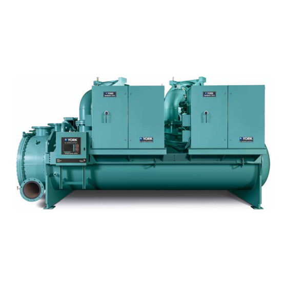
CONTROL CENTER CENTRIFUGAL LIQUID CHILLERS
Brand:
York
| Category:
Chiller
| Size: 6.84 MB
Table of Contents
Table of Contents
5
FIGURE 1 - Model YD Chiller
9
Compressor Starting
10
Compressor Shutdown
13
Section 1 - Description of System and Fundamentals of Operation
9
System Operation Description
9
FIGURE 2 - Chiller Operation Flow Chart
15
Section 2 - Optiview Control Center
23
Introduction
23
FIGURE 3 - Optiview™ Control Center
25
FIGURE 4 - Home Screen
30
FIGURE 5 - System Screen
33
Evaporator Screen
35
FIGURE 6 - Evaporator Screen
35
Condenser Screen
38
FIGURE 7 - Condenser Screen
38
FIGURE 8 - Refrigerant Level Control Screen
40
Refrigerant Level Control Screen
40
FIGURE 9 - Main Compressor Screen
42
Main Compressor Screen
42
Compressor 1 or 2 Screen
44
FIGURE 10 - Compressor 1 Screen
44
FIGURE 11 - Proximity Probe Calibration Screen
46
Proximity Probe Calibration Screen
46
FIGURE 12 - Pre-Rotation Vanes Calibration Screen
48
Pre-Rotation Vanes Calibration Screen
48
FIGURE 13 - Variable Geometry Diffuser 1 Screen
50
Variable Geometry Diffuser (VGD) Screen
50
FIGURE 14 - Variable Geometry Diffuser Setpoints Screen
52
Variable Geometry Diffuser (VGD) Setpoints Screen
52
FIGURE 15 - Variable Geometry Diffuser 1 Calibration Screen
55
Variable Geometry Diffuser (VGD) Calibration Screen
55
FIGURE 16 - Hot Gas Bypass Screen
56
Hot Gas Bypass Screen
56
FIGURE 17 - Surge Protection Screen
58
Surge Protection Screen
58
FIGURE 18 - Surge Protection Screen (Single Compressor Operation)
60
Surge Protection Screen (Single-Compressor Operation)
60
FIGURE 19 - Surge Protection Screen (Dual Compressor Operation)
63
Surge Protection Screen (Dual-Compressor Operation)
63
Capacity Control Screen
65
FIGURE 20 - Capacity Control Screen
65
Capacity Control Setpoints Screen
68
FIGURE 21 - Capacity Control Setpoints Screen
68
Anti-Surge Tuning Screen
69
FIGURE 22 - Anti-Surge Tuning Screen
69
Capacity Compressor Cycling Screen
70
FIGURE 23 - Capacity Compressor Cycling Screen
70
FIGURE 24 - Oil Sump Screen
74
Oil Sump Screen
74
FIGURE 25 - Oil Pump 1 Screen
76
Oil Pump 1 and 2 Screen
76
FIGURE 26 - Motor Starter Screen
78
Motor Starter Screen
78
FIGURE 27 - Low Voltage Variable Speed Drive Screen
80
Low Voltage Variable Speed Drive Screen
80
FIGURE 28 - Medium Voltage Variable Speed Drive Screen
82
Medium Voltage Variable Speed Drive Screen
82
FIGURE 29 - Motor Lubrication Screen
84
Motor Lubrication Screen
84
FIGURE 30 - Variable Speed Drive (VSD) Details Screen
87
Variable Speed Drive (VSD) Details Screen
87
FIGURE 31 - Harmonic Filter Details Screen
89
Harmonic Filter Details Screen
89
FIGURE 32 - Motor Details Screen
91
Motor Details Screen
91
Electro-Mechanical Starter Screen
93
FIGURE 33 - Electro-Mechanical Starter Screen
93
FIGURE 34 - Setpoints Screen
96
Setpoints Screen
96
FIGURE 35 - Setup Screen
99
Setup Screen
99
FIGURE 36 - Schedule Screen
101
Schedule Screen
101
FIGURE 37 - User Screen
103
User Screen
103
Comms Screen
105
FIGURE 38 - Comms Screen
105
FIGURE 39 - Printer Screen
106
Printer Screen
106
FIGURE 40 - Sales Order Screen
108
Sales Order Screen
108
FIGURE 41 - Operations Screen
110
Operations Screen
110
FIGURE 42 - History Screen
112
History Screen
112
FIGURE 43 - History Details Page
114
History Details Screen
114
FIGURE 44 - Security Log Screen
115
Security Log Screen
115
FIGURE 45 - Security Log Screen
116
Security Log Details Screen
116
Custom View Screen
117
FIGURE 46 - Custom View Screen
117
Custom View Setup
118
FIGURE 47 - Custom View Setup Screen
118
FIGURE 48 - Trend Screen
119
Trend Screen
119
FIGURE 49 - Trend Setup Screen
121
Trend Setup Screen
121
Advanced Trend Setup Screen
123
FIGURE 50 - Advanced Trend Setup Screen
123
Common Slots Screen
125
FIGURE 51 - Common Slots Screen
125
Slot Numbers
126
Display Messages
128
Start Inhibit Messages
129
System Screen
33
Optiview Control Center in Detail
25
Overview of Interface
26
Analog Input Ranges
29
Home Screen
30
Section 3 - Printers
147
Printing Overview
147
Control Center Setup
147
Downloading System Prints to Alaptop
147
FIGURE 52 - Communications Block Diagram
149
FIGURE 53 - Optiview Panel to PC Serial Cable
149
FIGURE 54 - Sample Printout (Status)
150
FIGURE 55 - Sample Printout (Setpoints)
152
FIGURE 56 - Sample Printout (Schedule)
154
FIGURE 57 - Sample Printout (Sales Order)
154
FIGURE 58 - Sample Printout (History)
156
FIGURE 59 - Sample Printout (Security Log Report)
158
FIGURE 60 - Sample Printout (Trend Data New or Existing Points)
158
FIGURE 61 - Sample Printout (Custom Screen Report)
158
Advertisement
Advertisement
Related Products
York OPTIVIEW YIA D
York OPTIVIEW
York OPTIVIEW YK
York 160.87-OM1
York 21RT-47RT
York 371-01200-010
York 371-01200-011
York 371-01200-015
York CodePak YK L1 L1 G4
York CodePak YK S2 S2 J4
York Categories
Air Conditioner
Heat Pump
Chiller
Furnace
Air Handlers
More York Manuals
Login
Sign In
OR
Sign in with Facebook
Sign in with Google
Upload manual
Upload from disk
Upload from URL