
Related Manuals for York YCIV


Summary of Contents for York YCIV
- Page 1 FORM 201.23-EG2 (713) Model YCIV Air-Cooled Screw Liquid Chillers with Variable Speed Drive Style A 527 - 1354 kWi 2, 3, and 4 Compressor 140-200 Tons 50Hz 60Hz HFC-134a...
-
Page 2: Table Of Contents
FORM 201.23-EG2 (713) Table of Contents Introduction ........................................... 3 Unit Overview........................................4 Accessories and Options ....................................7 Nomenclature........................................9 Temperatures and Flows ....................................10 Water Pressure Drop ......................................12 Standard Efficiency Ratings - SI - 400V/50Hz ..............................14 High Efficiency Ratings - SI - 400V/50Hz ................................. 18 Physical Data (SI - Standard Efficiency)................................ -
Page 3: Introduction
– evenings and weekends. With the introduction of the YCIV model air-cooled chiller, system designers have the opportunity to design around the traditional benefits of air-cooled chillers and still offer building owners the most up-to-date energy-efficient system design. -
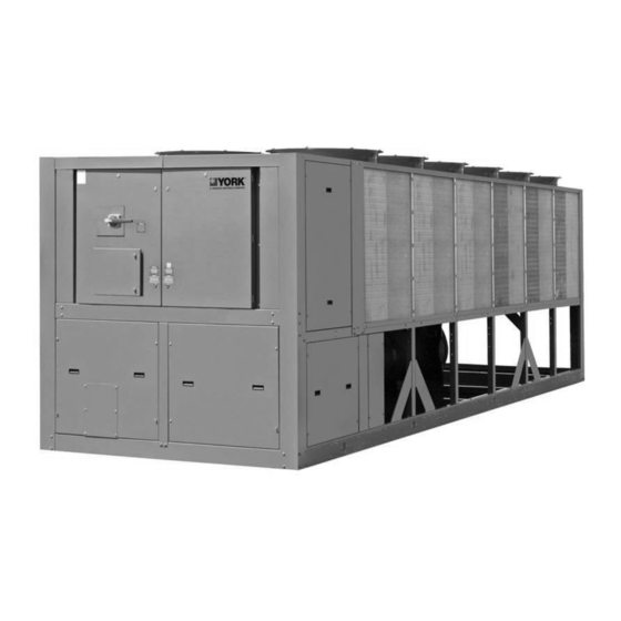
Page 4: Unit Overview
• All controls and motor starting equipment necessary SEMI-HERMETIC YORK TWIN SCREW COMPRES- for unit operation shall be factory wired and function SORS tested. Johnson Controls Engineered Systems’ Chiller Design • VSD Power/Control Panel includes main power Team has developed a world class compressor with connection(s), VSD and fan motor contactors, cur- unequaled performance: rent overloads, and factory wiring. Standard design... - Page 5 FORM 201.23-EG2 (713) • Discharge line provided with manual compressor • The fan motors are the high efficiency, direct drive, 6 shutoff service valve (See Options and Accessories for pole on standard sound models and 8 pole on reduced suction line valve). Suction line equipped with closed- and low sound models, 3 phase, Class-“F”, current cell insulation. overload protected, totally enclosed (TEAO) type with double sealed, permanently lubricated, ball bearings • Insulated external oil separators with no moving parts, 31 barg (450 psig) design working pressure, and UL • Fin and tube condenser coils constructed of seamless, listing. Refrigerant system differential pressure pro- internally enhanced, high condensing coefficient, cor- vides oil flow through service replaceable, 0.5 micron, rosion resistant copper tubes arranged in staggered full flow, cartridge type oil filter internal to compressor.
- Page 6 • Design is IAW ASHRAE 90.1 Energy Standard for parameters and maintains the maximum cooling output Building except Low-Rise Residential Buildings and possible without shutdown of the equipment: motor AHRI 70 Sound Rating of Large Outdoor Refrigeration current, suction pressure and discharge pressure. and Air Conditioning Equipment. • System Safeties are provided for individual compres- • YCIV chillers are designed within EN ISO 9001 and sor systems to perform auto-reset shut down (manual built within an EN ISO 9002 accredited manufacturing reset required after the third trip in 90 minutes). Safe- organization. ties include: high discharge pressure or temperature, • All exposed power wiring routed through liquid-tight, low suction pressure, high/low motor current, high UV-stabilized, non-metallic conduit.
-
Page 7: Accessories And Options
(This is not recommended for units in values than conventional air-cooled chillers. Over 99% areas where they may be exposed to acid rain.) of chiller operating hours occur when building loads are less than design and/or ambient temperatures are less than design. As a result, all YCIV model chillers will PROTECTIVE CHILLER PANELS: operate with less than full load sound output nearly all the time – this is especially important on evenings and • Wire Panels (full unit) – UV stabilized black polyvi- weekends when neighbors are home the most. Due to... - Page 8 FORM 201.23-EG2 (713) Accessories and Options sides of the unit to visually screen and protect coils. (Factory-mounted) SERVICE ISOLATION VALVE – Service suction isolation valve added to unit for each refrigerant circuit. (Factory- • Louvered Panels (full unit) – Louvered panels, mounted) painted the same color as the unit, enclose the unit to protect condenser coils from incidental damage, CHICAGO CODE RELIEF VALVE - Special relief valves visually screen internal components, and prevent per Chicago code. (Factory-mounted) unauthorized access to internal components. (Fac- tory-mounted)
-
Page 9: Nomenclature
FORM 201.23-EG2 (713) Nomenclature NOMENCLATURE The Model Number denotes the following characteristics of the unit: 0760 JOHNSON CONTROLS... -
Page 10: Temperatures And Flows
FORM 201.23-EG2 (713) Temperatures and Flows TEMPERATURE AND FLOWS (SI Units) LEAVING WATER COOLER FLOW AIR ON CONDENSER (°C) MODEL TEMPERATURE (°C) (L/S) NUMBER YCIV MIN. MAX. MIN. MAX. MIN. 50 HZ 15.6 42.6 -17.8 51.7 0600(S/P) 15.6 10.1 47.3 -17.8... - Page 11 FORM 201.23-EG2 (713) TEMPERATURE AND FLOWS (SI Units) LEAVING WATER COOLER FLOW AIR ON CONDENSER (°C) MODEL TEMPERATURE (°C) (L/S) NUMBER YCIV MIN. MAX. MIN. MAX. MIN. 50 HZ 15.6 11.4 50.5 -17.8 51.7 0920(S/P) 15.6 10.1 47.3 -17.8 51.7 0930(E/V) 15.6...
-
Page 12: Water Pressure Drop
FORM 201.23-EG2 (713) Water Pressure Drop SI UNITS MODEL NUMBER YCIV COOLER 50Hz 0600(S/P) 0590(E/V) 0630(E/V), 0650(S/P) 0700(E/V), 0720(S/P) 0760(E/V) 0800(E/V) 0830(E/V) 0770(S/P) 0840(S/P) 0920(S/P), 0930(E/V) 1000(S/P) JOHNSON CONTROLS... - Page 13 FORM 201.23-EG2 (713) SI UNITS Pressure Drop Through Three and Four Circuit YCIV Evaporators YCIV MODELS EVAP 50Hz 1050(E/V) 1070(S/P) 1120(E/V) 1180(S/P) 1220(E/V) 1340(S/P) 1380(E/V) 1500(S/P) 1649(P) JOHNSON CONTROLS...
-
Page 14: Standard Efficiency Ratings - Si - 400V/50Hz
699.5 232.6 648.9 248.4 616.4 235.6 13.0 790.7 169.9 776.9 191.0 760.7 215.3 715.3 233.0 660.2 246.2 621.8 229.7 NOTES: 1. kWo Unit kW Cooling Capacity Output 2. kWi Compressor kW Input 3. COP Coefficient of Performance (includes condenser fan power) 4. LCWT = Leaving Chilled Water Temperature 5. Ratings based on 0.168 l/s cooler water per ton, and 0.018 (m – °C)/kW 6. AHRI 550/590 does not provide certification for 50Hz ratings. The unique use of the YCIV variable speed drive allows compressor operation at the output speed regardless of the input power frequency. This allows for common unit/heat exchanger configurations between 60Hz and 50Hz with closely matching capacity. JOHNSON CONTROLS... - Page 15 901.1 294.0 820.0 296.6 775.2 279.1 13.0 1017.2 217.0 998.6 243.9 976.9 274.2 922.2 294.7 826.9 289.0 780.9 272.0 NOTES: 1. kWo Unit kW Cooling Capacity Output 2. kWi Compressor kW Input 3. COP Coefficient of Performance (includes condenser fan power) 4. LCWT = Leaving Chilled Water Temperature 5. Ratings based on 0.168 l/s cooler water per ton, and 0.018 (m – °C)/kW 6. AHRI 550/590 does not provide certification for 50Hz ratings. The unique use of the YCIV variable speed drive allows compressor operation at the output speed regardless of the input power frequency. This allows for common unit/heat exchanger configurations between 60Hz and 50Hz with closely matching capacity. JOHNSON CONTROLS...
- Page 16 1142.1 371.0 932.2 321.0 874.2 302.6 13.0 1310.6 276.0 1284.3 308.9 1244.1 343.9 1168.3 370.5 939.9 314.3 881.4 296.1 NOTES: 1. kWo Unit kW Cooling Capacity Output 2. kWi Compressor kW Input 3. COP Coefficient of Performance (includes condenser fan power) 4. LCWT = Leaving Chilled Water Temperature 5. Ratings based on 0.168 l/s cooler water per ton, and 0.018 (m – °C)/kW 6. AHRI 550/590 does not provide certification for 50Hz ratings. The unique use of the YCIV variable speed drive allows compressor operation at the output speed regardless of the input power frequency. This allows for common unit/heat exchanger configurations between 60Hz and 50Hz with closely matching capacity. JOHNSON CONTROLS...
- Page 17 1,675.8 559.7 1,632.0 607.8 1,614.5 615.4 13.0 1,889.8 431.2 1,858.8 481.2 1,799.1 524.4 1,715.2 565.5 1,669.4 611.3 1,651.5 618.7 NOTES: 1. kWo Unit kW Cooling Capacity Output 2. kWi Compressor kW Input 3. COP Coefficient of Performance (includes condenser fan power) 4. LCWT = Leaving Chilled Water Temperature 5. Ratings based on 0.168 l/s cooler water per ton, and 0.018 (m – °C)/kW 6. AHRI 550/590 does not provide certification for 50Hz ratings. The unique use of the YCIV variable speed drive allows compressor operation at the output speed regardless of the input power frequency. This allows for common unit/heat exchanger configurations between 60Hz and 50Hz with closely matching capacity. JOHNSON CONTROLS...
-
Page 18: High Efficiency Ratings - Si - 400V/50Hz
695.7 214.0 647.8 229.7 632.7 229.6 13.0 767.7 153.7 756.9 172.4 742.9 194.5 712.8 214.4 663.1 229.9 638.4 224.0 NOTES: 1. kWo Unit kW Cooling Capacity Output 2. kWi Compressor kW Input 3. COP Coefficient of Performance (includes condenser fan power) 4. LCWT = Leaving Chilled Water Temperature 5. Ratings based on 0.168 l/s cooler water per ton, and 0.018 (m – °C)/kW 6. AHRI 550/590 does not provide certification for 50Hz ratings. The unique use of the YCIV variable speed drive allows compressor operation at the output speed regardless of the input power frequency. This allows for common unit/heat exchanger configurations between 60Hz and 50Hz with closely matching capacity. JOHNSON CONTROLS... - Page 19 839.3 254.9 807.6 275.3 797.4 278.4 13.0 920.3 182.6 906.1 203.6 889.1 228.7 858.7 255.0 826.3 275.2 815.9 278.3 NOTES: 1. kWo Unit kW Cooling Capacity Output 2. kWi Compressor kW Input 3. COP Coefficient of Performance (includes condenser fan power) 4. LCWT = Leaving Chilled Water Temperature 5. Ratings based on 0.168 l/s cooler water per ton, and 0.018 (m – °C)/kW 6. AHRI 550/590 does not provide certification for 50Hz ratings. The unique use of the YCIV variable speed drive allows compressor operation at the output speed regardless of the input power frequency. This allows for common unit/heat exchanger configurations between 60Hz and 50Hz with closely matching capacity. JOHNSON CONTROLS...
- Page 20 1109.5 340.9 1027.4 361.6 1011.0 365.5 13.0 1238.7 245.7 1217.3 272.4 1191.4 307.2 1135.6 340.4 1051.7 360.9 1034.9 364.8 NOTES: 1. kWo Unit kW Cooling Capacity Output 2. kWi Compressor kW Input 3. COP Coefficient of Performance (includes condenser fan power) 4. LCWT = Leaving Chilled Water Temperature 5. Ratings based on 0.168 l/s cooler water per ton, and 0.018 (m – °C)/kW 6. AHRI 550/590 does not provide certification for 50Hz ratings. The unique use of the YCIV variable speed drive allows compressor operation at the output speed regardless of the input power frequency. This allows for common unit/heat exchanger configurations between 60Hz and 50Hz with closely matching capacity. JOHNSON CONTROLS...
- Page 21 1372.9 427.0 1290.1 458.2 1226.3 435.1 13.0 1525.2 311.0 1499.4 348.1 1467.3 389.3 1406.5 428.4 1308.1 450.8 1236.0 424.3 NOTES: 1. kWo Unit kW Cooling Capacity Output 2. kWi Compressor kW Input 3. COP Coefficient of Performance (includes condenser fan power) 4. LCWT = Leaving Chilled Water Temperature 5. Ratings based on 0.168 l/s cooler water per ton, and 0.018 (m – °C)/kW 6. AHRI 550/590 does not provide certification for 50Hz ratings. The unique use of the YCIV variable speed drive allows compressor operation at the output speed regardless of the input power frequency. This allows for common unit/heat exchanger configurations between 60Hz and 50Hz with closely matching capacity. JOHNSON CONTROLS...
-
Page 22: Physical Data (Si - Standard Efficiency)
FORM 201.23-EG2 (713) Physical Data (SI - Standard Efficiency) STANDARD EFFICIENCY REFRIGERANT R-134A MODEL NUMBER (YCIV____ S/P) 50HZ 0600 0650 0720 0770 0840 0920 1000 NUMBER OF INDEPENDENT REFRIGERANT CIRCUITS REFRIGERANT CHARGE, R-134A, CKT.-1/CKT.-2, KG. 74/74 77/77 84/77 87/80 87/87 105/89 105/105 OIL CHARGE, CKT.-1/CKT.-2, LITERS 19/19 19/19 19/19... - Page 23 FORM 201.23-EG2 (713) STANDARD EFFICIENCY REFRIGERANT R-134A MODEL NUMBER (YCIV____ S/P) 50HZ 1070 1180 1340 1500 1649 NUMBER OF INDEPENDENT REFRIGERANT CIRCUITS 84 / 77 / 77 84 / 84 / 77 84 / 84 / 105 105 / 105 / 105 142/142/137/137 REFRIGERANT CHARGE, R-134A, CKT.-1/CKT.-2, KG.
-
Page 24: Physical Data (Si - High Efficiency)
FORM 201.23-EG2 (713) Physical Data (SI - High Efficiency) HIGH EFFICIENCY REFRIGERANT R-134A MODEL NUMBER (YCIV____ E/V) 50HZ 0590 0630 0700 0760 0800 0830 0930 NUMBER OF INDEPENDENT REFRIGERANT CIRCUITS REFRIGERANT CHARGE, R-134A, CKT.-1/CKT.-2, KG. 77/77 84/77 84/84 87/87 102/87 102/102 105/105 OIL CHARGE, CKT.-1/CKT.-2, LITERS 19/19 19/19 19/19... - Page 25 FORM 201.23-EG2 (713) HIGH EFFICIENCY REFRIGERANT R-134A MODEL NUMBER (YCIV____ E/V) 50HZ 1050 1120 1220 1380 NUMBER OF INDEPENDENT REFRIGERANT CIRCUITS REFRIGERANT CHARGE, R-134A, CKT.-1/CKT.-2, KG. 84 / 84 / 77 84 / 84 / 105 84 / 84 / 105 105 / 105 / 105 OIL CHARGE, CKT.-1/CKT.-2, LITERS 19 / 19 / 15 19 / 19 / 19...
-
Page 26: Dimensions
FORM 201.23-EG2 (713) Dimensions YCIV0590E/V and YCIV0600S/P YCIV 2146 2865 0590E/V 2286 2797 0600S/P Notes: 1. Placement on a level surface free of obstructions (including snow, for winter operation) or air recirculation ensures rated performance, reliable operation, and ease of maintenance. Site restrictions may compromise minimum clearances indicated below, resulting in unpre- dictable air patters and possible diminished performance. - Page 27 FORM 201.23-EG2 (713) JOHNSON CONTROLS...
- Page 28 FORM 201.23-EG2 (713) Dimensions YCIV0630E/V, YCIV0650S/P, YCIV0700E/V and YCIV0720S/P YCIV 2238 6960 06307E/V 2032 5842 0650S/P 2238 6960 0700E/V 2238 6960 0720S/P Notes: 1. Placement on a level surface free of obstructions (including snow, for winter operation) or air recirculation ensures rated performance, reliable operation, and ease of maintenance. Site restrictions may compromise minimum clearances indicated below, resulting in unpre- dictable air patters and possible diminished performance.
- Page 29 FORM 201.23-EG2 (713) JOHNSON CONTROLS...
- Page 30 FORM 201.23-EG2 (713) Dimensions YCIV0760E/V, YCIV0770S/P, and YCIV0890S/P YCIV 2174 2852 0760E/V 2009 2878 0770S/P 2009 2878 0890S/P Notes: 1. Placement on a level surface free of obstructions (including snow, for winter operation) or air recirculation ensures rated performance, reliable operation, and ease of maintenance. Site restrictions may compromise minimum clearances indicated below, resulting in unpre- dictable air patters and possible diminished performance.
- Page 31 FORM 201.23-EG2 (713) JOHNSON CONTROLS...
- Page 32 FORM 201.23-EG2 (713) Dimensions YCIV0800E/V and YCIV0830E/V Notes: 1. Placement on a level surface free of obstructions (including snow, for winter operation) or air recirculation ensures rated performance, reliable operation, and ease of maintenance. Site restrictions may compromise minimum clearances indicated below, resulting in unpre- dictable air patters and possible diminished performance.
- Page 33 FORM 201.23-EG2 (713) JOHNSON CONTROLS...
- Page 34 FORM 201.23-EG2 (713) Dimensions YCIV0920S/P, YCIV0930E/V, and YCIV1000S/P Notes: 1. Placement on a level surface free of obstructions (including snow, for winter operation) or air recirculation ensures rated performance, reliable operation, and ease of maintenance. Site restrictions may compromise minimum clearances indicated below, resulting in unpre- dictable air patters and possible diminished performance.
- Page 35 FORM 201.23-EG2 (713) JOHNSON CONTROLS...
- Page 36 FORM 201.23-EG2 (713) Dimensions YCIV1050E/V and YCIV1070S/P Notes: 1. Placement on a level surface free of obstructions (including snow, for winter operation) or air recirculation ensures rated performance, reliable operation, and ease of maintenance. Site restrictions may compromise minimum clearances indicated below, resulting in unpre- dictable air patters and possible diminished performance.
- Page 37 FORM 201.23-EG2 (713) JOHNSON CONTROLS...
- Page 38 FORM 201.23-EG2 (713) Dimensions YCIV1120E/V Notes: 1. Placement on a level surface free of obstructions (including snow, for winter operation) or air recirculation ensures rated performance, reliable operation, and ease of maintenance. Site restrictions may compromise minimum clearances indicated below, resulting in unpre- dictable air patters and possible diminished performance.
- Page 39 FORM 201.23-EG2 (713) JOHNSON CONTROLS...
- Page 40 FORM 201.23-EG2 (713) Dimensions YCIV1180S/P Notes: 1. Placement on a level surface free of obstructions (including snow, for winter operation) or air recirculation ensures rated performance, reliable operation, and ease of maintenance. Site restrictions may compromise minimum clearances indicated below, resulting in unpre- dictable air patters and possible diminished performance.
- Page 41 FORM 201.23-EG2 (713) JOHNSON CONTROLS...
- Page 42 FORM 201.23-EG2 (713) Dimensions YCIV1220E/V and YCIV1340S/P Notes: 1. Placement on a level surface free of obstructions (including snow, for winter operation) or air recirculation ensures rated performance, reliable operation, and ease of maintenance. Site restrictions may compromise minimum clearances indicated below, resulting in unpre- dictable air patters and possible diminished performance.
- Page 43 FORM 201.23-EG2 (713) JOHNSON CONTROLS...
- Page 44 FORM 201.23-EG2 (713) Dimensions YCIV1380E/V and YCIV1500S/P Notes: 1. Placement on a level surface free of obstructions (including snow, for winter operation) or air recirculation ensures rated performance, reliable operation, and ease of maintenance. Site restrictions may compromise minimum clearances indicated below, resulting in unpre- dictable air patters and possible diminished performance.
- Page 45 FORM 201.23-EG2 (713) JOHNSON CONTROLS...
- Page 46 FORM 201.23-EG2 (713) Dimensions Models YCIV1649P Notes: 1. Placement on a level surface free of obstructions (including snow, for winter operation) or air recirculation ensures rated performance, reliable operation, and ease of maintenance. Site restrictions may compromise minimum clearances indicated below, resulting in unpre- dictable air patters and possible diminished performance.
- Page 47 FORM 201.23-EG2 (713) JOHNSON CONTROLS...
-
Page 48: Isolator Locations
FORM 201.23-EG2 (713) Isolator Locations STANDARD EFFICIENCY - SI MODEL YCIV ISOLATOR LOCATIONS ( X , Y ) - MM AND POINT LOADS - KG 50 HZ LEFT - L ( 230 , 2204 ) ( 1510 , 2204 ) ( 2780 , 2204 ) ( 5360 , 2204 ) AL FIN COILS CU FIN COILS RS&LS1 / AL FIN COILS... - Page 49 FORM 201.23-EG2 (713) STANDARD EFFICIENCY - SI MODEL YCIV ISOLATOR LOCATIONS ( X , Y ) - MM AND POINT LOADS - KG 50 HZ LEFT - L ( 230 , 2204 ) ( 1510 , 2204 ) ( 2470 , 2204 ) ( 4100 , 2204 ) ( 5350 , 2204 )
- Page 50 FORM 201.23-EG2 (713) Isolator Locations - SI HIGH EFFICIENCY - SI MODEL YCIV ISOLATOR LOCATIONS ( X , Y ) - MM AND POINT LOADS - KG 50 HZ LEFT - L ( 230 , 2204 ) ( 1510 , 2204 ) ( 2780 , 2204 ) ( 5360 , 2204 ) AL FIN COILS CU FIN COILS RS&LS1 / AL FIN COILS...
- Page 51 FORM 201.23-EG2 (713) HIGH EFFICIENCY - SI MODEL YCIV ISOLATOR LOCATIONS ( X , Y ) - MM AND POINT LOADS - KG 50 HZ LEFT - L ( 230 , 2204 ) ( 1510 , 2204 ) ( 2470 , 2204 ) ( 4100 , 2204 ) ( 5350 , 2204 )
-
Page 52: Isolator Details
FORM 201.23-EG2 (713) Isolator Details ONE INCH DEFLECTION SPRING ISOLATOR CROSS-REFERENCE CPX-X- 5/8" EQUIPMENT BASE (by Others H" C" T" B" L" D" W" MOUNT DIMENSION DATA (INCHES) TYPE 7-3/4 6-1/2 4-3/4 5-5/8 10-1/2 9-1/4 7-3/4 9/16 RATED CAPACITY (FOR UNITS WITH ALL LOAD POINTS LESS THAN 1785 LBS (810 KG) MODEL NUMBER COLOR CODE... - Page 53 FORM 201.23-EG2 (713) ELASTOMERIC ISOLATOR CROSS-REFERENCE RD-Style Isolators MOLDED DURULENE MOLDED DURULENE Ø = AD Thru Typ 2 Places R = 0.280 Slot Typ 2 Places LD17304 DIMENSION DATA (INCHES) MOUNT TYPE 5/16-18 UNC RD1-WR 3.13 1.75 1.25 2.38 0.34 0.19 1.25 X 3/4 RD2-WR...
- Page 54 FORM 201.23-EG2 (713) Isolator Details TWO INCH DEFLECTION, SEISMIC SPRING ISOLATOR CROSS-REFERENCE Y2RS 1-1/8” 5/8” 2-3/4” 2-3/4” 3/8” GAP 3/4” TYP. (4) 3/4” 7/8” STOP & 8-3/8” OPER. HEIGHT MODEL Y2RSI-2D SEISMICALLY RESTRAINED VIBRATION ISOLATOR FOR 2" DEFLECTION MODEL NUMBER ISOL.
- Page 55 FORM 201.23-EG2 (713) INTENTIONALLY LEFT BLANK JOHNSON CONTROLS...
-
Page 56: Electrical Data - 2 Comp Standard Efficiency
STD. & ULTRA QUIET COND. HIGH HEAD/STATIC COND. FANS TWO-SPEED COND. FANS FANS COMPRES- CONDENSER FANS CONDENSER FANS CONDENSER FANS COMPRES- COMPRES- INPUT INPUT YCIV S/P VOLTS (9) FREQ QTY. FLA (EA) RLA (5) QTY. FLA (EA) QTY. FLA (EA) RLA (5) RLA (5) - Page 57 FORM 201.23-EG2 (713) STANDARD EFFICIENCY YCIV_ _ _ _ S/P SYSTEM 2 STD. & ULTRA QUIET COND. FANS HIGH HEAD/STATIC COND. FANS TWO-SPEED COND. FANS CONDENSER FANS CONDENSER FANS CONDENSER FANS COMPRES- COMPRES- COMPRES- QTY. FLA (EA) QTY. FLA (EA) QTY. FLA (EA) RLA (5) RLA (5) RLA (5) HIGH HEAD/HIGH STATIC FANS TWO-SPEED COND.
-
Page 58: Electrical Data - 2 Comp High Efficiency
STD. & ULTRA QUIET COND. HIGH HEAD/STATIC COND. FANS TWO-SPEED COND. FANS FANS COMPRES- COMPRES- COMPRES- CONDENSER FANS CONDENSER FANS CONDENSER FANS INPUT INPUT YCIV E/V VOLTS (9) FREQ RLA (5) QTY. FLA (EA) RLA (5) QTY. FLA (EA) RLA (5) QTY. FLA (EA) - Page 59 FORM 201.23-EG2 (713) HIGH EFFICIENCY YCIV_ _ _ _ E/V SYSTEM 2 STD. & ULTRA QUIET COND. FANS HIGH HEAD/STATIC COND. FANS TWO-SPEED COND. FANS COMPRES- CONDENSER COMPRES- CONDENSER COMPRES- CONDENSER FANS FANS FANS RLA (5) QTY. FLA (EA) RLA (5) QTY. FLA (EA) RLA (5) QTY. FLA (EA) HIGH HEAD/HIGH STATIC FANS TWO-SPEED COND.
-
Page 60: Electrical Data - 3 & 4 Comp Standard Efficiency
COND. FANS FANS COND. FANS COND. FANS FANS INPUT COMP. COND. FANS COMP. COND. FANS COMP. COND. FANS COMP. COND. FANS COMP. COND. FANS COMP. COND. FANS YCIV INPUT VOLTS FREQ RLA (5) QTY. RLA (5) QTY. RLA (5) QTY. - Page 61 FORM 201.23-EG2 (713) SYSTEM 3 SYSTEM 4 STD. & ULTRA QUIET HIGH HEAD/STATIC TWO-SPEED COND. STD & ULTRA QUIET HIGH HEAD/STATIC TWO-SPEED COND COND. FANS COND. FANS FANS COND FANS COND. FANS FANS COMP. COND. FANS COMP. COND. FANS COMP. COND. FANS COMP COND. FANS COMP. COND. FANS COMP COND. FANS QTY.
-
Page 62: Electrical Data - 3 Comp High Efficiency
CONDENSER CONDENSER CONDENSER CONDENSER COMP. COMP. COMP. COMP. INPUT FANS FANS FANS FANS INPUT YCIV E/V VOLTS FREQ RLA (5) QTY. FLA (EA) RLA (5) QTY. FLA (EA) RLA (5) QTY. FLA (EA) RLA (5) QTY. FLA (EA) 1050 1120 1220 1380 FIELD WIRING &... - Page 63 FORM 201.23-EG2 (713) SYSTEM 2 SYSTEM 3 HIGH HEAD/STATIC COND. STD. & ULTRA QUIET HIGH HEAD/STATIC COND. TWO-SPEED COND. FANS TWO-SPEED COND. FANS FANS COND. FANS FANS CON- CON- CONDENSER CONDENSER CONDENSER COMP. COMP. COMP. DENSER COMP. DENSER COMP. FANS FANS FANS FANS FANS RLA (5) QTY.
-
Page 64: Electrical Notes
1. As standard, all 2 and 3 compressor units have single point power connections. The YCIV0457PA/ YCIV1649PA has dual point power connection as standard. Contact factory for information regarding dual point power 2 and 3 compressor units. 2. Maximum Inverse Time Circuit Breaker or Dual Element Fuse - 225% of the largest compressor RLA plus the sum of all other loads per NEC 440.22 (A). 3. MCA - Minimum Circuit Ampacity - 125% of the largest compressor RLA plus 100% of the remaining compressor RLA's plus the sum of all condenser fan FLA's per NEC 440.33 4. Recommended time delay or dual element fuse size - 150%of the largest compressor RLA plus 100% of the remaining compressor RLA's plus the sum of all condenser fan FLA's. 5. RLA - Rated Load Amps - rated in accordance with UL standard 1995. 6. Local codes may take precedence. 7. Control KVA includes operational controls and evaporator heaters. 8. System inrush current is less than RLA due to the use of York Variable Speed Drive technology. Typical Compressor Starting Current ( first four seconds of startup): Rated Voltage Typical Starting Current per Compressor 380-400/50/3 380/60/3 460/60/3 9. Voltage Utilization Range: Rated Voltage Utilization Range 380-415/50/3 360 - 440 380/60/3... -
Page 65: Power Wiring
FORM 201.23-EG2 (713) Power Wiring 2 COMPRESSOR POWER WIRING CONNECTIONS FIG. 1 – TWO COMPRESSOR WIRING DIAGRAM WITH CIRCUIT BREAKER FIG. 2 – TWO COMPRESSOR WIRING DIAGRAM WITH TERMINAL BLOCK JOHNSON CONTROLS... - Page 66 FORM 201.23-EG2 (713) Power Wiring 3 COMPRESSOR POWER WIRING CONNECTIONS VSD CONTROL PANEL STANDARD UNIT CONTROLS CONTROL TRANSFORMER EVAPORATOR HEATER CONTACTORS LINE REACTOR CIRCUIT BREAKER See Note 3 FIELD PROVIDED UNIT POWER SUPPLY FIG. 3 – THREE COMPRESSOR WIRING DIAGRAM WITH CIRCUIT BREAKER – SINGLE POINT 3 COMPRESSOR POWER WIRING CONNECTIONS VSD CONTROL PANEL STANDARD UNIT CONTROLS...
- Page 67 FORM 201.23-EG2 (713) FIG. 7 – FOUR COMPRESSOR WIRING DIAGRAM WITH CIRCUIT BREAKER – MULTI POINT FIG. 8 – FOUR COMPRESSOR WIRING DIAGRAM WITH TERMINAL BLOCK – MULTI POINT JOHNSON CONTROLS...
-
Page 68: Typical Control Wiring - Two Compressor
FORM 201.23-EG2 (713) Typical Control Wiring - Two Compressor JOHNSON CONTROLS... - Page 69 FORM 201.23-EG2 (713) For informational purposes only. Do not attempt to tie into wiring without a proper wiring diagram. JOHNSON CONTROLS...
-
Page 70: Typical Control Wiring - Three Compressor
FORM 201.23-EG2 (713) Typical Control Wiring - Three Compressor JOHNSON CONTROLS... - Page 71 FORM 201.23-EG2 (713) For informational purposes only. Do not attempt to tie into wiring without a proper wiring diagram. JOHNSON CONTROLS...
- Page 72 FORM 201.23-EG2 (713) Typical Control Wiring - Four Compressor JOHNSON CONTROLS...
- Page 73 FORM 201.23-EG2 (713) JOHNSON CONTROLS...
-
Page 74: Application Data
FORM 201.23-EG2 (713) Application Data UNIT LOCATION Ground Locations – Units must be installed on a sub- The YCIV chillers are designed for outdoor installation. stantial base that will not settle and cause strain on the When selecting a site for installation, be guided by the refrigerant lines, resulting in possible leaks. A one-piece following requirements: concrete slab, with footers extending below the frost line, is recommended. The slab should not be tied to the main 1. Installation sites may be either on a roof or on ground building foundation as operational noise will telegraph. level. (See FOUNDATION) Mounting holes (5/8") are provided in the base rails for bolting the unit to its foundation. See DIMENSIONS for 2. Select a place having an adequate supply of fresh air location of the mounting holes. for the condensers. Recommended clearances for all units are shown on the DIMENSIONS pages. For ground installations, precautions should be taken to protect the unit from tampering by, or injury to, unauthor- 3. Avoid locations near windows or structures where ized persons. Fasteners on access panels will prevent normal operating sounds may be objectionable. -
Page 75: Guide Specifications
FORM 201.23-EG2 (713) Guide Specifications PART 1 — GENERAL D. Warranty: Manufacturer shall Warrant all equipment and material of its manufacture against defects in 1.01 SCOPE workmanship and material for a period of eighteen (18) months from date of initial start-up or date of A. The requirements of the General Conditions, Supple- availability. - Page 76 FORM 201.23-EG2 (713) Guide Specifications controls including capacity controller, control center, ential pressure shall provide oil flow through service motor starting components, and special features as replaceable, 0.5 micron, full flow, cartridge type oil filter specified herein or required for safe, automatic opera- internal to compressor. Filter bypass, less restrictive tion. media, or oil pump not acceptable. C. Operating Characteristics: D. Capacity Control: Compressors shall start at minimum load. Provide Microprocessor control to command 1. P rovide low ambient control and high ambient compressor capacity to balance compressor capacity options as required to ensure unit is capable with cooling load. When required to meet minimum of operation from 0°F to 125°F (-18°C to 52°C) load, hot gas bypass shall be factory installed and...
- Page 77 FORM 201.23-EG2 (713) alloy fins with full height collars. Subcooling coil 2. T he installing contractor is responsible for ad- an integral part of condenser. Design working ditional cost to furnish and install power factor pressure shall be 450 psig (31 barg). correction capacitors if they are not factory mounted and wired. 2. Low Sound Fans: Shall be dynamically and stati- cally balanced, direct drive, corrosion resistant G. Exposed compressor and fan motor power wiring shall glass fiber reinforced composite blades molded be routed through liquid tight conduit. into low noise, full airfoil cross section, provid- ing vertical air discharge from extended orifices. Guards of heavy gauge, PVC (polyvinyl chloride) 2.06 CONTROLS coated or galvanized steel.
- Page 78 FORM 201.23-EG2 (713) Guide Specifications data for last ten shutdown faults. Compressor suc- b. Two-speed fans and acousticallly lined enclo- tion, discharge, and oil pressures and temperatures, sure. (Factory Mounted) suction and discharge superheats, percent of full-load, c. Sound power octave band data, dB per AHRI operating hours, starts, and anti-recycle timer status. standard 70 and IAW ISO3744 at 35°C ambi- Status Messages for manual override, unit switch off, ent and 7°C leaving chilled water. compressor run, run permissive, remote controlled shut down, no cooling load, daily/holiday shut down, 2. P rovide optional control input to limit sound out- anti-recycle timer. put of the chiller based on time of day. Shall be programmable at the chiller panel or controlled E. Predictive Control Points: Unit controls shall avoid remotely via signal (4-20mA or 0-10 VDC) from safety shutdown when operating outside design con- BAS system. Chillers without this feature shall...
- Page 79 FORM 201.23-EG2 (713) unit panels. Heavy gauge, welded wire-mesh, 3. 2" Deflection Seismic Isolators: Level adjust- coated to resist corrosion, around base of ma- able, restrained mounts in rugged welded steel chine to restrict unauthorized access. housing with vertical and horizontal limit stops. Housings shall be designed to withstand a mini- mum 1.0g accelerated force in all directions to E. Evaporator options: 2” (50.8 mm). 1. Provide 1-1/2” (38mm) cooler insulation in lieu of standard 3/4” (19mm). J. Service Shut-Off Valve: Provide suction service shut-off 2. Provide Raised Face Flanges for cooler nozzles: valve for each compressor. (Factory Mounted) a. 150 psig (10.3 barg), welded flanges (field kit, matching pipe flange by contractor). PART 3 — EXECUTION b. 150 psig (10.3 barg) companion flanges. (not available with 460V units) 3.01 INSTALLATION c. 150 psig (10.3 barg), ANSI/AWWA C-606 A. General: Rig and Install in full accordance with couplings (field kit, matching pipe flange by Manufacturer’s requirements, Project drawings, and...
- Page 80 Form 201.23-EG2 (713) New Release...