York YMC2 Operation And Maintenance
Centrifugal liquid chillers with r-134a or r-513a refrigerant
Hide thumbs
Also See for YMC2:
- Installation and assembly manual (74 pages) ,
- Manual (71 pages) ,
- Manual (8 pages)

Related Manuals for York YMC2


Summary of Contents for York YMC2
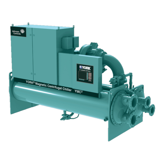
- Page 1 CENTRIFUGAL LIQUID CHILLERS WITH R-134A OR R-513A REFRIGERANT OPERATIONS AND MAINTENANCE Supersedes: 160.84-OM1 (717) Form 160.84-OM1 (917) MODEL B WITH OPTIVIEW™ CONTROL CENTER LD17500 Issue Date: September 21, 2017...
- Page 2 FORM 160.84-OM1 ISSUE DATE: 9/21/2017 IMPORTANT! READ BEFORE PROCEEDING! GENERAL SAFETY GUIDELINES This equipment is a relatively complicated apparatus. which it is situated, as well as severe personal injury or During rigging, installation, operation, maintenance, death to themselves and people at the site. or service, individuals may be exposed to certain com- This document is intended for use by owner-authorized ponents or conditions including, but not limited to:...
- Page 3 FORM 160.84-OM1 ISSUE DATE: 9/21/2017 CHANGEABILITY OF THIS DOCUMENT In complying with Johnson Controls’ policy for contin- these documents, the technician should verify whether uous product improvement, the information contained the equipment has been modified and if current litera- in this document is subject to change without notice. ture is available from the owner of the equipment prior Johnson Controls makes no commitment to update or to performing any work on the chiller.
- Page 4 FORM 160.84-OM1 ISSUE DATE: 9/21/2017 SYSTEM NOMENCLATURE Y M C 2 - S 0756 A B YORK Mod Level A = Refrigerant R-134a Magnetic Bearing B = Refrigerant R-513a Centrifugal Chiller Capacity in KW S = Single Stage T = Two Stage...
- Page 5 FORM 160.84-OM1 ISSUE DATE: 9/21/2017 VARIABLE SPEED DRIVE NOMENCLATURE HYP 0730 X H C 15 D - 40A Amps 40 = 400V 60Hz 0490, 0612, 0730, 0774, 1278 40 = 380V 60Hz 50 = 400V 50Hz X = Factory Mount 50 = 380V 60Hz R = Retrofit Model 42 = 400V 60Hz...
-
Page 6: Table Of Contents
FORM 160.84-OM1 ISSUE DATE: 9/21/2017 TABLE OF CONTENTS SECTION 1 - SYSTEM FUNDAMENTALS ......................11 System Components ............................11 System Operation Description ........................15 SECTION 2 - SYSTEM OPERATING PROCEDURES ...................19 Pre-Starting ..............................19 Condenser Water Temperature Control ......................19 Start-Up ................................ - Page 7 FORM 160.84-OM1 ISSUE DATE: 9/21/2017 TABLE OF CONTENTS (CONT'D) SECTION 6 - PRINTING ............................133 Printing Overview ............................133 Acceptable Printers ............................133 Printer Connections ............................134 Printer Setup ..............................134 Printer Connections ............................135 Control Center Setup ............................ 135 Downloading System Prints to a Laptop ...................... 136 Temperature ..............................
- Page 8 FORM 160.84-OM1 ISSUE DATE: 9/21/2017 LIST OF FIGURES FIGURE 1 - YMC Chiller Components ........................9 FIGURE 2 - Optiview™ Control Center ........................11 FIGURE 3 - Refrigerant Flow-Thru Chiller.......................16 FIGURE 4 - Liquid Chiller Log Sheets ........................20 FIGURE 5 - Home Screen ............................28 FIGURE 6 - System Screen ............................30 FIGURE 7 - Evaporator Screen ..........................32 FIGURE 8 - Condenser Screen ..........................34...
- Page 9 FORM 160.84-OM1 ISSUE DATE: 9/21/2017 LIST OF FIGURES (CONT'D) FIGURE 55 - Sample Printout (Schedule) ......................140 FIGURE 56 - Sample Printout (Sales Order)......................140 FIGURE 57 - Sample Printout (Security Log Report) ....................142 FIGURE 58 - Sample Printout (Trend Data New or Existing Points) ..............142 FIGURE 59 - Sample Printout (Custom Screen Report) ..................142 LIST OF TABLES TABLE 1 - Input Current Limit Threshold ........................18...
- Page 10 FORM 160.84-OM1 ISSUE DATE: 9/21/2017 THIS PAGE INTENTIONALLY LEFT BLANK. JOHNSON CONTROLS...
-
Page 11: Section 1 - System Fundamentals
ISSUE DATE: 9/21/2017 SECTION 1 - SYSTEM FUNDAMENTALS SYSTEM COMPONENTS The motor includes angular contact ball bearings only The YORK Model YMC Centrifugal Liquid Chiller engaged with the rotor shaft during shutdown after is completely factory-packaged including evapora- rotation is stopped or during shutdown due to loss of tor, condenser, compressor, motor, Variable Speed power to the magnetic bearings. - Page 12 FORM 160.84-OM1 SECTION 1 - SYSTEM FUNDAMENTALS ISSUE DATE: 9/21/2017 glass is located on the side of the shell. The evapora- While the chiller is running, the refrigerant level is nor- tor shell contains dual refrigerant relief valves unless mally controlled to the level setpoint. condenser isolation is installed.
-
Page 13: Figure 2 - Optiview™ Control Center
The Decimal key provides accurate entry of OptiView Control Center setpoint values. The YORK OptiView™ control center LCD Graphic Display and keypad is the interface for starting, stop- A +/- key has also been provided to allow entry ± ping, configuring, monitoring, and commanding the of negative values and AM/PM selection dur- chiller controls. - Page 14 24-hour performance monitoring via a remote site. An cling shutdown. optional circuit board called the SC-EQUIP provides Johnson Controls and YORK mechanical equipment If the chiller is Stopped and the Condenser Pump con- such as the YMC chiller with building automation tacts are open (flow off), the contacts close when Satu- system (BAS) networking connectivity.
-
Page 15: System Operation Description
FORM 160.84-OM1 SECTION 1 - SYSTEM FUNDAMENTALS ISSUE DATE: 9/21/2017 The chiller operating program resides in the Opti- Capacity Control View Control Center microboard. Software versions The major components of a chiller are selected to (C.OPT.18.xx.yzz) are alpha-numeric codes that rep- handle the required refrigerant flow at full load design resent the application, language package and revision conditions. - Page 16 FORM 160.84-OM1 SECTION 1 - SYSTEM FUNDAMENTALS ISSUE DATE: 9/21/2017 The YMC Chiller controls capacity by adjusting the rary conditions. Also, this feature allows the Leaving compressor VGD position, the compressor motor Vari- Chilled Liquid Temperature Setpoint to be set as low as able Speed Drive (VSD), and optional Hot Gas Bypass 36.0ºF (2.2ºC).
- Page 17 FORM 160.84-OM1 SECTION 1 - SYSTEM FUNDAMENTALS ISSUE DATE: 9/21/2017 Head Pressure Control The Head Pressure Control feature enables chiller control of a field-mounted facility condenser water temperature control means, if one is necessary for pro- longed cold water startup as described in SECTION 3 - OPTIVIEW™...
-
Page 18: Figure 3 - Refrigerant Flow-Thru Chiller
High Pressure Vapor High Pressure Liquid Refrigerant Low Pressure Liquid Refrigerant Low Pressure Vapor OPTIONAL HOT COMPRESSOR GAS BYPASS VALVE DISCHARGE LINE CONTROL PANEL SUCTION YORK ® MAGNETIC CENTRIFUGAL CHILLER SYSTEM DATA LINE PLATE POWER 029-26550-000 REV- PANEL ISOLATION VALVE... -
Page 19: Section 2 - System Operating Procedures
CONDENSER WATER TEMPERATURE CONTROL drive coolant temperature, fail-closed, and set for a temperature above dewpoint. It can The YORK YMC chiller is designed to use less power be requested as factory-supplied on a chiller by taking advantage of lower than design temperatures order by special quotation. -
Page 20: Chiller Operation
FORM 160.84-OM1 SECTION 2 - SYSTEM OPERATING PROCEDURES ISSUE DATE: 9/21/2017 CHILLER OPERATION TABLE 1 - INPUT CURRENT LIMIT THRESHOLD CONTROL ACTIVE INPUT CURRENT Upon start request, the following occur in sequence: SOURCE LIMIT THRESHOLD 1. Chiller's system pump run contacts close Lowest of: Local Local Input Current Limit Setpoint (% Input Job FLA) -
Page 21: Operator Setpoints Quick Reference
FORM 160.84-OM1 SECTION 2 - SYSTEM OPERATING PROCEDURES ISSUE DATE: 9/21/2017 Regardless of which method is used to select the de- OPERATOR SETPOINTS QUICK REFERENCE sired Leaving Chilled Liquid Temperature (LCHLT), The most common Operator level setpoints can be the chiller controls to its own Active LCHLT Setpoint. found on the Setpoints screen or the following screens: The Active Setpoint is a target to the programmed setpoint. -
Page 22: Safety Stop
FORM 160.84-OM1 SECTION 2 - SYSTEM OPERATING PROCEDURES ISSUE DATE: 9/21/2017 SAFETY STOP When depressed, the chiller will not run under any An accurate record of readings serves as a valuable condition. For safety reasons, this position is required reference for operating the system. Readings taken for many maintenance tasks to be completed. -
Page 23: Prolonged Shutdown
FORM 160.84-OM1 SECTION 2 - SYSTEM OPERATING PROCEDURES ISSUE DATE: 9/21/2017 PROLONGED SHUTDOWN If the chiller is to be shut down for an extended period 3. On the SETUP Screen, disable the clock. This of time (for example, over the winter season), the fol- conserves the battery. -
Page 24: Table 3 - Water Flow Rate Limits In Gpm (L/S)-Based Upon Standard Tubes @ Design Full Load Conditions
FORM 160.84-OM1 SECTION 2 - SYSTEM OPERATING PROCEDURES ISSUE DATE: 9/21/2017 TABLE 3 - WATER FLOW RATE LIMITS IN GPM (L/S) – BASED UPON STANDARD TUBES @ DESIGN FULL LOAD CONDITIONS EVAPORATOR CONDENSER EVAPORATOR CONDENSER 1 PASS 2 PASS 3 PASS 1 PASS 2 PASS 3 PASS... - Page 25 FORM 160.84-OM1 SECTION 2 - SYSTEM OPERATING PROCEDURES ISSUE DATE: 9/21/2017 TABLE 3 - WATER FLOW RATE LIMITS IN GPM (L/S) – BASED UPON STANDARD TUBES @ DESIGN FULL LOAD CONDITIONS (CONT'D) EVAPORATOR CONDENSER EVAPORATOR CONDENSER 1 PASS 2 PASS 3 PASS 1 PASS 2 PASS...
- Page 26 FORM 160.84-OM1 SECTION 2 - SYSTEM OPERATING PROCEDURES ISSUE DATE: 9/21/2017 TABLE 3 - WATER FLOW RATE LIMITS IN GPM (L/S) – BASED UPON STANDARD TUBES @ DESIGN FULL LOAD CONDITIONS (CONT'D) EVAPORATOR CONDENSER EVAPORATOR CONDENSER 1 PASS 2 PASS 3 PASS 1 PASS 2 PASS...
-
Page 27: Section 3 - Optiview™ Control Center Functions And Navigation
FORM 160.84-OM1 ISSUE DATE: 9/21/2017 SECTION 3 - OPTIVIEW™ CONTROL CENTER FUNCTIONS AND NAVIGATION INTERFACE CONVENTIONS to change all of the setpoints required to operate the Each screen description in this document will begin chiller system. In order to gain standard OPERATOR with a section entitled Overview which will describe level access, the Home Screen Login Password would the graphical elements on the screen and give a short... - Page 28 FORM 160.84-OM1 SECTION 3 - OPTIVIEW™ CONTROL CENTER FUNCTIONS AND NAVIGATION ISSUE DATE: 9/21/2017 2. If the dialog box begins with the word “ENTER”, The system will immediately refresh the display with use the numeric keys to enter the desired value. the graphics for that screen.
-
Page 29: Analog Input Ranges
FORM 160.84-OM1 SECTION 3 - OPTIVIEW™ CONTROL CENTER FUNCTIONS AND NAVIGATION ISSUE DATE: 9/21/2017 LANGUAGES The screens can be displayed in various languages. guage. If a language other than English is being dis- Language selection is done on the USER Screen. The played, an English speaking person should navigate desired language is selected from those available. -
Page 30: Figure 5 - Home Screen
FORM 160.84-OM1 SECTION 3 - OPTIVIEW™ CONTROL CENTER FUNCTIONS AND NAVIGATION ISSUE DATE: 9/21/2017 HOME SCREEN LD17916a FIGURE 5 - HOME SCREEN OVERVIEW Input % Full Load Amps This displays the percentage of full load amps utilized When the chiller system is powered on, the above de- by the system. - Page 31 FORM 160.84-OM1 SECTION 3 - OPTIVIEW™ CONTROL CENTER FUNCTIONS AND NAVIGATION ISSUE DATE: 9/21/2017 Print NAVIGATION Access Level Required: VIEW System Use this key to generate a hard-copy report of the Used to provide additional system information. present system status. This provides a snapshot of the primary operating conditions at the time the key is Evaporator pressed.
-
Page 32: Figure 6 - System Screen
FORM 160.84-OM1 SECTION 3 - OPTIVIEW™ CONTROL CENTER FUNCTIONS AND NAVIGATION ISSUE DATE: 9/21/2017 SYSTEM SCREEN LD17917a FIGURE 6 - SYSTEM SCREEN OVERVIEW Condenser Liquid Temperature - Entering Displays the temperature of the liquid as it enters the This screen gives a general overview of common chill- condenser. - Page 33 FORM 160.84-OM1 SECTION 3 - OPTIVIEW™ CONTROL CENTER FUNCTIONS AND NAVIGATION ISSUE DATE: 9/21/2017 Evaporator Pressure PROGRAMMABLE Displays the present refrigerant pressure in the evapo- There are no programmable fields on this screen. rator. Evaporator Saturation Temperature NAVIGATION Displays the present saturation temperature in the Home evaporator calculated from evaporator pressure.
-
Page 34: Figure 7 - Evaporator Screen
FORM 160.84-OM1 SECTION 3 - OPTIVIEW™ CONTROL CENTER FUNCTIONS AND NAVIGATION ISSUE DATE: 9/21/2017 EVAPORATOR SCREEN LD17918a FIGURE 7 - EVAPORATOR SCREEN OVERVIEW Evaporator Pressure Displays the present refrigerant pressure in the evapo- This screen displays a cutaway view of the chiller rator. - Page 35 FORM 160.84-OM1 SECTION 3 - OPTIVIEW™ CONTROL CENTER FUNCTIONS AND NAVIGATION ISSUE DATE: 9/21/2017 Leaving Chilled Liquid Temperature Setpoints Local Leaving Chilled Liquid Temperature - – Remote Range Range Access Level Required: OPERATOR Displays the temperature range proportional to a re- mote analog input used to reset the Leaving Chilled This is the range over which an analog or a digital sig- nal (PWM) can reset the Leaving Chilled Liquid Tem-...
-
Page 36: Figure 8 - Condenser Screen
FORM 160.84-OM1 SECTION 3 - OPTIVIEW™ CONTROL CENTER FUNCTIONS AND NAVIGATION ISSUE DATE: 9/21/2017 CONDENSER SCREEN LD17919a FIGURE 8 - CONDENSER SCREEN OVERVIEW Condenser Small Temperature Difference Displays the difference between the Condenser Refrig- This screen displays a cutaway view of the chiller con- erant temperature and the Leaving Condenser Liquid denser. - Page 37 FORM 160.84-OM1 SECTION 3 - OPTIVIEW™ CONTROL CENTER FUNCTIONS AND NAVIGATION ISSUE DATE: 9/21/2017 Condenser Liquid Flow Switch NAVIGATION Indicates whether flow is present in the condenser. Home Causes an instant return to the Home Screen. Condenser Liquid Pump (Run/Stop) Displays the command presently sent by the control center to the Condenser Liquid Pump run contacts.
-
Page 38: Figure 9 - Heat Pump Screen
All setpoints pertinent to this feature are maintained on Heat Pump is an available option on certain models of this screen. YMC2 chillers. The feature is enabled and disabled on the SETUP Screen (Service level required). When en- DISPLAY ONLY abled, this HEAT PUMP Screen is accessible from the CONDENSER and the EVAPORATOR Screen. - Page 39 FORM 160.84-OM1 SECTION 3 - OPTIVIEW™ CONTROL CENTER FUNCTIONS AND NAVIGATION ISSUE DATE: 9/21/2017 ture Setpoint in Heating mode. See the Leaving Con- PROGRAMMABLE denser Liquid Temperature Setpoint – Range Setpoint Unit Control Mode description below. Access Level Required: OPERATOR Leaving Condenser Liquid Temperature This setpoint can only be changed when the chiller is Setpoints –...
- Page 40 FORM 160.84-OM1 SECTION 3 - OPTIVIEW™ CONTROL CENTER FUNCTIONS AND NAVIGATION ISSUE DATE: 9/21/2017 Leaving Condenser Liquid Temperature Cy- Heating LCHLT Shutdown cling Offset – Shutdown Access Level Required: OPERATOR Access Level Required: OPERATOR In Heating mode, the existing LEAVING CHILLED This setpoint allows the user to specify the Leaving LIQUID TEMPERATURE –...
-
Page 41: Figure 10 - Compressor Screen
FORM 160.84-OM1 SECTION 3 - OPTIVIEW™ CONTROL CENTER FUNCTIONS AND NAVIGATION ISSUE DATE: 9/21/2017 COMPRESSOR SCREEN LD17922a FIGURE 10 - COMPRESSOR SCREEN OVERVIEW Input % Full Load Amps Displays the chiller current as a percentage of the job This screen displays a cutaway view of the chiller com- input Full Load Amps (FLA) value. - Page 42 FORM 160.84-OM1 SECTION 3 - OPTIVIEW™ CONTROL CENTER FUNCTIONS AND NAVIGATION ISSUE DATE: 9/21/2017 Motor Details Moves to the subscreen allowing view of the Magnetic Moves to the screen showing motor operating details. Bearing Controller parameters and event log. Power Panel Surge Moves to the subscreen that allows viewing power Moves to the subscreen that allows viewing and pro-...
-
Page 43: Figure 11 - Magnetic Bearing Controller Screen
FORM 160.84-OM1 SECTION 3 - OPTIVIEW™ CONTROL CENTER FUNCTIONS AND NAVIGATION ISSUE DATE: 9/21/2017 MAGNETIC BEARING CONTROLLER SCREEN LD17923a FIGURE 11 - MAGNETIC BEARING CONTROLLER SCREEN OVERVIEW W3 (Current) Displays the magnetizing current to the lower bearing This screen displays the orientation of the magnetic on the radial axis designated “W”... - Page 44 FORM 160.84-OM1 SECTION 3 - OPTIVIEW™ CONTROL CENTER FUNCTIONS AND NAVIGATION ISSUE DATE: 9/21/2017 W24 Position [MBC Outputs] MBC Alive (LED) Displays the shaft position in micrometers from center Indicates the MBC Alive allowed contacts are closed along the radial axis designated “W” for the Opposite by the control Digital Input.
-
Page 45: Figure 12 - Magnetic Bearing Controller Details Screen
FORM 160.84-OM1 SECTION 3 - OPTIVIEW™ CONTROL CENTER FUNCTIONS AND NAVIGATION ISSUE DATE: 9/21/2017 MAGNETIC BEARING CONTROLLER DETAILS SCREEN LD17924a FIGURE 12 - MAGNETIC BEARING CONTROLLER DETAILS SCREEN OVERVIEW Z2 Temperature Displays the temperature measured at the opposite im- This screen displays the orientation of the magnetic peller end bearing assembly. - Page 46 FORM 160.84-OM1 SECTION 3 - OPTIVIEW™ CONTROL CENTER FUNCTIONS AND NAVIGATION ISSUE DATE: 9/21/2017 [MBC Status] AVR (LED) PROGRAMMABLE Indicates the MBC is reporting its automatic vibration There are no programmable fields on this screen. reduction feature is active via Modbus Data. [MBC Status] ABS (LED) NAVIGATION Indicates the MBC is reporting its automatic balancing...
-
Page 47: Figure 13 - Surge Screen
FORM 160.84-OM1 SECTION 3 - OPTIVIEW™ CONTROL CENTER FUNCTIONS AND NAVIGATION ISSUE DATE: 9/21/2017 SURGE SCREEN LD17927a FIGURE 13 - SURGE SCREEN OVERVIEW This screen displays the chiller compressor and all pa- discarded and the number of surge events in the most rameters relating to the Surge Protection feature. - Page 48 FORM 160.84-OM1 SECTION 3 - OPTIVIEW™ CONTROL CENTER FUNCTIONS AND NAVIGATION ISSUE DATE: 9/21/2017 PROGRAMMABLE NAVIGATION Shutdown (Enabled/Disabled) Home Access Level Required: OPERATOR Causes an instant return to the Home Screen. Allows the user to select whether the chiller will shut- Compressor down or continue to run when an Excess Surge situa- tion has been detected.
-
Page 49: Figure 14 - Variable Geometry Diffuser Screen
FORM 160.84-OM1 SECTION 3 - OPTIVIEW™ CONTROL CENTER FUNCTIONS AND NAVIGATION ISSUE DATE: 9/21/2017 VARIABLE GEOMETRY DIFFUSER SCREEN LD17928a FIGURE 14 - VARIABLE GEOMETRY DIFFUSER SCREEN OVERVIEW VGD Command This screen displays information pertinent to the VGD Displays the position command from the control to operation. -
Page 50: Figure 15 - Power Panel Screen
FORM 160.84-OM1 SECTION 3 - OPTIVIEW™ CONTROL CENTER FUNCTIONS AND NAVIGATION ISSUE DATE: 9/21/2017 POWER PANEL SCREEN LD17930a FIGURE 15 - POWER PANEL SCREEN OVERVIEW UPS Inverter (LED) Indicates the UPS is providing power from the storage This screen displays information pertaining to the battery. - Page 51 Access Level Required: Operator Initiates a battery load test. Only applies when chiller is shutdown and manual operation of power supply to the chiller can be performed according to the pro- cess outlines in YORK YMC Service Manual (Form 160.84-M2). JOHNSON CONTROLS...
-
Page 52: Figure 16 - Capacity Controls Screen
FORM 160.84-OM1 SECTION 3 - OPTIVIEW™ CONTROL CENTER FUNCTIONS AND NAVIGATION ISSUE DATE: 9/21/2017 CAPACITY CONTROL SCREEN LD17931a FIGURE 16 - CAPACITY CONTROLS SCREEN OVERVIEW Input Current % FLA Displays the percent of useful job full load current This screen displays the pertinent parameters associat- presently supplied to the chiller, determined from the ed with capacity control in relation to Leaving Chilled highest of the three phase Input Currents/(Input Job... - Page 53 FORM 160.84-OM1 SECTION 3 - OPTIVIEW™ CONTROL CENTER FUNCTIONS AND NAVIGATION ISSUE DATE: 9/21/2017 Leaving Chilled Liquid • Inactive – Capacity Control is not active Displays the temperature of the chilled liquid as it leaves the evaporator. • None – No limit is in effect Active LCHLT Setpoint • Input Current Displays the active temperature setpoint to which the...
-
Page 54: Figure 17 - Variable Speed Drive Screen
FORM 160.84-OM1 SECTION 3 - OPTIVIEW™ CONTROL CENTER FUNCTIONS AND NAVIGATION ISSUE DATE: 9/21/2017 VARIABLE SPEED DRIVE SCREEN LD17932a FIGURE 17 - VARIABLE SPEED DRIVE SCREEN OVERVIEW in Digital Remote mode, SC-Equip Gateway interface This screen displays information pertaining to the Vari- in BAS (ISN) mode, or a locally programmed value. - Page 55 FORM 160.84-OM1 SECTION 3 - OPTIVIEW™ CONTROL CENTER FUNCTIONS AND NAVIGATION ISSUE DATE: 9/21/2017 Output Current (RMS) - Phase A, B, C Pulldown Demand Limit Displays the RMS current measured to the motor, per Access Level Required: OPERATOR Allows the user to specify the current limit value (as a phase.
-
Page 56: Figure 18 - Variable Speed Drive (Vsd) Details Screen
FORM 160.84-OM1 SECTION 3 - OPTIVIEW™ CONTROL CENTER FUNCTIONS AND NAVIGATION ISSUE DATE: 9/21/2017 VARIABLE SPEED DRIVE (VSD) DETAILS SCREEN LD17933a FIGURE 18 - VARIABLE SPEED DRIVE (VSD) DETAILS SCREEN • 1 = Precharge OVERVIEW • 2 = Pre-Regulate This screen displays more detailed parameters associ- ated with the Variable Speed Drive. - Page 57 FORM 160.84-OM1 SECTION 3 - OPTIVIEW™ CONTROL CENTER FUNCTIONS AND NAVIGATION ISSUE DATE: 9/21/2017 VSD Output Frequency Input Current RMS (L1, L2, L3) Displays the present output frequency to the motor. Displays the three-phase input current values measured by the VSD. Phase Rotation Output Voltage RMS (Phase A, B, C) Displays the phase rotation sequencing...
-
Page 58: Figure 19 - Motor Details Screen
FORM 160.84-OM1 SECTION 3 - OPTIVIEW™ CONTROL CENTER FUNCTIONS AND NAVIGATION ISSUE DATE: 9/21/2017 MOTOR DETAILS SCREEN LD17934a FIGURE 19 - MOTOR DETAILS SCREEN OVERVIEW VGD Position Displays the present variable geometry diffuser posi- This screen displays information pertinent to the Motor tion as a value between 0% (closed) and 100% (full Temperature Monitoring feature. - Page 59 FORM 160.84-OM1 SECTION 3 - OPTIVIEW™ CONTROL CENTER FUNCTIONS AND NAVIGATION ISSUE DATE: 9/21/2017 Rotor Elongation Motor Cooling Valve Command Displays the calculated change in distance from the Output to the motor cooling valve in percent from 0% two axial position sensors for the rotor shaft versus (closed) to 100% Opened) the shutdown baseline set at the factory.
-
Page 60: Figure 20 - Setpoints Screen
FORM 160.84-OM1 SECTION 3 - OPTIVIEW™ CONTROL CENTER FUNCTIONS AND NAVIGATION ISSUE DATE: 9/21/2017 SETPOINTS SCREEN LD17935a FIGURE 20 - SETPOINTS SCREEN OVERVIEW Input Current Limit Setpoint Displays the active Input Current Limit setpoint. This This screen provides a convenient location for pro- is the minimum of the locally or remote (received via gramming the most common setpoints involved in the 0-10VDC, 2-10VDC, 0-20mA or 4-20mA input or... - Page 61 FORM 160.84-OM1 SECTION 3 - OPTIVIEW™ CONTROL CENTER FUNCTIONS AND NAVIGATION ISSUE DATE: 9/21/2017 Local Leaving Chilled Liquid Temperature - Local Input Current Limit Setpoint Access Level Required: OPERATOR Access Level Required: OPERATOR Allows the user to specify the maximum allowed chill- This value allows the user to define the Leaving er input current (as a percentage of FLA).
-
Page 62: Figure 21 - Setup Screen
A qualified Service Technician, follow- month, and four-digit year (using leading zeroes as ing instructions in YORK YMC Service Manual (Form necessary). If within range, the value will be accepted. - Page 63 Moves to the subscreen allowing definition of the pump control contacts (I/O Board TB2-44/45) opera- chiller operation schedule. tion as either Standard or Enhanced. Service Techni- cians refer to YORK YMC Service Manual (Form User 160.84-M2). Access Level Required: OPERATOR...
- Page 64 FORM 160.84-OM1 SECTION 3 - OPTIVIEW™ CONTROL CENTER FUNCTIONS AND NAVIGATION ISSUE DATE: 9/21/2017 Comms Access Level Required: OPERATOR Moves to the subscreen allowing configuration of sys- tem communications. Printer Moves to the subscreen allowing configuration and control of printer functions. Sales Order Moves to the subscreen displaying the Sales Order in- formation for the chiller system.
-
Page 65: Figure 22 - Schedule Screen
FORM 160.84-OM1 SECTION 3 - OPTIVIEW™ CONTROL CENTER FUNCTIONS AND NAVIGATION ISSUE DATE: 9/21/2017 SCHEDULE SCREEN LD17937a FIGURE 22 - SCHEDULE SCREEN OVERVIEW The user has the ability to define a standard set of Start The schedule screen contains more programmable val- / Stop times which are utilized every week. - Page 66 FORM 160.84-OM1 SECTION 3 - OPTIVIEW™ CONTROL CENTER FUNCTIONS AND NAVIGATION ISSUE DATE: 9/21/2017 Exception Start/Stop Times Reset All Exception Days Access Level Required: OPERATOR Access Level Required: OPERATOR For each day of the week, the user may specify a time Deletes all programming for exception days within the for the chiller to start and a time for the chiller to stop.
-
Page 67: Figure 23 - User Screen
FORM 160.84-OM1 SECTION 3 - OPTIVIEW™ CONTROL CENTER FUNCTIONS AND NAVIGATION ISSUE DATE: 9/21/2017 USER SCREEN LD17938a FIGURE 23 - USER SCREEN OVERVIEW the list of those available. English is the Default lan- This screen allows definition of custom User ID’s and matching passwords. -
Page 68: Figure 24 - Comms Screen
FORM 160.84-OM1 SECTION 3 - OPTIVIEW™ CONTROL CENTER FUNCTIONS AND NAVIGATION ISSUE DATE: 9/21/2017 COMMS SCREEN LD17939a FIGURE 24 - COMMS SCREEN OVERVIEW This screen allows definition of the necessary commu- to be changed. With the selection box around the de- nications parameters. -
Page 69: Figure 25 - Printer Screen
FORM 160.84-OM1 SECTION 3 - OPTIVIEW™ CONTROL CENTER FUNCTIONS AND NAVIGATION ISSUE DATE: 9/21/2017 PRINTER SCREEN LD17940a FIGURE 25 - PRINTER SCREEN OVERVIEW Printer Type Access Level Required: OPERATOR This screen allows definition of the necessary commu- Define the printer type connected to the chiller system. nications parameters for the printer. - Page 70 Service Technician. Entry instructions are included in the YORK YMC Service Manual (Form 160.84-M2). Condenser Model The remainder of the values are entered at the YORK Factory defined model number of the Condenser. Factory during the manufacturing of the chiller. VSD Model DISPLAY ONLY Factory defined model number of the VSD.
- Page 71 FORM 160.84-OM1 SECTION 3 - OPTIVIEW™ CONTROL CENTER FUNCTIONS AND NAVIGATION ISSUE DATE: 9/21/2017 Commissioning Date NAVIGATION Define the date at which the chiller was commissioned. Home Causes an instant return to the Home Screen. Job Name and Location Factory defined job name and location the chiller is Setup destined for.
-
Page 72: Figure 27 - Operations Screen
FORM 160.84-OM1 SECTION 3 - OPTIVIEW™ CONTROL CENTER FUNCTIONS AND NAVIGATION ISSUE DATE: 9/21/2017 OPERATIONS SCREEN LD17942a FIGURE 27 - OPERATIONS SCREEN OVERVIEW PROGRAMMABLE This screen allows definition of general parameters Control Source having to do with the operation of the chiller. Access Level Required: OPERATOR Define whether the control of the chiller will be Local, Digital Remote, Analog Remote, Modem Remote or... -
Page 73: Figure 28 - History Screen
FORM 160.84-OM1 SECTION 3 - OPTIVIEW™ CONTROL CENTER FUNCTIONS AND NAVIGATION ISSUE DATE: 9/21/2017 HISTORY SCREEN LD17943a FIGURE 28 - HISTORY SCREEN OVERVIEW Last Fault While Running This window displays the date and time and the de- This screen allows the user to browse through the faults. scription of the last safety or cycling shutdown while In order to get a more thorough reporting of the system the system was running. - Page 74 FORM 160.84-OM1 SECTION 3 - OPTIVIEW™ CONTROL CENTER FUNCTIONS AND NAVIGATION ISSUE DATE: 9/21/2017 NAVIGATION Home Causes an instant return to the Home Screen. View Details Causes a move to a subscreen containing the value of select chiller parameters at the time of the associated shutdown.
-
Page 75: Figure 29 - History Details Screen
FORM 160.84-OM1 SECTION 3 - OPTIVIEW™ CONTROL CENTER FUNCTIONS AND NAVIGATION ISSUE DATE: 9/21/2017 HISTORY DETAILS SCREEN LD17944a FIGURE 29 - HISTORY DETAILS SCREEN OVERVIEW NAVIGATION This screen allows the user to see an on-screen printout Home of all the system parameters at the time of the selected Causes an instant return to the Home Screen. - Page 76 FORM 160.84-OM1 SECTION 3 - OPTIVIEW™ CONTROL CENTER FUNCTIONS AND NAVIGATION ISSUE DATE: 9/21/2017 CUSTOM SCREEN LD17947a FIGURE 30 - CUSTOM SCREEN OVERVIEW NAVIGATION This screen allows up to 10 Service Technician select- Home ed parameters to be displayed. These parameters are Causes an instant return to the Home Screen.
-
Page 77: Figure 31 - Custom Setup Screen
FORM 160.84-OM1 SECTION 3 - OPTIVIEW™ CONTROL CENTER FUNCTIONS AND NAVIGATION ISSUE DATE: 9/21/2017 CUSTOM SETUP SCREEN LD17948a FIGURE 31 - CUSTOM SETUP SCREEN OVERVIEW tom Slot 1. If it is desired to change an already entered This screen allows the Service technician to select up to parameter, use the 5 and 6 keys to place the selection 10 parameters for display on the Custom View Screen. -
Page 78: Figure 32 - Trend Screen
FORM 160.84-OM1 SECTION 3 - OPTIVIEW™ CONTROL CENTER FUNCTIONS AND NAVIGATION ISSUE DATE: 9/21/2017 TREND SCREEN LD17949a FIGURE 32 - TREND SCREEN OVERVIEW Similarly, if the actual value is greater than the Y-axis As many as six Operator selected parameters (data label maximum for that parameter, the value will be points) can be plotted in an X/Y graph format. - Page 79 FORM 160.84-OM1 SECTION 3 - OPTIVIEW™ CONTROL CENTER FUNCTIONS AND NAVIGATION ISSUE DATE: 9/21/2017 If a power failure occurs while the trending is running, Print the trending is stopped. Upon restoration of power, Allows the data on the trend screen to be printed in the last screen of data that was collected will be dis- tabular format.
-
Page 80: Figure 33 - Trend Setup Screen
FORM 160.84-OM1 SECTION 3 - OPTIVIEW™ CONTROL CENTER FUNCTIONS AND NAVIGATION ISSUE DATE: 9/21/2017 TREND SETUP SCREEN LD17950a FIGURE 33 - TREND SETUP SCREEN OVERVIEW Collection Interval Access Level Required: OPERATOR This screen is used to configure the trending screen. Selects the interval at which the parameters are sam- The parameters to be trended are selected from the pled. - Page 81 FORM 160.84-OM1 SECTION 3 - OPTIVIEW™ CONTROL CENTER FUNCTIONS AND NAVIGATION ISSUE DATE: 9/21/2017 1. Determine the desired time interval (in seconds), Data Point Max (1-6) between data samples. Access Level Required: OPERATOR Only displayed if the associated slot number is not 2.
-
Page 82: Figure 34 - Advanced Trend Setup Screen
FORM 160.84-OM1 SECTION 3 - OPTIVIEW™ CONTROL CENTER FUNCTIONS AND NAVIGATION ISSUE DATE: 9/21/2017 ADVANCED TREND SETUP SCREEN 00474VIP FIGURE 34 - ADVANCED TREND SETUP SCREEN OVERVIEW Entry fields are as follows: The desired data collection start/stop triggers are setup on this screen. - Page 83 FORM 160.84-OM1 SECTION 3 - OPTIVIEW™ CONTROL CENTER FUNCTIONS AND NAVIGATION ISSUE DATE: 9/21/2017 PROGRAMMABLE Primary to Secondary Operator Access Level Required: OPERATOR Primary Trigger Selects whether the Primary Trigger, Secondary Trig- Access Level Required: OPERATOR ger or both have to be true in order to start or stop data Selects the first parameter to be evaluated.
-
Page 84: Figure 35 - Common Slots Screen
FORM 160.84-OM1 SECTION 3 - OPTIVIEW™ CONTROL CENTER FUNCTIONS AND NAVIGATION ISSUE DATE: 9/21/2017 COMMON SLOTS SCREEN LD14869 FIGURE 35 - COMMON SLOTS SCREEN OVERVIEW Page Up Access Level Required: OPERATOR This screen displays the slot numbers of the commonly Scroll up in the displayed data. -
Page 85: Master Slot Numbers List For Use With Trend Feature
FORM 160.84-OM1 SECTION 3 - OPTIVIEW™ CONTROL CENTER FUNCTIONS AND NAVIGATION ISSUE DATE: 9/21/2017 MASTER SLOT NUMBERS LIST FOR USE WITH TREND FEATURE SLOT # DESCRIPTION SLOT # DESCRIPTION SYSTEM CONDENSER Chiller Operating State 2048 Leaving Condenser Liquid Temperature Coastdown Time Remaining 2049 Condenser Liquid Flow Switch Safety Relay... - Page 86 FORM 160.84-OM1 SECTION 3 - OPTIVIEW™ CONTROL CENTER FUNCTIONS AND NAVIGATION ISSUE DATE: 9/21/2017 SLOT # DESCRIPTION SLOT # DESCRIPTION 1799 Remote Modem Temperature Setpoint 3057 Precharge Complete 1800 Selected Temperature Setpoint 3027 DC Bus Voltage 1802 Remote Temperature Range 2829 Cooling System 1803...
- Page 87 FORM 160.84-OM1 SECTION 3 - OPTIVIEW™ CONTROL CENTER FUNCTIONS AND NAVIGATION ISSUE DATE: 9/21/2017 SLOT # DESCRIPTION SLOT # DESCRIPTION 18058 Head Pressure 21024 Rotor Elongation 18093 Active Anti-Surge Minimum Frequency 21025 Motor Speed 18122 VSD Frequency Command 21041 MBC Fault 18143 Input Current Override Threshold 21042...
-
Page 88: Display Messages
FORM 160.84-OM1 SECTION 3 - OPTIVIEW™ CONTROL CENTER FUNCTIONS AND NAVIGATION ISSUE DATE: 9/21/2017 DISPLAY MESSAGES The Status Bar of the Display contains a Status Line To aid in the meaning of the message, messages are and, beneath it a Details Line. The Status Line contains displayed in different colors as follows: a message describing the operating state of the chill- • Normal Operation messages - Green... -
Page 89: Table 6 - Run Messages
FORM 160.84-OM1 SECTION 3 - OPTIVIEW™ CONTROL CENTER FUNCTIONS AND NAVIGATION ISSUE DATE: 9/21/2017 TABLE 6 - RUN MESSAGES MESSAGE DESCRIPTION LEAVING CHILLED LIQUID The chiller is running, controlling the Leaving Chilled Liquid to the Leaving Chilled Liquid CONTROL Temperature Setpoint. Or if the unit is a Heatpump and the Control Mode is Cooling. The chiller is running, controlling the Leaving Condenser Liquid to the Leaving Con- LEAVING CONDENSER LIQUID denser Liquid Temperature Setpoint. -
Page 90: Table 8 - Start Inhibit Messages
The Safety threshold in Brine applications is determined by the Brine solution and is determined by the YORK Factory. While this condition is in effect, the chiller capacity control is in override to in- crease suction pressure. - Page 91 FORM 160.84-OM1 SECTION 3 - OPTIVIEW™ CONTROL CENTER FUNCTIONS AND NAVIGATION ISSUE DATE: 9/21/2017 TABLE 9 - WARNING MESSAGES MESSAGE DESCRIPTION The chiller is running greater than 30 minutes and the Subcooler Effectiveness value decreased less than 0.400 (ADMIN programmable) at any drop leg refrigerant tempera- ture or increased greater than 1.50 (ADMIN programmable) when the drop leg refriger- WARNING - LOSS OF ant temperature is at least 0.5 °F below or any amount above the Entering Condenser...
-
Page 92: Table 10 - Routine Shutdown Messages
FORM 160.84-OM1 SECTION 3 - OPTIVIEW™ CONTROL CENTER FUNCTIONS AND NAVIGATION ISSUE DATE: 9/21/2017 TABLE 9 - WARNING MESSAGES (CONT'D) MESSAGE DESCRIPTION A blank BRAM battery-backed memory device (IC location U52 on Microboard) or a failure of this device was detected during the initialization process that occurs when power is applied to the control center. -
Page 93: Table 11 - Cycling Shutdown Messages
For Brine cooling applications, the shutdown threshold varies according to the concentration of the Brine solution. The Brine shutdown threshold is programmed at the YORK Factory. It should not be changed by anyone other than a qualified Service Technician following instructions in YORK YMC Service Manual (Form 160.84-M2). - Page 94 FORM 160.84-OM1 SECTION 3 - OPTIVIEW™ CONTROL CENTER FUNCTIONS AND NAVIGATION ISSUE DATE: 9/21/2017 TABLE 11 - CYCLING SHUTDOWN MESSAGES (CONT'D) MESSAGE DESCRIPTION Valid communication between the microboard and the LTC I/O Board have been EXPANSION I/O – SERIAL disrupted for 3 consecutive attempts. The chiller will automatically restart when valid COMMUNICATIONS communication is received.
- Page 95 FORM 160.84-OM1 SECTION 3 - OPTIVIEW™ CONTROL CENTER FUNCTIONS AND NAVIGATION ISSUE DATE: 9/21/2017 TABLE 11 - CYCLING SHUTDOWN MESSAGES (CONT'D) MESSAGE DESCRIPTION The MBC has measured shaft displacement is greater than 90 µm from center in the orthogonal radial axis designated V at the opposite-impeller end radial magnetic bearing MBC –...
- Page 96 FORM 160.84-OM1 SECTION 3 - OPTIVIEW™ CONTROL CENTER FUNCTIONS AND NAVIGATION ISSUE DATE: 9/21/2017 TABLE 11 - CYCLING SHUTDOWN MESSAGES (CONT'D) MESSAGE DESCRIPTION The MBC has measured shaft displacement is greater than 100 µm axially from the design running position (approximately 1/2 of the air gap space to the touchdown bearing MBC –...
- Page 97 FORM 160.84-OM1 SECTION 3 - OPTIVIEW™ CONTROL CENTER FUNCTIONS AND NAVIGATION ISSUE DATE: 9/21/2017 TABLE 11 - CYCLING SHUTDOWN MESSAGES (CONT'D) MESSAGE DESCRIPTION If the A phase input current exceeds the value for the given model of drive, then a cycling shutdown will occur.
- Page 98 FORM 160.84-OM1 SECTION 3 - OPTIVIEW™ CONTROL CENTER FUNCTIONS AND NAVIGATION ISSUE DATE: 9/21/2017 TABLE 11 - CYCLING SHUTDOWN MESSAGES (CONT'D) MESSAGE DESCRIPTION VSD – LOGIC BOARD This shutdown is generated if a communications problem occurs between the two mi- croprocessors on the VSD Logic Board.
- Page 99 FORM 160.84-OM1 SECTION 3 - OPTIVIEW™ CONTROL CENTER FUNCTIONS AND NAVIGATION ISSUE DATE: 9/21/2017 TABLE 11 - CYCLING SHUTDOWN MESSAGES (CONT'D) MESSAGE DESCRIPTION VSD – PHASE B MOTOR GATE See “VSD – PHASE A MOTOR GATE DRIVER” message preceding. DRIVER VSD –...
-
Page 100: Table 12 - Safety Shutdown Messages
The chiller can be started after manual resets are per- Manual (Form 160.84-M2) and Chiller service (Form 160.84-M1). formed as detailed below. Service and troubleshooting information is contained in the YORK YMC2 Service MESSAGE DESCRIPTION The Auxiliary Safety shutdown input, connected to I/O Board TB4-31 senses 115 VAC, initiat- AUXILIARY SAFETY –... - Page 101 Brine solution. The Brine shut- down threshold is programmed at the YORK Factory. It should not be changed by anyone other than a qualified Service Technician following instructions in YORK YMC Service Manual (Form 160.84-M2).
- Page 102 FORM 160.84-OM1 SECTION 3 - OPTIVIEW™ CONTROL CENTER FUNCTIONS AND NAVIGATION ISSUE DATE: 9/21/2017 TABLE 12 - SAFETY SHUTDOWN MESSAGES (CONT'D) MESSAGE DESCRIPTION INTERNAL ERROR – BRAM is detected to be a size other than 512K. Clears when proper size BRAM is detected INVALID BRAM upon boot up.
- Page 103 FORM 160.84-OM1 SECTION 3 - OPTIVIEW™ CONTROL CENTER FUNCTIONS AND NAVIGATION ISSUE DATE: 9/21/2017 TABLE 12 - SAFETY SHUTDOWN MESSAGES (CONT'D) MESSAGE DESCRIPTION This Safety Shutdown is set when the MBC detects a temperature is greater than 266ºF (130ºC) on the opposite-impeller end axial magnetic bearing. The MBC Fault contacts open. The MBC MBC –...
- Page 104 CLEAR FAULTS key is pressed. This Safety Shutdown is set when the chiller initiates three MBC-STARTUP FAILURE Cycling MBC – STARTUP Shutdown in a 90 minute period. Refer to YORK YMC Service Manual (Form 160.84-M2) for FAILURE conditions necessary to complete MBC startup successfully. Check fault history details to deter- mine which specific conditions were not met.
-
Page 105: Figure 26 - Sales Order Screen
FORM 160.84-OM1 SECTION 3 - OPTIVIEW™ CONTROL CENTER FUNCTIONS AND NAVIGATION ISSUE DATE: 9/21/2017 TABLE 12 - SAFETY SHUTDOWN MESSAGES (CONT'D) MESSAGE DESCRIPTION This Safety Shutdown is set when Motor Housing Temperature is greater than or equal to 185°F MOTOR – HIGH (85°C). - Page 106 FORM 160.84-OM1 SECTION 3 - OPTIVIEW™ CONTROL CENTER FUNCTIONS AND NAVIGATION ISSUE DATE: 9/21/2017 TABLE 12 - SAFETY SHUTDOWN MESSAGES (CONT'D) MESSAGE DESCRIPTION The Microboard’s software Watchdog initiated a Microprocessor reset because it detected that a portion of the chiller operating program was not being executed. The result of this reset is WATCHDOG –...
- Page 107 FORM 160.84-OM1 SECTION 3 - OPTIVIEW™ CONTROL CENTER FUNCTIONS AND NAVIGATION ISSUE DATE: 9/21/2017 TABLE 12 - SAFETY SHUTDOWN MESSAGES (CONT'D) MESSAGE DESCRIPTION This message is generated when the sum of the 3 phases of instantaneous input current values are greater than the shutdown value for a period of 1 second for the given model of drive listed below.
- Page 108 FORM 160.84-OM1 SECTION 3 - OPTIVIEW™ CONTROL CENTER FUNCTIONS AND NAVIGATION ISSUE DATE: 9/21/2017 TABLE 12 - SAFETY SHUTDOWN MESSAGES (CONT'D) MESSAGE DESCRIPTION This shutdown indicates the input current to the VSD is not sinusoidal. This shutdown will occur if the Total Demand Distortion (TDD) exceeds 25% continuously for 45 seconds. The displayed VSD –...
- Page 109 FORM 160.84-OM1 SECTION 3 - OPTIVIEW™ CONTROL CENTER FUNCTIONS AND NAVIGATION ISSUE DATE: 9/21/2017 TABLE 12 - SAFETY SHUTDOWN MESSAGES (CONT'D) MESSAGE DESCRIPTION The 105% motor current overload value is based on the highest output current compared to the programmed Motor Current value displayed on the Control panel. The 105% motor current over- load value is 1.05 times the programmed Motor Current value displayed on the Control panel.
- Page 110 FORM 160.84-OM1 SECTION 3 - OPTIVIEW™ CONTROL CENTER FUNCTIONS AND NAVIGATION ISSUE DATE: 9/21/2017 TABLE 12 - SAFETY SHUTDOWN MESSAGES (CONT'D) MESSAGE DESCRIPTION The VSD software contains a verification process to ensure that the correct set of software is VSD – RECTIFIER installed in the VSD logic board for the application.
-
Page 111: Section 4 - Vsd Operation
In vious designs of being chiller mounted, provide for the past, YORK developed direct liquid cooling for the high levels of energy savings, great integration with inverter power modules, but today York is direct liquid... -
Page 112: Optispeed Compressor Drive Details (0490 And 0774 Amp Drives)
FORM 160.84-OM1 SECTION 4 - VSD OPERATION ISSUE DATE: 9/21/2017 The new Bus capacitor is the core of the power unit. that it appears more like a sine wave. The input filter The new capacitor is made of a material that is much reduces the effects of the high frequency switching of more robust and has a longer lifetime than Bus capaci- the rectifier and provides the inductance for boosting... -
Page 113: Optispeed Compressor Drive Details (0490A, 0612A 0730A And 1278A Amp Drives)
FORM 160.84-OM1 SECTION 4 - VSD OPERATION ISSUE DATE: 9/21/2017 that the internal temperature of the OSCD does not ex- Harmonic Filter Benefits ceed a safe operation level. Three Current Transform- The OptiSpeed Compressor Drive (OSCD) system ers monitor the output current from the OSCD power now includes an input Harmonic filter and high fre- unit and are used to protect the drive and motor from quency filter trap designed to meet the IEEE Std 519,... -
Page 114: Figure 36 - Left Side Of Drive Cabinet (Typical For Most Of The Drive Models)
FORM 160.84-OM1 SECTION 4 - VSD OPERATION ISSUE DATE: 9/21/2017 Line Voltage Isolation Board Cooling Fans Circuit Breaker or Disconnect Switch Voltage Transient Board LD16294 Input Power Fuses Note: Variable Speed Drive Model HYP0774 Shown. FIGURE 36 - LEFT SIDE OF DRIVE CABINET (TYPICAL FOR MOST OF THE DRIVE MODELS) JOHNSON CONTROLS... -
Page 115: Figure 37 - Left Side Of 1278A Amp Drive Cabinet
FORM 160.84-OM1 SECTION 4 - VSD OPERATION ISSUE DATE: 9/21/2017 Cooling Fans Cooling Coil Voltage Transient Board Circuit Breaker Line Voltage Isolation Board Drive Logic Board Input Power LD21206 Fuses FIGURE 37 - LEFT SIDE OF 1278A AMP DRIVE CABINET JOHNSON CONTROLS... -
Page 116: Figure 38 - Right Side Of Drive Cabinet Hyp0490
FORM 160.84-OM1 SECTION 4 - VSD OPERATION ISSUE DATE: 9/21/2017 Power Unit Includes 3 Phases for the Rectifier and Inverter Drive Logic Board Input Filter Output Inductor LD18052 FIGURE 38 - RIGHT SIDE OF DRIVE CABINET HYP0490 Power Unit Includes 3 Phases for the Rectifier and Inverter Drive Logic... -
Page 117: Figure 40 - Right Side Of Drive Cabinet Hyp0612A
FORM 160.84-OM1 SECTION 4 - VSD OPERATION ISSUE DATE: 9/21/2017 Power Unit Includes 3 Phases for the Rectifier and Inverter Drive Logic Board Output Inductor LD18743 FIGURE 40 - RIGHT SIDE OF DRIVE CABINET HYP0612A Power Unit Includes 3 Phases for the Rectifier and Inverter Drive Logic... -
Page 118: Figure 42 - Right Side Of Drive Cabinet Hyp0774
FORM 160.84-OM1 SECTION 4 - VSD OPERATION ISSUE DATE: 9/21/2017 Phase C Power Unit Phase A Power Drive Logic Unit Board Phase B Power Unit Output Inductor Input Line Inductor LD18053 FIGURE 42 - RIGHT SIDE OF DRIVE CABINET HYP0774 Phase A Power Unit Phase C... -
Page 119: Figure 44 - Drive Logic Board
FORM 160.84-OM1 SECTION 4 - VSD OPERATION ISSUE DATE: 9/21/2017 LD16293 FIGURE 44 - DRIVE LOGIC BOARD LD18051 FIGURE 45 - RECTIFIER SIDE OF THE POWER UNIT HYP0490, HYP0490A, HYP0612A AND HYP0730A JOHNSON CONTROLS... -
Page 120: Optispeed Compressor Drive And Chiller Operation (0490 And 0774 Amp Models)
FORM 160.84-OM1 SECTION 4 - VSD OPERATION ISSUE DATE: 9/21/2017 LD16292 FIGURE 46 - RECTIFIER SIDE OF THE POWER UNIT HYP0774 AND HYP1278A OPTISPEED COMPRESSOR DRIVE AND During normal chiller run conditions the control panel CHILLER OPERATION (0490 AND 0774 AMP provides a speed command to the OSCD. -
Page 121: Optispeed Compressor Drive And Chiller Operation (0490A, 0612A, 0730A And 1278A Amp Models)
FORM 160.84-OM1 SECTION 4 - VSD OPERATION ISSUE DATE: 9/21/2017 OPTISPEED COMPRESSOR DRIVE AND CHILLER OPERATION (0490A, 0612A, 0730A AND 1278A AMP MODELS) When the chiller enters a start command, the OSCD is commanded to pre-charge, the pre-charge contactor will close and slowly charge the DC Bus capacitors through the pre-charge resistors. - Page 122 FORM 160.84-OM1 SECTION 4 - VSD OPERATION ISSUE DATE: 9/21/2017 THIS PAGE INTENTIONALLY LEFT BLANK. JOHNSON CONTROLS...
-
Page 123: Section 5 - Maintenance
This procedure must be performed at the specified time interval by an Industry Certified Technician who has been trained and qualified to work on this type of YORK equipment. A record of this procedure being successfully carried out must be maintained on file by the equipment owner should proof of adequate maintenance be required at a later date for warranty validation purposes. -
Page 124: Renewal Parts
FORM 160.84-OM1 SECTION 5 - MAINTENANCE ISSUE DATE: 9/21/2017 RENEWAL PARTS Annually (More Often If Necessary) 1. Evaporator and Condenser For any required Renewal Parts, refer to the YMC Unit Renewal Parts Manual (Form 160.84-RP1 and RP2). a. Inspect and clean water strainers OPERATING INSPECTIONS b. -
Page 125: System Evacuation
FORM 160.84-OM1 SECTION 5 - MAINTENANCE ISSUE DATE: 9/21/2017 4. To improve evacuation circulate hot water, not 4. Test around each joint and factory weld carefully to exceed 125°F (51.7ºC) through the evaporator and thoroughly. and condenser tubes to thoroughly dehydrate the 5. -
Page 126: Figure 47 - Evacuation Of Chiller
FORM 160.84-OM1 SECTION 5 - MAINTENANCE ISSUE DATE: 9/21/2017 TABLE 14 - SYSTEM PRESSURES *GAUGE ABSOLUTE BOILING INCHES OF MERCURY MILLIMETERS TEMPERATURES (HG) BELOW ONE PSIA OF MERCURY MICRONS OF WATER °F STANDARD (HG) ATMOSPHERE 0" 14.6960 760.00 760,000 10.240" 9.6290 500.00 500,000... -
Page 127: Figure 48 - Saturation Curve
FORM 160.84-OM1 SECTION 5 - MAINTENANCE ISSUE DATE: 9/21/2017 Operation Dehydration of a refrigerant system can be obtained by this method because the water present in the system reacts much as a refrigerant would. By pulling down the pressure in the system to a point where its satu- ration temperature is considerably below that of room temperature, heat will flow from the room through the walls of the system and vaporize the water, allowing... -
Page 128: Conduct Pressure Test
FORM 160.84-OM1 SECTION 5 - MAINTENANCE ISSUE DATE: 9/21/2017 CONDUCT PRESSURE TEST Refrigerant may be furnished in cylinders containing either 30, 50, 125, 1,025 or 1750 lbs. (13.6, 22.6, 56.6, If a pressure test indicates all joints are not leaking, 464 or 794 kg) of refrigerant. -
Page 129: Handling Refrigerant For Dismantling And Repairs
FORM 160.84-OM1 SECTION 5 - MAINTENANCE ISSUE DATE: 9/21/2017 HANDLING REFRIGERANT FOR DISMANTLING AND REPAIRS If it becomes necessary to open any part of the refrigerant system for repairs, it will be necessary to remove the charge before opening any part of the unit. If the chiller is equipped with optional valves, the refrigerant can be isolated in either the condenser or evaporator / compressor while making any necessary repairs. - Page 130 FORM 160.84-OM1 SECTION 5 - MAINTENANCE ISSUE DATE: 9/21/2017 1. The condenser tubes should be cleaned annually Condenser or earlier if conditions warrant. If the temperature In a condenser, trouble due to fouled tubes is usually difference between the water off the condenser indicated by a steady rise in head pressure, over a pe- and the condenser liquid temperature is more than riod of time, accompanied by a steady rise in condens-...
-
Page 131: Electrical Controls
FORM 160.84-OM1 SECTION 5 - MAINTENANCE ISSUE DATE: 9/21/2017 from the tubes with the result that a more satisfactory 3. With nitrogen or dry air, blow out the tubes to cleaning job will be accomplished with a probable sav- clear them of traces of refrigerant laden moisture ing of time. -
Page 132: Automatic Battery Health Test - During Shutdown
FORM 160.84-OM1 SECTION 5 - MAINTENANCE ISSUE DATE: 9/21/2017 AUTOMATIC BATTERY HEALTH TEST – DURING SHUTDOWN For periodic maintenance or to diagnose battery faults • If the UPS shuts down (OptiView will lose power) or warnings, a battery health test can be performed. due to voltage, fuses, disconnect, or any other rea- This test is initiated from the Power Panel screen of son the test fails and the Optiview displays a fault... -
Page 133: Section 6 - Printing
FORM 160.84-OM1 ISSUE DATE: 9/21/2017 SECTION 6 - PRINTING PRINTING OVERVIEW A printer can be connected to the Control Center’s The following figures are examples of the different Microboard to print the following reports. The screen print reports. Solid State Starter application print re- from which each report can be generated is listed in ports shown. -
Page 134: Printer Connections
FORM 160.84-OM1 SECTION 6 - PRINTING ISSUE DATE: 9/21/2017 Proceed with caution and use the following guidelines PRINTER CONNECTIONS if an unlisted printer is selected: Connect the printer to the Control Center Microboard as follows. Only one printer can be connected at a time. 1. -
Page 135: Printer Connections
FORM 160.84-OM1 SECTION 6 - PRINTING ISSUE DATE: 9/21/2017 Brecknell – CONTROL CENTER SETUP Models: Brecknell CP130 Chiller ID • Dimensions: Access Level Required: OPERATOR 5.25″ Long x 3.75″ Wide x 2.5″ High Using the COMMS Screen, assign an identification • Paper: Thermal 57mm (2.25”) number to the chiller. This number will appear at the top of each report. -
Page 136: Downloading System Prints To Alaptop
FORM 160.84-OM1 SECTION 6 - PRINTING ISSUE DATE: 9/21/2017 DOWNLOADING SYSTEM PRINTS TO A LAPTOP Downloading system histories to a file is another use- 5. Press the Print Screen key on the appropriate ful method to capture system operating conditions. The screen to be captured. -
Page 137: Figure 51 - Communications Block Diagram
FORM 160.84-OM1 SECTION 6 - PRINTING ISSUE DATE: 9/21/2017 The connector on the PC has male pins; therefore, the mating cable needs to terminate DB9/F (female pin) connector. RS-232 COM 1 MICRO HYPERTERMINAL Port 2B EQ 232 Port COM 4B OPTIVIEW SC-EQUIP LD14492A... -
Page 138: Figure 53 - Sample Printout (Status Or History)
Condenser Refrigerant Level Control ----------------------------------------------------- Status or History Condenser Refrigerant Level 7.3 % YORK History 1 (line only displayed for History Report) Condenser Active Level Setpoint 7.3 % YORK Live Data (line only displayed for Status Report) Condenser Level Control State = Inactive ¬Sales Order Job Name here... - Page 139 FORM 160.84-OM1 SECTION 6 - PRINTING ISSUE DATE: 9/21/2017 Variable Speed Drive – Fault Snapshot VGD Position = 25.00 % ------------------------------------------------------ VGD Control Mode = Auto VSD Output Voltage HGBP Command 25.0 % VSD Output Frequency 0.00 Hz (when HGBP enabled) Input Power 0 kW HGBP Control Mode...
-
Page 140: Figure 54 - Sample Printout (Setpoints)
= 2 Bits Sales Order Evaporator Model here Sales Order Condenser Model here Evaporator Sales Order VSD Model here ------------------------------------------------------ YMC2 ¬Chiller ID Leaving Chilled Local Setpoint 42.0 ~F (c) 2010 Johnson Controls Leaving Chilled ISN Setpoint 45.0 ~F Mon 01 Nov 2010... - Page 141 FORM 160.84-OM1 SECTION 6 - PRINTING ISSUE DATE: 9/21/2017 Variable Geometry Diffuser Temperature Control Max Loading Delta Temperature Control Max Unloading Delta ------------------------------------------------------ 100% VGD Counts 2000 VSD Output Gain VGD Output Gain 0% VGD Counts = 28493 VGD Feedback Calibrated = True HGBP Output Gain Max Frequency Multiplier...
- Page 142 ISSUE DATE: 9/21/2017 YORK SALES ORDER YORK SCHEDULE YMC2 ¬CHILLER ID CHILLER ID (C) 2010 JOHNSON CONTROLS © 1997 - 1999 YORK INTERNATIONAL CORPORATION MON 01 NOV 2010 9:25:18 AM MON 29 MAR 1999 1 27 PM ORDER INFORMATION SCHEDULE...
- Page 143 FORM 160.84-OM1 SECTION 6 - PRINTING ISSUE DATE: 9/21/2017 EVAPORATOR FOULING FACTOR (HR-FT-°F/BTU OR M^2-°C/KW) EVAPORATOR LIQUID TYPE EVAPORATOR BRINE PERCENT DESIGN CONDITIONS - CONDENSER ---------------------------------------------------- CONDENSER PRESSURE DROP (FT OR KPA) CONDENSER FLOW (GPM OR L/S) CONDENSER LEAVING TEMPERATURE (°F OR °C) CONDENSER ENTERING TEMPERATURE (°F OR °C) CONDENSER FOULING FACTOR (HR-FT-°F/BTU OR M^2-°C/KW) CONDENSER LIQUID TYPE...
- Page 144 YORK SETPOINT CHANGE LOG YORK TREND CHILLER ID 0 CHILLER ID 163 (c) 1997 – 2001 YORK INTERNATIONAL CORPORATION Fri 05 Oct 2001 4:48:04 PM © 1997 – 2000 YORK INTERNATIONAL CORPORATION Log Entry 1 Evaporator - Leaving Chilled Local Setpoint...
-
Page 145: Temperature
FORM 160.84-OM1 ISSUE DATE: 9/21/2017 The following factors can be used to convert from English to the most common SI Metric values. TABLE 18 - SI METRIC CONVERSION MEASUREMENT MULTIPLY ENGLISH UNIT BY FACTOR TO OBTAIN METRIC UNIT Capacity Tons Refrigerant Effect (ton) 3.516 Kilowatts (kW) Power... - Page 146 5000 Renaissance Drive, New Freedom, Pennsylvania USA 17349 800-861-1001 Subject to change without notice. Printed in USA Copyright © by Johnson Controls 2017 www.johnsoncontrols.com ALL RIGHTS RESERVED Form 160.84-OM1 (917) Issue Date: September 21, 2017 Supersedes: 160.84-OM1 (717)