Table of Contents
Advertisement
Quick Links
Air-Cooled Screw Liquid Chillers
Supersedes: 201.28-NM1.1 (321)
Form 201.28-NM1.1 (821)
Installation, Operation, Maintenance
035-23219-100
Model YVAA Style A
Air-Cooled Screw Liquid Chillers with Variable Speed Drive
Frame Sizes 015 – 052
150 ton to 500 ton
525 kW to 1750 kW
2 Compressor
50 Hz and 60 Hz
HFC-134A or R-513A
Issue Date:
August 6, 2021
Advertisement
Table of Contents

Related Manuals for York YVAA Style A


Summary of Contents for York YVAA Style A
- Page 1 Air-Cooled Screw Liquid Chillers Supersedes: 201.28-NM1.1 (321) Form 201.28-NM1.1 (821) Installation, Operation, Maintenance 035-23219-100 Model YVAA Style A Air-Cooled Screw Liquid Chillers with Variable Speed Drive Frame Sizes 015 – 052 150 ton to 500 ton 525 kW to 1750 kW...
- Page 2 Form 201.28-NM1.1 Issue date: 08/06/2021 Important Read before proceeding General safety guidelines This equipment is a relatively complicated apparatus. which it is situated, as well as severe personal injury or During rigging, installation, operation, maintenance, death to themselves and people at the site. or service, individuals may be exposed to certain com- This document is intended for use by owner-authorized ponents or conditions including, but not limited to:...
- Page 3 YVAA Style A Frame Size 015 - 027, 2 Compressor 60 Hz (150-350 Tons) 201.28-RP1 YVAA Style A Frame Size 054 - 098, 2 Compressor 50 Hz (525-950 KW) Manufactured before April 2012 YVAA Style A Frame Size 015 - 052, 2 Compressor 50 & 60 Hz (150-500 Tons) 201.28-RP2...
- Page 4 Form 201.28-NM1.1 Issue date: 08/06/2021 UNIT NOMENCLATURE YVAA 3AXX Base Product Type Y = YORK V= Variable Speed Screw Level / Refrigerant AA = Air Cooled Design Series A = Refrigerant R-134a B = Refrigerant R-513A Frame Size Development Level...
-
Page 5: Table Of Contents
Responsibility for safety ..........................12 About this manual ............................12 Misuse of equipment ............................12 Section 2 - Product description ...........................15 General system description ..........................15 Semi-hermetic YORK twin-screw compressors....................17 Evaporator ..............................17 Condenser ..............................17 Refrigerant circuit ............................17 Electrical ................................. 17 Building automation system capabilities ...................... - Page 6 Form 201.28-NM1.1 Issue date: 08/06/2021 Table of contents (cont'd) Power supply wiring ............................44 115 VAC control supply transformer ....................... 44 Control wiring ..............................44 Volts free contacts ............................45 System inputs ..............................45 Power supply wiring ............................46 Customer control wiring ..........................48 Thermal dispersion flow switch connections ....................
- Page 7 Form 201.28-NM1.1 Issue date: 08/06/2021 Table of contents (cont'd) Section 9 - Maintenance .............................165 General requirements ........................... 165 Refrigerant removal, evacuation and charging a YVAA chiller ..............166 Microchannel coil cleaning ........................... 167 Thermal dispersion flow switch ........................169 Maintenance requirements for YVAA chillers ....................170 R-134a conversion table..........................174 R-513A conversion table ..........................
- Page 8 Figure 1 - YVAA air-cooled screw liquid chiller with variable speed drives ............. 15 Figure 2 - Chiller control system ..........................16 Figure 3 - View of YORK control center user interface ...................18 Figure 4 - Lifting using lugs ............................24 Figure 5 - Acceptable minimum clearances around and between units ..............36 Figure 6 - Two pass water pressure drop, English units ..................39...
- Page 9 Form 201.28-NM1.1 Issue date: 08/06/2021 List of tables Table 1 - Unit rigging ...............................26 Table 2 - Minimum evaporator tube removal clearance ..................36 Table 3 - Evaporator connections dimensions ......................42 Table 4 - Electrical lug data .............................52 Table 5 - Physical data - Microchannel coil ......................64 Table 6 - Physical data - Round tube coil .......................68 Table 7 - Optional one-pass evaporator ........................70 Table 8 - Standard two-pass, rear inlet/outlet evaporator ..................74...
- Page 10 FORM 201.28-NM1.1 ISSUE DATE: 12/18/2020 THIS PAGE IS INTENTIONALLY LEFT BLANK JOHNSON CONTROLS...
-
Page 11: Section 1 - General Chiller Information And Safety
Section 1 - General chiller information and safety Introduction Warranty YORK YVAA chillers are manufactured to the high- Johnson Controls warrants YVAA chillers in accor- est design and construction standards to ensure high dance with the "Limited Warranty Engineered Systems performance, reliability and adaptability to all types of Equipment"... -
Page 12: Quality Assurance And Safety
Form 201.28-NM1.1 SECTION 1 - GENERAL CHILLER INFORMATION AND SAFETY Issue date: 08/06/2021 Quality assurance and safety Fluorinated greenhouse gases YVAA chillers are designed within EN ISO 9001 and • This equipment contains fluorinated greenhouse built within an EN ISO 9002 accredited manufacturing gases covered by the Kyoto Protocol. - Page 13 Form 201.28-NM1.1 SECTION 1 - GENERAL CHILLER INFORMATION AND SAFETY Issue date: 08/06/2021 Structural support Structural support of the unit must be provided as in- This equipment equipped with VSD, may generate dicated in these instructions. Failure to provide proper conducted and radiated disturbances, which may inter- support may result in injury to the operator, or damage fere with or damage susceptible connected apparatus.
- Page 14 Form 201.28-NM1.1 SECTION 1 - GENERAL CHILLER INFORMATION AND SAFETY Issue date: 08/06/2021 Refrigerants and oils Safety labels Refrigerants and oils used in the unit are generally non- White symbol on blue background. toxic, non-flammable and non-corrosive, and pose no For safe operation, read the Instructions special safety hazards.
-
Page 15: Section 2 - Product Description
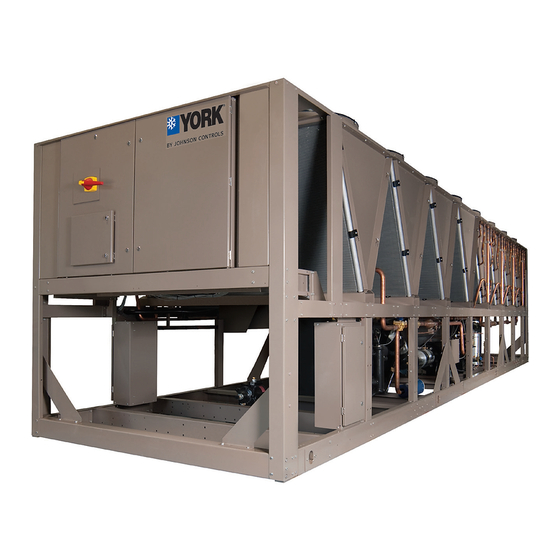
Form 201.28-NM1.1 Issue date: 08/06/2021 Section 2 - Product description YORK YVAA chillers are designed for water or glycol General system description cooling. All units are designed to be located outside on The YVAA Chiller combines the best of modern screw the roof of a building or at ground level. -
Page 16: Figure 2 - Chiller Control System
Form 201.28-NM1.1 SECTION 2 - PRODUCT DESCRIPTION Issue date: 08/06/2021 Inputs Outputs Pressure transducers Relay output board Temperature sensors Switches Solenoids Liquid flow Contactors Control panel High pressure Alarm Chiller control Start/stop Pump board Level Compressor heater Run status Customer supplied Evaporator heater Microprocessor contacts... -
Page 17: Semi-Hermetic York Twin-Screw Compressors
• An economizer (flash) tank is located in each re- Condenser frigerant circuit to increase the system efficiency. The YVAA introduces micro-channel coil to the YORK Electrical screw compressor chiller line. The micro-channel max- imizes condenser heat transfer, resulting in a smaller... -
Page 18: Building Automation System Capabilities
Display data • Leaving Chilled Liquid Temperature • Returning Liquid Temperature • Ambient Temperature • Lead System Figure 3 - View of YORK control center user interface • Compressor Capacity (% of Full Load Amps) JOHNSON CONTROLS... -
Page 19: Accessories And Options
Form 201.28-NM1.1 SECTION 2 - PRODUCT DESCRIPTION Issue date: 08/06/2021 Johnson Controls’ systems or another vendor’s systems condenser coils. This option should be selected if ad- can incorporate these setpoints and data outputs to give ditional airflow resistance may be present due to flow the customer a complete understanding of how the sys- restrictions such as field installed ducts, filters, sound tem is running through a Building Automation System. - Page 20 Form 201.28-NM1.1 SECTION 2 - PRODUCT DESCRIPTION Issue date: 08/06/2021 Louvered/Wire Panels Combination – Louvered pan- Controls Options els, painted the same color as the unit, are mounted on High Ambient Operation – This provides special external condenser coil faces. Heavy gauge, welded control logic coupled with high airflow fans to permit wire-mesh panels, coated to resist corrosion, are mounted high ambient up to 52°C (125°F) operation.
- Page 21 Form 201.28-NM1.1 SECTION 2 - PRODUCT DESCRIPTION Issue date: 08/06/2021 Non-Fused Disconnect Switch – Unit-mounted dis- Thermal Dispersion Flow Switch – Alternative to the paddle-type flow switch and differential pressure connect switch with external lockable handle can be supplied to isolate the unit power voltage for servicing. switch, this electronic flow switch requires 115 VAC 50 Hz or 60 Hz power supply.
- Page 22 FORM 201.28-NM1.1 ISSUE DATE: 12/18/2020 THIS PAGE IS INTENTIONALLY LEFT BLANK JOHNSON CONTROLS...
-
Page 23: Section 3 - Rigging, Handling, And Storage
Form 201.28-NM1.1 Issue date: 08/06/2021 Section 3 - Rigging, handling, and storage LD19197 Rigging and lifting should only be done by a professional rigger in accordance with a written rigging and lifting plan. The most appropriate rigging and lifting method will depend on job specific factors, such as the rigging equipment available and site needs. -
Page 24: Inspection
Form 201.28-NM1.1 SECTION 3 - RIGGING, HANDLING, AND STORAGE Issue date: 08/06/2021 Inspection Remove any transit packing and inspect the unit to ensure that all components have been delivered and that no damage has occurred during transit. If any damage is evident, it should be noted on the carrier’s freight bill and a claim entered in accordance with the instructions given on the advice note. - Page 25 FORM 201.28-NM1.1 SECTION 3 - RIGGING, HANDLING, AND STORAGE ISSUE DATE: 12/18/2020 THIS PAGE IS INTENTIONALLY LEFT BLANK JOHNSON CONTROLS...
-
Page 26: Table 1 - Unit Rigging
Form 201.28-NM1.1 SECTION 3 - RIGGING, HANDLING, AND STORAGE Issue date: 08/06/2021 LD18582 Table 1 - Unit rigging YVAA model Rigging holes Description Units Frame Cond Evap Rigging hole location 1512 2937 4866 Rigging hole location 1533 3482 5435 Rigging hole location 1845 3654... - Page 27 Form 201.28-NM1.1 SECTION 3 - RIGGING, HANDLING, AND STORAGE Issue date: 08/06/2021 LD18582 Table 1 - Unit rigging (cont'd) YVAA model Rigging holes Description Units Frame Cond Evap Rigging hole location 1511 2937 4866 Rigging hole location 1533 3485 5435 Rigging hole location 1845...
- Page 28 Form 201.28-NM1.1 SECTION 3 - RIGGING, HANDLING, AND STORAGE Issue date: 08/06/2021 LD18582 Table 1 - Unit rigging (cont'd) YVAA model Rigging holes Description Units Frame Cond Evap Rigging hole location 1533 3485 5456 6919 Rigging hole location 1533 3789 6088 8218 Rigging hole...
- Page 29 Form 201.28-NM1.1 SECTION 3 - RIGGING, HANDLING, AND STORAGE Issue date: 08/06/2021 LD18582 Table 1 - Unit rigging (cont'd) YVAA model Rigging holes Description Units Frame Cond Evap Rigging hole location 1533 3485 5456 6919 Rigging hole location 1533 3789 6088 8218 Rigging hole...
- Page 30 Form 201.28-NM1.1 SECTION 3 - RIGGING, HANDLING, AND STORAGE Issue date: 08/06/2021 LD18582 Table 1 - Unit rigging (cont'd) YVAA model Rigging holes Description Units Frame Cond Evap Rigging hole location 1845 4092 6443 7763 9941 Rigging hole location 1845 3072 4549 6169...
- Page 31 Form 201.28-NM1.1 SECTION 3 - RIGGING, HANDLING, AND STORAGE Issue date: 08/06/2021 LD18582 Table 1 - Unit rigging (cont'd) YVAA model Rigging holes Description Units Frame Cond Evap Rigging hole location 1845 4092 6443 7763 9941 Rigging hole location 1845 3072 4549 6169...
- Page 32 Form 201.28-NM1.1 SECTION 3 - RIGGING, HANDLING, AND STORAGE Issue date: 08/06/2021 LD18582 Table 1 - Unit rigging (cont'd) YVAA model Rigging holes Description Units Frame Cond Evap Rigging hole location 1845 4602 6039 7358 11059 12135 13835 Rigging hole location 1845 4601...
- Page 33 Form 201.28-NM1.1 SECTION 3 - RIGGING, HANDLING, AND STORAGE Issue date: 08/06/2021 LD18582 Table 1 - Unit rigging (cont'd) YVAA model Rigging holes Description Units Frame Cond Evap Rigging hole location 1845 4602 6039 7358 11059 12135 13835 Rigging hole location 1845 4601...
- Page 34 FORM 201.28-NM1.1 ISSUE DATE: 12/18/2020 THIS PAGE IS INTENTIONALLY LEFT BLANK JOHNSON CONTROLS...
-
Page 35: Section 4 - Installation
Form 201.28-NM1.1 Issue date: 08/06/2021 Section 4 - Installation Location requirements Any ductwork or attenuators fitted to the unit must not For optimum performance and trouble-free service, it have a total static pressure resistance, at full unit air- is essential that the installation site meet the location flow, exceeding the capability of the fans installed in and space requirements for the model being installed. -
Page 36: Figure 5 - Acceptable Minimum Clearances Around And Between Units
Form 201.28-NM1.1 SECTION 4 - INSTALLATION Issue date: 08/06/2021 Recommended minimum clearances Table 2 - Minimum evaporator tube removal clearance Recommended clearances for the YVAA units are: Tube removal Model YVAA clearance dimensions • Side to wall – 6 ft (1.8 m) •... -
Page 37: Vibration Isolators
Form 201.28-NM1.1 SECTION 4 - INSTALLATION Issue date: 08/06/2021 Vibration isolators There should be a straight run of piping of at least Optional sets of vibration isolators can be supplied loose with each unit. 5 pipe diameters on either side. The flow switch should be wired to Terminals 2 and 13 on the 1TB terminal Use the isolator tables shipped with the unit in the in- block. -
Page 38: Evaporator Pressure Drop
Form 201.28-NM1.1 SECTION 4 - INSTALLATION Issue date: 08/06/2021 Drain and air vent connections should be provided at The installer/user must also ensure that all low and high points in the piping to permit drainage the quality of the water in circulation is of the system and to vent any air in the pipes. -
Page 39: Figure 6 - Two Pass Water Pressure Drop, English Units
Form 201.28-NM1.1 SECTION 4 - INSTALLATION Issue date: 08/06/2021 50.0 Water temperature = 50°F 40.0 30.0 20.0 Evaporator Type 10.0 H, K F, G I, J 1000 1200 1400 1600 1800 2000 Flow Rate (GPM) LD20286 Figure 6 - Two pass water pressure drop, English units 50.0 Water Temperature = 50°F 40.0... -
Page 40: Water Treatment
Form 201.28-NM1.1 SECTION 4 - INSTALLATION Issue date: 08/06/2021 Water treatment For air conditioning applications, a minimum of 3 The unit performance provided in the Design Guide gallons/ton is required. with a preferred gallon/ton is based on a fouling factor of 0.018 m2/hr °C/kW ratio to be within the 5 to 8 range. -
Page 41: Thermal Storage
Form 201.28-NM1.1 SECTION 4 - INSTALLATION Issue date: 08/06/2021 or energy costs. Conventional cooling systems pro- duce cooling when it is needed which is commonly during times of peak demand. Thermal storage allows generation of cooling capacity to occur during off- peak periods and store that capacity to meet future cooling requirements. -
Page 42: Table 3 - Evaporator Connections Dimensions
Form 201.28-NM1.1 SECTION 4 - INSTALLATION Issue date: 08/06/2021 Table 3 - Evaporator connections dimensions Flange dimensions (GB only) mm Nominal Frame Cond Evap Grooved size, in. diameter DN150 170.5 241.5 DN150 170.5 241.5 DN150 170.5 241.5 DN150 170.5 241.5 DN150 170.5 241.5... -
Page 43: Refrigerant Relief Valve Piping
Form 201.28-NM1.1 SECTION 4 - INSTALLATION Issue date: 08/06/2021 4 in. / 6 in. / 8 in. flange 10 in. flange LD16185a Figure 13 - Flange for GB vessels Option flanges One of two types of flanges may be fitted depending The size of any piping attached to a relief valve must on the customer or local pressure vessel code require- be of sufficient diameter so as not to cause resistance to... -
Page 44: Power Wiring
Form 201.28-NM1.1 SECTION 4 - INSTALLATION Issue date: 08/06/2021 After power wiring connection, do not Power supply wiring switch on mains power to the unit. Some • Units require only one 3-phase supply, plus earth. internal components are live when the mains are switched on and this must only •... -
Page 45: Volts Free Contacts
Form 201.28-NM1.1 SECTION 4 - INSTALLATION Issue date: 08/06/2021 • Ensure that the sensor tip does not contact the pipe Volts free contacts wall. Do not mount it in a downpipe, in which the Chilled liquid pump starter liquid flows downwards. Terminals 23 and 24 on 1TB close to start the chilled •... -
Page 46: Power Supply Wiring
Form 201.28-NM1.1 SECTION 4 - INSTALLATION Issue date: 08/06/2021 Power supply wiring Single point wiring UNIT MOUNTED ELECTRONICS STANDARD UNIT CONTROLS CONTROL INVERTER INVERTER TRANSFORMER EVAPORATOR HEATER LINE CONTACTORS REACTOR TERMINAL BLOCK (CIRCUIT BREAKER - OPT) WATER BOX (NON-FUSED DISCONNECT HEATER SWITCH - OPT) SEE NOTE 1... -
Page 47: Figure 16 - Dual Point Power Wiring
Form 201.28-NM1.1 SECTION 4 - INSTALLATION Issue date: 08/06/2021 Dual point wiring UNIT MOUNTED ELECTRONICS STANDARD UNIT CONTROLS CONTROL EVAPORATOR AND COMPRESSOR TRANSFORMER HEATERS POWER POWER ASSEMBLY ASSEMBLY VSD COOLING PUMP SYSTEM 2 AND FAN SYSTEM 1 LINE LINE CONTACTORS CONTACTORS REACTOR REACTOR... -
Page 48: Customer Control Wiring
CONTACTS CHILLER LEGEND TERMINAL BLOCK FOR CUSTOMER CONNECTIONS TERMINAL BLOCK FOR YORK CONNECTIONS WIRING AND COMPONENTS BY YORK OPTIONAL EQUIPMENT WIRING AND/OR COMPONENTS BY OTHERS In subfreezing regions, failure to connect EVAP. PUMP START SIGNAL from terminal 23 and ter- minal 24 to chilled water pump starter will void warranty, except when the water in the evaporator is fully dried or appropriate concentration of glycol is reached in the water system. -
Page 49: Thermal Dispersion Flow Switch Connections
Form 201.28-NM1.1 SECTION 4 - INSTALLATION Issue date: 08/06/2021 Thermal dispersion flow switch connections TO FLOW SWITCH INPUT TERMINALS 2 AND 13 RED/YEL NOT USED TO 115 V AC 1.88 RED/BLK SUPPLY RED/WHT 1.13 PIPE COUPLING NB: INSERT PROBE INTO COMPRESSION CLAMP SO THE PROBE TIP EXTENDS WATER PIPE WORK INTO THE PIPE ID BETWEEN 1 IN. -
Page 50: Figure 19 - Reserved Customer Wiring Entry
Form 201.28-NM1.1 SECTION 4 - INSTALLATION Issue date: 08/06/2021 RESERVED FOR CUSTOMER WIRING ENTRY LD28284 Figure 19 - Reserved customer wiring entry Failure to connect the power connection For YVAA chillers, if the water box heater option is to the water box heater wiring box, or to available, the customer has to connect a 115 V/60 Hz or meet IP65, will void warranty. - Page 51 Form 201.28-NM1.1 SECTION 4 - INSTALLATION Issue date: 08/06/2021 Connect the 115 V/60 Hz or 220 V/50 Hz power sup- Evaporator heaters used in the unit may ply to the top terminals of the 2-pole-breaker, as shown malfunction without alarm. Once the in Figure 20.
-
Page 52: Table 4 - Electrical Lug Data
Form 201.28-NM1.1 SECTION 4 - INSTALLATION Issue date: 08/06/2021 Table 4 - Electrical lug data Standard and ultra quiet condenser fans Field wiring lugs Non-fused disconnect Terminal block Circuit breaker switch YVAA MODEL Wires Input Input Wires per Wires per Lug wire Lug wire range Lug wire range... - Page 53 Form 201.28-NM1.1 SECTION 4 - INSTALLATION Issue date: 08/06/2021 Table 4 - Electrical lug data (cont'd) High airflow/high static condenser fans Field wiring lugs Non-fused disconnect Terminal block Circuit breaker switch YVAA model Wires Input Input Wires per Wires per Lug wire range Lug wire range Lug wire range...
- Page 54 Form 201.28-NM1.1 SECTION 4 - INSTALLATION Issue date: 08/06/2021 Table 4 - Electrical lug data (cont'd) STANDARD & ULTRA QUIET CONDENSER FANS Field wiring lugs Non-fused disconnect Terminal block Circuit breaker switch YVAA model Wires Wires Wires Input Input Lug wire Lug wire range Lug wire range Frame...
- Page 55 Form 201.28-NM1.1 SECTION 4 - INSTALLATION Issue date: 08/06/2021 Table 4 - Electrical lug data (cont'd) High airflow/high static condenser fans Field wiring lugs Non-fused disconnect Terminal block Circuit breaker switch YVAA model Wires Input Input Wires per Wires per Lug wire range Lug wire range Lug wire range...
- Page 56 Form 201.28-NM1.1 SECTION 4 - INSTALLATION Issue date: 08/06/2021 Table 4 - Electrical lug data (cont'd) Standard and ultra quiet condenser fans Field wiring lugs Non-fused disconnect Terminal block Circuit breaker switch YVAA model Wires Wires Input Input Lug wire Wires per Lug wire range Lug wire range...
- Page 57 Form 201.28-NM1.1 SECTION 4 - INSTALLATION Issue date: 08/06/2021 Table 4 - Electrical lug data (cont'd) High airflow/high static condenser fans Field wiring lugs Non-fused disconnect Terminal block Circuit breaker switch YVAA model Wires Input Input Wires per Wires per Lug wire range Lug wire range Lug wire range...
- Page 58 Form 201.28-NM1.1 SECTION 4 - INSTALLATION Issue date: 08/06/2021 Table 4 - Electrical lug data (cont'd) Standard and ultra quiet condenser fans Field wiring lugs Non-fused disconnect Terminal block Circuit breaker switch YVAA model Wires Wires Wires Input Input Lug wire range Lug wire range Lug wire range Frame...
- Page 59 Form 201.28-NM1.1 SECTION 4 - INSTALLATION Issue date: 08/06/2021 Table 4 - Electrical lug data (cont'd) High airflow/High static condenser fans Field wiring lugs Non-fused disconnect Terminal block Circuit breaker switch YVAA model Wires Input Input Wires per Wires per Lug wire range Lug wire range Lug wire range...
- Page 60 Form 201.28-NM1.1 SECTION 4 - INSTALLATION Issue date: 08/06/2021 Table 4 - Electrical lug data (cont'd) Standard and ultra quiet condenser fans Field wiring lugs Non-fused disconnect Terminal block Circuit breaker switch YVAA model Wires Wires Input Input Wires per Lug wire range Lug wire range Lug wire range...
- Page 61 Form 201.28-NM1.1 SECTION 4 - INSTALLATION Issue date: 08/06/2021 Table 4 - Electrical lug data (cont'd) High airflow/high static condenser fans Field wiring lugs Non-fused disconnect Terminal block Circuit breaker switch YVAA model Wires Wires Wires Input Input Lug wire range Lug wire range Lug wire range Frame Cond...
- Page 62 FORM 201.28-NM1.1 ISSUE DATE: 12/18/2020 THIS PAGE IS INTENTIONALLY LEFT BLANK JOHNSON CONTROLS...
-
Page 63: Section 5 - Technical Data
Form 201.28-NM1.1 Issue date: 08/06/2021 Section 5 - Technical data The data shown within the tables of this chapter, are Contact your nearest Johnson Controls Sales applicable to selected typical configurations. Other Office for the chiller configuration that best matches configurations are available through our configuration your specific needs. -
Page 64: Table 5 - Physical Data - Microchannel Coil
Form 201.28-NM1.1 SECTION 5 - TECHNICAL DATA Issue date: 08/06/2021 Table 5 - Physical data - Microchannel coil Unit frame Condenser code Evaporator code General unit data Number of Independent Refrigerant Circuits Refrigerant Charge, 175/175 190/190 225/225 175/155 190/170 220/195 205/205 175/175 240/240... - Page 65 Form 201.28-NM1.1 SECTION 5 - TECHNICAL DATA Issue date: 08/06/2021 Table 5 - Physical data - Microchannel coil (cont'd) Unit frame Condenser code Evaporator code General unit data Number of Independent Refrigerant Circuits Refrigerant Charge, 210/190 250/225 250/250 210/210 250/250 265/265 265/265 270/270...
- Page 66 Form 201.28-NM1.1 SECTION 5 - TECHNICAL DATA Issue date: 08/06/2021 Table 5 - Physical data - Microchannel coil (cont'd) Unit frame Condenser code Evaporator code General unit data Number of Independent Refrigerant Circuits Refrigerant Charge, R-134a, or 295/250 315/275 315/295 295/295 290/290 310/310...
- Page 67 Form 201.28-NM1.1 SECTION 5 - TECHNICAL DATA Issue date: 08/06/2021 Table 5 - Physical data - Microchannel coil (cont'd) Unit frame Condenser code Evaporator code General unit data Number of Independent Refrigerant Circuits Refrigerant Charge, R-134a, or 470/310 475/360 460/345 480/365 475/385 370/370...
-
Page 68: Table 6 - Physical Data - Round Tube Coil
Form 201.28-NM1.1 SECTION 5 - TECHNICAL DATA Issue date: 08/06/2021 Table 6 - Physical data - Round tube coil Unit frame Condenser code Evaporator code General unit data Number of Independent Refrigerant Circuits Refrigerant Charge, R-134a, Ckt.- 210/210 229/191 241/241 229/229 273/235 273/273... - Page 69 Form 201.28-NM1.1 SECTION 5 - TECHNICAL DATA Issue date: 08/06/2021 Table 6 - Physical data - Round tube coil (cont'd) Unit frame Condenser code Evaporator code General unit data Number of Independent Refrigerant Circuits Refrigerant Charge, R-134a, Ckt.-1/ 367/367 371/371 391/391 537/308 568/417...
-
Page 70: Table 7 - Optional One-Pass Evaporator
Form 201.28-NM1.1 SECTION 5 - TECHNICAL DATA Issue date: 08/06/2021 Table 7 - Optional one-pass evaporator All dimensions - in. (mm) YVAA Minimum chilled Maximum chilled Water volume gal E-nozzle size water flow rate water flow rate GPM (L/S) GPM (L/S) 20.8 34.5 1970... - Page 71 Form 201.28-NM1.1 SECTION 5 - TECHNICAL DATA Issue date: 08/06/2021 Table 7 - Optional one-pass evaporator (cont'd) All dimensions - in. (mm) YVAA Minimum chilled Maximum chilled Water volume gal E-nozzle size water flow rate water flow rate GPM (L/S) GPM (L/S) 20.8 73.2...
- Page 72 Form 201.28-NM1.1 SECTION 5 - TECHNICAL DATA Issue date: 08/06/2021 Table 7 - Optional one-pass evaporator (cont'd) All dimensions - in. (mm) YVAA Wwater volume Minimum chilled Maximum chilled E-nozzle size water flow rate water flow rate GPM (L/S) GPM (L/S) 166.9 2190 (533)
- Page 73 Form 201.28-NM1.1 SECTION 5 - TECHNICAL DATA Issue date: 08/06/2021 Table 7 - Optional one-pass evaporator (cont'd) All dimensions - in. (mm) YVAA Wwater volume Minimum chilled Maximum chilled E-nozzle size water flow rate water flow rate GPM (L/S) GPM (L/S) 23.3 252.5 83.5...
-
Page 74: Table 8 - Standard Two-Pass, Rear Inlet/Outlet Evaporator
Form 201.28-NM1.1 SECTION 5 - TECHNICAL DATA Issue date: 08/06/2021 Table 8 - Standard two-pass, rear inlet/outlet evaporator All dimensions - in. (mm) YVAA Minimum Maximum Water E-nozzle chilled water chilled water volume gal size flow rate flow rate GPM (L/S) GPM (L/S) 15.1 11.4... - Page 75 Form 201.28-NM1.1 SECTION 5 - TECHNICAL DATA Issue date: 08/06/2021 Table 8 - Standard two-pass, rear inlet/outlet evaporator (cont'd) All dimensions - in. (mm) YVAA Minimum Maximum Water E-nozzle chilled water chilled water volume gal size flow rate flow rate GPM (L/S) GPM (L/S) 15.1...
- Page 76 Form 201.28-NM1.1 SECTION 5 - TECHNICAL DATA Issue date: 08/06/2021 Table 8 - Standard two-pass, rear inlet/outlet evaporator (cont'd) All dimensions - in. (mm) YVAA Maximum Minimum Water chilled E-nozzle chilled water volume gal water flow size flow rate rate GPM GPM (L/S) (L/S) 15.3...
- Page 77 Form 201.28-NM1.1 SECTION 5 - TECHNICAL DATA Issue date: 08/06/2021 Table 8 - Standard two-pass, rear inlet/outlet evaporator (cont'd) All dimensions - in. (mm) YVAA Maximum Minimum Water chilled E-nozzle chilled water volume gal water flow size flow rate rate GPM GPM (L/S) (L/S) 16.3...
-
Page 78: Table 9 - Optional Three-Pass Rear Inlet/Front Outlet Evaporator
Form 201.28-NM1.1 SECTION 5 - TECHNICAL DATA Issue date: 08/06/2021 Table 9 - Optional three-pass rear inlet/front outlet evaporator All dimensions - in. (mm) YVAA Minimum Water Maximum chilled E- nozzle chilled water volume gal water flow rate size flow rate GPM (L/S) GPM (L/S) 15.1... - Page 79 Form 201.28-NM1.1 SECTION 5 - TECHNICAL DATA Issue date: 08/06/2021 Table 9 - Optional three-pass rear inlet/front outlet evaporator (cont'd) All dimensions - in. (mm) YVAA Minimum Water Maximum chilled E- nozzle chilled water volume gal water flow rate size flow rate GPM (L/S) GPM (L/S)
- Page 80 Form 201.28-NM1.1 SECTION 5 - TECHNICAL DATA Issue date: 08/06/2021 Table 9 - Optional three-pass rear inlet/front outlet evaporator (cont'd) All dimensions - in. (mm) YVAA Minimum Water Maximum chilled chilled water E-nozzle size volume gal water flow rate flow rate GPM (L/S) GPM (L/S) 15.3...
- Page 81 Form 201.28-NM1.1 SECTION 5 - TECHNICAL DATA Issue date: 08/06/2021 Table 9 - Optional three-pass rear inlet/front outlet evaporator (cont'd) All dimensions - in. (mm) YVAA Minimum Water Maximum chilled chilled water E-nozzle size volume gal water flow rate flow rate GPM (L/S) GPM (L/S) 16.3...
-
Page 82: Figure 21 - Yvaa Dimensions
Form 201.28-NM1.1 SECTION 5 - TECHNICAL DATA Issue date: 08/06/2021 The following data is applicable to select configura- Contact your nearest Johnson Controls Sales tions. Other configurations are available through our Office for the chiller configuration that best matches configuration/selection software. your specific needs. - Page 83 FORM 201.28-NM1.1 SECTION 5 - TECHNICAL DATA ISSUE DATE: 12/18/2020 THIS PAGE IS INTENTIONALLY LEFT BLANK JOHNSON CONTROLS...
-
Page 84: Table 10 - Isolator Selection And Mounting Locations
Form 201.28-NM1.1 SECTION 5 - TECHNICAL DATA Issue date: 08/06/2021 LD18587 Table 10 - Isolator selection and mounting locations YVAA configuration Description Frame Cond Evap Isolator X-Dimension (263) (1852) (3662) (4900) Isolator Y-Dimension 1 (34) Isolator X-Dimension (263) (1943) (3000) (3985) (5589) Isolator Y-Dimension... - Page 85 Form 201.28-NM1.1 SECTION 5 - TECHNICAL DATA Issue date: 08/06/2021 LD18587 Table 10 - Isolator selection and mounting locations (cont'd) YVAA CONFIGURATION Descriptio Frame Cond Evap Isolator X-Dimension (263) (1852) (3662) (4900) Isolator Y-Dimension 87 (2206) Isolator X-Dimension (263) (1943) (3000) (3985) (5589)
- Page 86 Form 201.28-NM1.1 SECTION 5 - TECHNICAL DATA Issue date: 08/06/2021 Table 10 - Isolator selection and mounting locations (cont'd) YVAA configuration Description Frame Cond Evap Isolator X-Dimension (263) (1943) (2999) (3984) (5298) (7823) Isolator Y-Dimension 1 (34) Isolator X-Dimension (263) (2057) (3779) (4756)
- Page 87 Form 201.28-NM1.1 SECTION 5 - TECHNICAL DATA Issue date: 08/06/2021 Table 10 - Isolator selection and mounting locations (cont'd) YVAA CONFIGURATION Descriptio Frame Cond Evap Isolator X-Dimension (263) (1943) (2999) (3984) (5298) (7823) Isolator Y-Dimension 87 (2206) Isolator X-Dimension (263) (2057) (3779) (4756)
- Page 88 Form 201.28-NM1.1 SECTION 5 - TECHNICAL DATA Issue date: 08/06/2021 Table 10 - Isolator selection and mounting locations (cont'd) YVAA configuration Description Frame Cond Evap Isolator X-Dimension (263) (2057) (3680) (5219) (7218) (10842) Isolator Y-Dimension 1 (34) Isolator X-Dimension (263) (2057) (3680) (5219)
- Page 89 Form 201.28-NM1.1 SECTION 5 - TECHNICAL DATA Issue date: 08/06/2021 Table 10 - Isolator selection and mounting locations (cont'd) YVAA CONFIGURATION Descriptio Frame Cond Evap Isolator X-Dimension (263) (2057) (3680) (5219) (7218) (10842) Isolator Y-Dimension 87 (2206) Isolator X-Dimension (263) (2057) (3680) (5219)
-
Page 90: Elastomeric Isolator Installation
Form 201.28-NM1.1 SECTION 5 - TECHNICAL DATA Issue date: 08/06/2021 Elastomeric isolator installation Top bolt Top washer SECTION D-D Section D-D LD13762C Read the following instructions before beginning 3. Bolt or anchor all isolators to supporting structure installation. utilizing base thru holes (B). 1. -
Page 91: Elastomeric Isolator Specifications
Form 201.28-NM1.1 SECTION 5 - TECHNICAL DATA Issue date: 08/06/2021 Elastomeric isolator specifications MOLDED DURULENE MOLDED DURULENE Ø = AD Thru Typ 2 Places R = 0.280 Slot Typ 2 Places LD17304 Dimension data (in.) Model P/N Type A 029-25335-001 5.50 3.38 2.88... -
Page 92: One Inch Deflection Isolator Installation
Form 201.28-NM1.1 SECTION 5 - TECHNICAL DATA Issue date: 08/06/2021 One inch deflection isolator installation EQUIPMENT POSITIONING BASE UPPER PIN (H) HOUSING 0.25” min - 0.5” max LOWER HOUSING NON-SKID ELASTOMERIC 4. Place equipment on top of isolators making sure Read the following instructions before beginning that mounting holes of the equipment line up with installation. -
Page 93: One Inch Deflection Spring Isolator Specifications
Form 201.28-NM1.1 SECTION 5 - TECHNICAL DATA Issue date: 08/06/2021 One inch deflection spring isolator specifications 5/8" H" C" T" B" L" D" W" Dimension data (in.) Mount type Type A 7 3/4 6 1/2 4-3/4 5 5/8 Type B 10 1/2 9 1/4 7 3/4... -
Page 94: Two Inch Deflection Isolator Installation And Adjustment
Form 201.28-NM1.1 SECTION 5 - TECHNICAL DATA Issue date: 08/06/2021 Two inch deflection, isolator installation and adjustment ("G") ("E") ("A") ("E") ("A") GROMMET 1/4 - 3/8 GAP EQUIPMENT ("F") WASHER ("E") ("F") ("C") ("C") ("B") Read the following instructions before beginning 6. -
Page 95: Two Inch Deflection, Restrained Spring Isolator Specifications
Form 201.28-NM1.1 SECTION 5 - TECHNICAL DATA Issue date: 08/06/2021 Two inch deflection, restrained spring isolator specifications 1-1/8" 5" 5/8" 2-3/4" 2-3/4" 12" 3/8" GAP 5/8-11UNC Ø3/4" TYP. (4) TYP.(4) 3/4" 7/8" 1/2" LIMIT STOP & 8-3/8" OPER. HEIGHT 12-1/4" 14"... - Page 96 FORM 201.28-NM1.1 ISSUE DATE: 12/18/2020 THIS PAGE IS INTENTIONALLY LEFT BLANK JOHNSON CONTROLS...
-
Page 97: Section 6 - Commissioning
Compressor oil repaired. To add oil to a circuit - connect a YORK hand oil pump Do not evacuate or liquid charge with static water (Part No. 470-10654-000) to the 1/4 in. (6.35 mm) oil in the evaporator. -
Page 98: Figure 22 - Led Indicator Buttons
Form 201.28-NM1.1 SECTION 6 - COMMISSIONING Issue date: 08/06/2021 High oil concentration in the system may cause Flow rates and pressure drops must be within the limits nuisance trips resulting from incorrect readings on the given in SECTION 5 - TECHNICAL DATA. Operation level sensor and temperature sensors. -
Page 99: Figure 23 - Flow Switch Set
Form 201.28-NM1.1 SECTION 6 - COMMISSIONING Issue date: 08/06/2021 Setting the thermal dispersion flow switch Temperature sensors To set up the flow switch, perform a high-flow adjust- Ensure that leaving liquid temperature ment, which is a quick reaction with falling low. sensor is coated with heat conductive compound (Part No. -
Page 100: First Time Startup
Form 201.28-NM1.1 SECTION 6 - COMMISSIONING Issue date: 08/06/2021 First time startup Condenser and fan rotation During the commissioning period there Once a compressor is running, discharge pressure should be sufficient heat load to run the rises as refrigerant is pumped into the air-cooled con- unit under stable full load operation to denser coils. -
Page 101: Table 11 - Freeze Damage Protection Requirements
Form 201.28-NM1.1 SECTION 6 - COMMISSIONING Issue date: 08/06/2021 A. An appropriate freeze protection fluid selected for the lowest possible ambient temperature must be used in the chilled fluid circuit..-or- B. The fluid in the evaporator must be drained by completing the following steps: •... - Page 102 FORM 201.28-NM1.1 ISSUE DATE: 12/18/2020 THIS PAGE IS INTENTIONALLY LEFT BLANK JOHNSON CONTROLS...
-
Page 103: Section 7 - Operation
Form 201.28-NM1.1 Issue date: 08/06/2021 Section 7 - Operation Operating controls The keypad also contains keys in the center section for data entry in the various program modes. These keys Display are as follows: • 0-9 Keys NUMERIC KEYPAD • PERIOD/DECIMAL •... - Page 104 Form 201.28-NM1.1 SECTION 7 - OPERATION Issue date: 08/06/2021 The ◄ (LEFT ARROW) key allows programming the XXXXXXXXXXX OUT OF RANGE TRY AGAIN! default value when programming numeric values. For XXXXXXXXXXXXXXXXXXXXXXXXXXXXXXXXXXXX changing numeric values, the ► (RIGHT ARROW) key has no function. Display The ◄...
-
Page 105: Basic Operating Sequence
Form 201.28-NM1.1 SECTION 7 - OPERATION Issue date: 08/06/2021 Changing the switch point of the thermal Chiller controller cannot detect the failure dispersion flow switch of all the heaters used in compressor, oil separator, evaporator shell and evaporator To change the factory-set LED 7, complete the follow- water box, etc. -
Page 106: Unit Warning
Form 201.28-NM1.1 SECTION 7 - OPERATION Issue date: 08/06/2021 sors to start and begin operation of the compressors. The 03478 program resides in flash memory instead The compressors speed will be ramped to the minimum of EPROM. Program updates are accomplished by start frequency and increase speed as needed in an ef- loading the new program from an SD card inserted into fort to regulate the leaving chilled liquid temperature to... - Page 107 Form 201.28-NM1.1 SECTION 7 - OPERATION Issue date: 08/06/2021 Power supply test points TP1 GND (Measure TP2, TP3, TP4 and TP5 in reference to this Test Point). TP2 +3.3 V [3.2 VDC to 3.4 VDC] provides power to the processors. TP3 +5 V [4.8 VDC to 5.2 VDC] power communica- tion ports 2,3 and 4 and analog sensors.
-
Page 108: Figure 27 - New 331-03478-Xxx Microboard
Form 201.28-NM1.1 SECTION 7 - OPERATION Issue date: 08/06/2021 LD19331 Number Description Number Description Number Description Number Description Port 1 Port 2 Native BAS TP3 +5 V Power LED RX2, TX2 (BACnet and PORT 2 RS-232 TP2 +3.3 V Status LED TP1 GND Printer or Modbus VSD RX... -
Page 109: Building Automation System (Bas) Communications
Form 201.28-NM1.1 SECTION 7 - OPERATION Issue date: 08/06/2021 Building automation system (BAS) communications There are three different ways the chiller communi- 6. P1 Parity: set to NONE (Default Setting). cates to the BAS. 7. P1 Stop Bits: set to 1 (Default Setting). •... -
Page 110: E-Link Or Sc-Eq Interface
Form 201.28-NM1.1 SECTION 7 - OPERATION Issue date: 08/06/2021 MODBUS (RTU) setup port 2 J13-5 Remote Stop Start must be closed for BAS The YVAA 03478 microboard supports Modbus RS232 remote commands to take effect. If this input is open or RS485 communications for Port 2 communications. -
Page 111: Table 12 - Values Required For Bas Communication
Form 201.28-NM1.1 SECTION 7 - OPERATION Issue date: 08/06/2021 The following table shows set-up requirements for each communication protocol. Table 12 - Values required for BAS communication Protocol Setting description BACnet MS/TP Modbus RTU YorkTalk2 DE modifier address 0 to 41943 DE modifier offset 0 to 99 P1 protocol... -
Page 112: Table 13 - Real Time Error Numbers For Bas, Sc-Eq Or E-Link Communications Card
DE modifier address is set to -1. GET PACKET FAILED The most current data map information GET TYPE FAILED is listed on the Johnson Controls/YORK INVALID UNIT CONVERSION Chiller Equipment Integration website. A INVALID HARDWARE SELECTION... -
Page 113: Sc-Eq Or E-Link Bas Communications Card
Form 201.28-NM1.1 SECTION 7 - OPERATION Issue date: 08/06/2021 SC-EQ or E-Link BAS communications card Transmitted data After receiving a valid transmission from the SC-EQ or Received data (Control data) E-Link, the chiller will transmit either operational data The chiller receives eight data values from the SC-EQ or or history buffer data depending on the History Buffer E-Link. -
Page 114: Table 14 - Yvaa Native Communications Data Map
Form 201.28-NM1.1 SECTION 7 - OPERATION Issue date: 08/06/2021 Table 14 - YVAA native communications data map JOHNSON CONTROLS... - Page 115 Form 201.28-NM1.1 SECTION 7 - OPERATION Issue date: 08/06/2021 Table 14 - YVAA native communications data map (Cont'd) JOHNSON CONTROLS...
- Page 116 Form 201.28-NM1.1 SECTION 7 - OPERATION Issue date: 08/06/2021 Table 14 - YVAA native communications data map (cont'd) JOHNSON CONTROLS...
-
Page 117: Table 15 - Yvaa Operational And Fault/Inhibit Codes
Form 201.28-NM1.1 SECTION 7 - OPERATION Issue date: 08/06/2021 Table 15 - YVAA operational and fault/inhibit codes NOTES Units have Native BACnet MS/TP, Modbus RTU, and N2 communications. No external Gateway is required for these interfaces unless the customer is using Connected Services. BACnet Object Types: 0 = Analog In, 1 = Analog Out, 2 = Analog Value, 3 = Binary In, 4 = Binary Out, 8 = Device, 15 = Alarm Notification (0-127 are reserved ASHRAE Objects) WC = Inches of water Column, CFM = Cubic Feet per Minute, FPM = Feet Per Minute, PSI = Pounds per Square Inch, Pa = Pascals, kPa = kiloPascals, PPM = Parts Per Million, kJ/kg = kiloJoules per kilogram Values that are not applicable due to unit configuration and options will be sent as zero (0). -
Page 118: Table 16 - Yvaa E-Link Communications Data Map
Form 201.28-NM1.1 SECTION 7 - OPERATION Issue date: 08/06/2021 Table 16 - YVAA E-Link communications data map JOHNSON CONTROLS... - Page 119 Form 201.28-NM1.1 SECTION 7 - OPERATION Issue date: 08/06/2021 Table 16 - YVAA E-Link communications data map (cont'd) JOHNSON CONTROLS...
- Page 120 Form 201.28-NM1.1 SECTION 7 - OPERATION Issue date: 08/06/2021 Table 16 - YVAA E-Link communications data map (cont'd) JOHNSON CONTROLS...
- Page 121 Form 201.28-NM1.1 SECTION 7 - OPERATION Issue date: 08/06/2021 Table 16 - YVAA E-Link communications data map (cont'd) JOHNSON CONTROLS...
- Page 122 Form 201.28-NM1.1 SECTION 7 - OPERATION Issue date: 08/06/2021 Table 16 - YVAA E-Link communications data map (cont'd) JOHNSON CONTROLS...
-
Page 123: Program Update
Form 201.28-NM1.1 SECTION 7 - OPERATION Issue date: 08/06/2021 9. After the update is completed and the controller J2 VSD#1 and J1 VSD#2 connections headers for reboots, the keypad and display will return to full- RS-485 communications to the Variable Speed Drives. functionality. - Page 124 Form 201.28-NM1.1 SECTION 7 - OPERATION Issue date: 08/06/2021 Follow all JCI Safety Directives when in- Invalid number of compressors warning serting or removing the SD card since the The INVALID NUMBER OF COMPRESSORS card is located inside the control cabinet. SELECTED warning will occur after the VSD has been initialized, if no jumpers are installed or if more than 1 jumper is installed, ”Number of Compressors...
-
Page 125: Unit Safeties
Form 201.28-NM1.1 SECTION 7 - OPERATION Issue date: 08/06/2021 Unit safeties Low ambient temp fault If the ambient temperature falls below the program- Unit safety operation mable Low Ambient Temp Cutout the chiller will Unit faults are safeties that cause all running compres- shut down with a controlled ramped shutdown. -
Page 126: System Safeties, Faults
Form 201.28-NM1.1 SECTION 7 - OPERATION Issue date: 08/06/2021 and have been successfully initialized, the Chiller and these faults will be recorded as such under the Control Board will not request them again. If the com- HISTORY information stored at the instant of the pri- ms connection fails to occur and a reply from the VSD mary fault. - Page 127 Form 201.28-NM1.1 SECTION 7 - OPERATION Issue date: 08/06/2021 The HPCO is wired in series with the VSD Run This safety fault is released when the Suction Pressure Signal and will only be checked by the Chiller >= Suction Pressure Override Threshold. This fault Control Board when the system is running.
-
Page 128: Table 18 - Low Differential Oil Pressure Cutout
Form 201.28-NM1.1 SECTION 7 - OPERATION Issue date: 08/06/2021 Low differential oil pressure cutout fault High discharge temperature cutout fault The Low Differential Oil Pressure Cutout protects the The High Discharge Temperature Cutout protects the compressor from low oil flow and insufficient lubrica- motor and compressor from overheating. -
Page 129: Table 19 - Discharge Pressure Load Limiting/Unloading
Form 201.28-NM1.1 SECTION 7 - OPERATION Issue date: 08/06/2021 The discharge pressure unload point is fixed at 255 Table 19 - Suction pressure load limiting/unloading psig. R-134A Suction pressure Unloading Table 18 - Discharge pressure load limiting/unloading Suction Pressure is between "Cutout +2.60 psig"... -
Page 130: Table 21 - Start Inhibit Sensor Thresholds
Form 201.28-NM1.1 SECTION 7 - OPERATION Issue date: 08/06/2021 The X indicates the specific system. System control voltage cutout fault YYYYYYYY will either indicate the system The System Control Voltage Cutout alerts the operator is in a “FAULT” condition and will restart the 115 VAC Control voltage to one of the systems is when the fault clears, or “LOCKOUT”... -
Page 131: Section 8 - Micropanel
• System safeties General status messages When power is first applied to the control panel, the UNIT STATUS following message displaying YORK International MANUAL OVERRIDE Corporation, the EPROM version, date, and time will be displayed for 2 seconds, followed by the appropriate... - Page 132 Form 201.28-NM1.1 SECTION 8 - MICROPANEL Issue date: 08/06/2021 message will be displayed on the lag system until the UNIT STATUS loading sequence is ready for the lag system to start. UNIT SWITCH OFF SHUTDOWN This message indicates the UNIT SWITCH is in the SYS X COOLING DEMAND SHUTDOWN OFF position and not allowing the unit to run.
- Page 133 Form 201.28-NM1.1 SECTION 8 - MICROPANEL Issue date: 08/06/2021 The VSD Internal Ambient Temp Limiting message SYS X PULLDOWN MOTOR CURRENT LIMITING indicates the VSD internal ambient temp is high and load limit or unloading is in effect. The pulldown motor current limiting message indicates the pulldown motor current load limit or pulldown SYS X SOUND LIMITING motor current unloading is in effect based on the...
-
Page 134: Unit Data Key
Form 201.28-NM1.1 SECTION 8 - MICROPANEL Issue date: 08/06/2021 Unit data key Unit data LD10605 General The UNIT DATA key provides the user with displays UNIT TEMP ERROR = XXX.X °F of unit temperatures, and unit related data. Displays RATE = XXX.X °F/M can be selected by repeatedly pressing the UNIT DATA key or the▲... - Page 135 Form 201.28-NM1.1 SECTION 8 - MICROPANEL Issue date: 08/06/2021 The types of remote control are listed as follows: The next key press displays the sound limit values as set under the PROGRAM key by the Local, ISN, and the • NONE - No remote control is actively controlling Remote Sound Limit Inputs.
-
Page 136: System Data Keys 1 Through 4
Form 201.28-NM1.1 SECTION 8 - MICROPANEL Issue date: 08/06/2021 System data keys 1 through 4 System 1 data key System 2 data key System 3 data key System 4 data key LD10605 General The data keys provide the user with many displays of The next key press displays system oil and eductor temperatures. - Page 137 Form 201.28-NM1.1 SECTION 8 - MICROPANEL Issue date: 08/06/2021 If any motor temp sensor is being ignored, The next key press will indicate the state of the (selectable under Unit Set-up Mode), optional VI solenoids where XXX indicates ON or that sensor’s value will be displayed as OFF.
-
Page 138: Table 22 - Sensor Min/Max Outputs
Form 201.28-NM1.1 SECTION 8 - MICROPANEL Issue date: 08/06/2021 Sensor displays If values exceed the limits in the table, a < (less than) Table 21 on page 138 lists all the sensors attached to the control board associated with system data keys. or >... -
Page 139: Vsd Data Key
Form 201.28-NM1.1 SECTION 8 - MICROPANEL Issue date: 08/06/2021 VSD data key data key LD10605 General The next key press displays DC Bus voltage. The VSD DATA key provides the user with displays of VSD temperatures, voltages, currents, and other oper- DC BUS VOLTAGE = XXX VDC ating data. -
Page 140: Table 23 - Compressor Motor Overload Settings
Form 201.28-NM1.1 SECTION 8 - MICROPANEL Issue date: 08/06/2021 Table 22 - Compressor motor overload settings 380 V - 60 Hz 400 V - 50 Hz 460 V- 60 Hz (see note 1) Model Sys # 1 Sys # 2 Sys # 1 Sys # 2 Sys # 1... -
Page 141: Operating Hours/Start Counter Key
Form 201.28-NM1.1 SECTION 8 - MICROPANEL Issue date: 08/06/2021 Operating hours/Start counter key Operating hours/ Start counter key LD10605 Compressor operating hours and compressor starts are A single display is available under this key and is dis- displayed with a single key press. The maximum value played as follows. -
Page 142: History Key
Form 201.28-NM1.1 SECTION 8 - MICROPANEL Issue date: 08/06/2021 History key History key LD10605 History key operation The HISTORY key provides the user access to many XX is the normal shutdown number. The display pro- unit and system operating parameters captured at the vides date and time of the shutdown and the reason for instant a unit or system safety (fault) shutdown occurs. - Page 143 Form 201.28-NM1.1 SECTION 8 - MICROPANEL Issue date: 08/06/2021 XX is the FAULT HISTORY shutdown number. The Unit fault type display will provide the date, time, and a description of UNIT FAULT the specific type of fault that occurred (YYY….). LOW AMBIENT TEMP The operator can view any of the stored 10 fault history This message indicates the type of unit fault.
- Page 144 Form 201.28-NM1.1 SECTION 8 - MICROPANEL Issue date: 08/06/2021 Load/unload timers VSD data UNIT LOAD TIMER = XXX SEC VSD actual and command frequency UNLOAD TIMER = XXX SEC VSD FREQUENCY ACTUAL = XXX.X HZ COMMAND = XXX.X HZ This message indicates remaining time on the load and unload timers at the time of the fault.
- Page 145 Form 201.28-NM1.1 SECTION 8 - MICROPANEL Issue date: 08/06/2021 Precharge signal status and VSD cooling Compressor speed and heater status status SYS 1 COMPRESSOR SPEED = XXX.X % HEATER = XXX.X °F PRECHARGE SIGNAL = XXX This message indicates the compressor speed in % and the heater status at the time of the fault.
- Page 146 Form 201.28-NM1.1 SECTION 8 - MICROPANEL Issue date: 08/06/2021 Compressor #1 run time Maximum remote temperature setpoint SYS 1 RUN TIME SETPOINTS XX DAYS XX HOURS XX MINUTES XX SECONDS MAXIMUM REMOTE TEMP RESET = XXX.X °F This message displays the system run time since the This message displays the maximum remote reset pro- last start in days, hours, minutes, and seconds at the grammed at the time of the fault.
- Page 147 Form 201.28-NM1.1 SECTION 8 - MICROPANEL Issue date: 08/06/2021 System lead/lag control mode Low ambient cutout OPTIONS LEAD / LAG CONTROL MODE PROGRAM ◄ ► XXXXXXXXXXXXXXXXXXXXX LOW AMBIENT TEMP CUTOUT = XXX.X °F This message indicates the type of lead lag control se- This message displays the low ambient temp cutout lected at the time of the fault.
- Page 148 Form 201.28-NM1.1 SECTION 8 - MICROPANEL Issue date: 08/06/2021 Eductor safety time Sound limit setpoint PROGRAM ◄DEF XXXXX LO XXXXX HI XXXXX PROGRAM EDUCTOR SAFETY TIME = XXX MIN SOUND LIMIT SETPOINT = XXX % This message indicates the eductor safety time pro- This indicates the sound limit setpoint programmed at grammed at the time of the fault.
-
Page 149: Setpoints Key
Form 201.28-NM1.1 SECTION 8 - MICROPANEL Issue date: 08/06/2021 Setpoints key Setpoints key LD10605 Setpoints key operation Cooling setpoints and ranges may be programmed by SETPOINTS REMOTE SETPOINT = XXX.X °F pressing the SETPOINTS key. The first set point en- REMOTE CONTROL RANGE = +/- X.X °F try screen will be displayed as shown below. -
Page 150: Table 24 - Setpoint Limits
Form 201.28-NM1.1 SECTION 8 - MICROPANEL Issue date: 08/06/2021 The ▲ (ARROW) key allows scrolling back through The minimum, maximum, and default values the setpoints displays. allowed under the SETPOINTS key are provided in Table 23 on page 150. Table 23 - Setpoint limits Program value Mode Low limit... -
Page 151: Program Key
Form 201.28-NM1.1 SECTION 8 - MICROPANEL Issue date: 08/06/2021 Program key Program key LD10605 Suction pressure cutout Program key operation Various operating parameters are programmable by the PROGRAM ◄DEF XXXXX LO XXXXX HI XXXXX user. These are modified by pressing the PROGRAM SUCTION PRESSURE CUTOUT = XXX.X PSIG key and then the ... - Page 152 Form 201.28-NM1.1 SECTION 8 - MICROPANEL Issue date: 08/06/2021 Low ambient cutout purpose of peak time energy savings. The pulldown PROGRAM ◄DEF XXXXX LO XXXXX HI XXXXX limit point is programmable from 0 to 255 with a LOW AMBIENT TEMP CUTOUT = XXX.X °F default of 0 Min.
-
Page 153: Table 25 - Programmable Operating Parameters
Form 201.28-NM1.1 SECTION 8 - MICROPANEL Issue date: 08/06/2021 The programmed temperature ensures the micro will Motor temperature unload sense a loss of educator oil flow, if the temperature dif- PROGRAM ◄DEF XXXXX LO XXXXX HI XXXXX ferential rises. A small differential of 2.8°C (5.0°F) is MOTOR TEMPERATURE UNLOAD = XXX °F recommended. -
Page 154: Options Key
Form 201.28-NM1.1 SECTION 8 - MICROPANEL Issue date: 08/06/2021 Options key Options key LD10605 Options key operation Local/remote control mode selection The OPTIONS key provides the user with a display of Local or Remote Control Mode allows the user to se- unit configuration and the capability to modify the con- lect the chilled liquid temperature control mode. - Page 155 Form 201.28-NM1.1 SECTION 8 - MICROPANEL Issue date: 08/06/2021 Display units selection Remote temperature reset selection Imperial or SI display units may be selected for data Remote temperature reset from an external source may display. be tied directly into the chiller microprocessor board. OPTIONS DISPLAY UNITS OPTIONS...
- Page 156 Form 201.28-NM1.1 SECTION 8 - MICROPANEL Issue date: 08/06/2021 Low ambient cutout enable/disable OPTIONS REMOTE CURRENT LIMIT INPUT The low ambient cutout may be enabled or disabled. ◄ ► 4.0 TO 20.0 MILLIAMPS When enabled, the chiller will cut OFF when the low The default setting for Remote Current Reset is ambient cutout is reached.
-
Page 157: Date/Time And Schedule Keys
Form 201.28-NM1.1 SECTION 8 - MICROPANEL Issue date: 08/06/2021 Date/time and schedule keys Date and time key Schedule key LD10605 Date/time key operation When the DATE/TIME key is pressed, the chiller mi- CLOCK FRI 18-JUN-2011 10:15:33 AM croprocessor will display the date and the time. This DAY OF MONTH = XX feature is useful and required for using the Daily... - Page 158 Form 201.28-NM1.1 SECTION 8 - MICROPANEL Issue date: 08/06/2021 The month can be selected by scrolling through the Pressing the ▼ (DOWN ARROW) key again scrolls to months with the ◄ or ►arrow keys. After the month is the time format selection: selected, the ...
- Page 159 Form 201.28-NM1.1 SECTION 8 - MICROPANEL Issue date: 08/06/2021 The HOLIDAY SCHEDULE is a tem- the (ENTER) key. The cursor will then move to the porary schedule. Once the schedule is AM/PM selection. The meridian (AM/PM) value may executed, the selected holidays will be be changed by the ◄...
-
Page 160: Manual Override Key
Form 201.28-NM1.1 SECTION 8 - MICROPANEL Issue date: 08/06/2021 Manual override key Manual override key LD10605 Manual override key operation If the MANUAL OVERRIDE key is pressed during a the STATUS display mode. Therefore, do not expect to schedule shutdown, the STATUS display will display see any other STATUS messages when in the MANUAL the message below. -
Page 161: Print Key
Form 201.28-NM1.1 SECTION 8 - MICROPANEL Issue date: 08/06/2021 Print key Print key LD10605 Print key operation The PRINT key is used to initiate a printout of cur- The following table shows the available printout types. rent operating data (real time data), a complete history printout of all history (fault) buffers, a printout of all Table 25 - Printout types normal shutdowns (compressor cycling, chiller shut-... - Page 162 EVAPORATOR HEATER in a 2/3 or 4 circuit printout. ACTIVE REMOTE CONTROL NONE OPERATING HOURS 1=XXXXX, 2=XXXXX Operating data printout YORK INTERNATIONAL CORPORATION START COUNTER 1=XXXXX, 2=XXXXX SOFTWARE VERSION C.ACS.XX.00 YVAA SCREW CHILLER VSD DATA OPERATING DATA ACTUAL FREQUENCY XXX.X HZ...
- Page 163 FLASH TANK LEVEL < 512 ADC COND DRAIN % OPEN XXX.X% YORK INTERNATIONAL CORPORATION ECONOMIZER % OPEN XXX.X% YVAA SCREW CHILLER CONDENSER FANS ON HISTORY NUMBER 1...
-
Page 164: System Switches Key
Form 201.28-NM1.1 SECTION 8 - MICROPANEL Issue date: 08/06/2021 System switches key System switches key LD10605 System switches key operation The SYSTEM SWITCHES key allows the operator The switch selection is accepted into memory by press- to turn individual systems ON and OFF. Safety lock- ing the ... -
Page 165: Section 9 - Maintenance
Form 201.28-NM1.1 Issue date: 08/06/2021 SECTION 9 - Maintenance General requirements Operating conditions Read the operating pressures and temperatures at the The units have been designed to operate continuously, control panel using the display keys and check that provided they are regularly maintained and operated these are within the operating limitations given in the within the limitations given in this manual. -
Page 166: Refrigerant Removal, Evacuation And Charging A Yvaa Chiller
Form 201.28-NM1.1 SECTION 9 - MAINTENANCE Issue date: 08/06/2021 Refrigerant removal, evacuation and charging a YVAA chiller Refrigerant removal 5. Monitor the pressure gauge to ensure that the The YVAA utilizes a flooded evaporator. Extreme care pressure does not drop below the freeze point of must be taken when removing refrigerant to prevent the chilled liquid. -
Page 167: Microchannel Coil Cleaning
Form 201.28-NM1.1 SECTION 9 - MAINTENANCE Issue date: 08/06/2021 Charging refrigerant into a system • DO NOT use high pressure water, such as a pres- To charge the system with refrigerant, complete the sure washer, to clean the coils. High pressure wa- following steps: ter can damage the fins and the protective coatings 1. -
Page 168: Thermal Dispersion Flow Switch
Form 201.28-NM1.1 SECTION 9 - MAINTENANCE Issue date: 08/06/2021 quarterly to ensure that the integrity of the coils and 6. Repeat the water rinse as described in Step 2 to the warranty of the coils are maintained. In environ- remove the salt reducer solution. The final rinse ments where there are high levels of pollution or cor- should be thorough to ensure all cleaning solu- rosive elements a monthly cleaning procedure using... -
Page 169: Table 27 - Troubleshooting Guide
Form 201.28-NM1.1 SECTION 9 - MAINTENANCE Issue date: 08/06/2021 Chiller/compressor operating log Evaporator freeze damage Power must remain on the chiller when- A Chiller/Compressor Operating Log is supplied at the ever the ambient temperature drops below end of this section for logging compressor and chiller op- 32°F with water in the evaporator to avoid erating data. -
Page 170: Maintenance Requirements For Yvaa Chillers
Form 201.28-NM1.1 SECTION 9 - MAINTENANCE Issue date: 08/06/2021 Maintenance requirements for YVAA chillers Every * Semi- Every 5 Procedure Weekly Quarterly Annually annually years hours Check Oil Level in Oil Separator Sight Glass. Check Liquid Line Sight Glass/ Moisture Indicator. - Page 171 Form 201.28-NM1.1 SECTION 9 - MAINTENANCE Issue date: 08/06/2021 Table 26 - Troubleshooting guide Problem Possible cause Action High Voltage to the Chiller is missing. Check 1FU, 2FU, 4FU, 5FU 17FU, or Supply to the Panel is missing. 19FU. No display on control panel unit Check 2T or 10T Transformer.
-
Page 172: Table 28 - R-134A Pressure To Saturated Temperature Conversion
Form 201.28-NM1.1 SECTION 9 - MAINTENANCE Issue date: 08/06/2021 Table 26 - Troubleshooting guide (cont'd) Problem Possible cause Action Coils dirty. Check and clean coils. Coils are damaged. Comb out fins. System fault: Check fan fuses. High discharge pressure Fans NOT operating. Check fan rotation. -
Page 173: Table 29 - R-513A Refrigerant Pressure To Saturated Temperature
Form 201.28-NM1.1 SECTION 9 - MAINTENANCE Issue date: 08/06/2021 Table 26 - Troubleshooting guide (cont'd) Problem Possible cause Action Ambient temperature is high, normal response from controller Remote or panel limiting is in effect, System status: A high motor current anticipatory control Normal response. -
Page 174: R-134A Conversion Table
Form 201.28-NM1.1 SECTION 9 - MAINTENANCE Issue date: 08/06/2021 R-134A conversion table The following table can be used for converting R-134a pressures to their equivalent saturated temperatures. Table 27 - R-134a pressure to saturated temperature conversion Dew point Dew point Dew point Pressure Pressure psig... -
Page 175: R-513A Conversion Table
Form 201.28-NM1.1 SECTION 9 - MAINTENANCE Issue date: 08/06/2021 R-513A conversion table The following table can be used for conversion of refriger- ant R-513A from pressure to saturated temperature. Table 28 - R-513A refrigerant pressure to saturated temperature Pressure Temperature Pressure Temperature Pressure... -
Page 176: R-513A Conversion Table
Form 201.28-NM1.1 SECTION 9 - MAINTENANCE Issue date: 08/06/2021 R-513A conversion table The following table can be used for conversion of refriger- ant R-513A from temperature to equivalent pressure. Table 29 - R-513A Refrigerant temperature to pressure Temperature Pressure Temperature Pressure Temperature Pressure... -
Page 177: Table 33 - Pressure Transducer Output Voltage (Measured Signal To Return At The Transducer)
Form 201.28-NM1.1 SECTION 9 - MAINTENANCE Issue date: 08/06/2021 Chilled liquid and suction temperature sensor input voltage Table 30 - Temperature input voltage sensor (Measured signal to shield at the sensor) Temperature ºF Temperature °F Temperature °F Voltage Voltage Voltage (°C) (°C) (°C) -
Page 178: Table 34 - Motor Temperature Sensor Resistance (Check At The Motor)
Form 201.28-NM1.1 SECTION 9 - MAINTENANCE Issue date: 08/06/2021 Table 31 - Outside air temperature sensor input voltage, measured signal to shield at the sensor Temperature ºF Temperature ºF Temperature ºF Voltage Voltage Voltage (°C) (°C) (°C) 0.24 (-17.6) 0.68 49.8 (9.9) 2.00 93.3 (34.1) - Page 179 Form 201.28-NM1.1 SECTION 9 - MAINTENANCE Issue date: 08/06/2021 Table 32 - Pressure transducer output voltage, measured signal to return at the transducer Discharge condenser liquid pressure and discharge Suction pressure transducer pressure transducer (125 psig) (400 psig) Pressure Voltage Pressure Voltage 0.50...
- Page 180 Form 201.28-NM1.1 SECTION 9 - MAINTENANCE Issue date: 08/06/2021 Table 33 - Motor temperature sensor resistance (Check at the motor) Temperature R nominal R Tol Rmin Rmax ºF (ºC) (ohms) (± %) (ohms) (ohms) -4 (-20) 97,062 5.00 92,209 101,915 5 (-15) 77,941 4.60...
-
Page 181: Section 10 - Decommissioning, Dismantling, And Disposal
Form 201.28-NM1.1 Issue date: 08/06/2021 Section 10 - Decommissioning, dismantling, and disposal Never release refrigerant to the atmo- If glycol or similar solutions have been sphere when emptying the refrigerating used in the water system, or chemical circuits. Suitable retrieval equipment additives are contained, the solution must be used. -
Page 182: Temperature
Form 201.28-NM1.1 Issue date: 08/06/2021 The following factors can be used to convert from English to the most common SI Metric values. Table 34 - SI metric conversion Measurement Multiply English unit By factor To obtain metric unit Capacity Tons refrigerant effect (ton) 3.516 Kilowatts (kW) Power... -
Page 183: Notes
Form 201.28-NM1.1 Issue date: 08/06/2021 Notes JOHNSON CONTROLS... - Page 184 5000 Renaissance Drive, New Freedom, Pennsylvania USA 17349 1-800-524-1330 Subject to change without notice. Printed in USA Copyright © by Johnson Controls 2021 www.johnsoncontrols.com ALL RIGHTS RESERVED Form 201.28-NM1.1 (821) Issue Date: August 6, 2021 Supersedes: 201.28-NM1.1 (321)