Furuno FS-1570 Operator's Manual
Ssb radiotelephone
Hide thumbs
Also See for FS-1570:
- Service manual (322 pages) ,
- Operator's manual (222 pages) ,
- Installation manual (92 pages)
Table of Contents
Advertisement
Quick Links
Advertisement
Table of Contents
Troubleshooting

Related Manuals for Furuno FS-1570


Summary of Contents for Furuno FS-1570
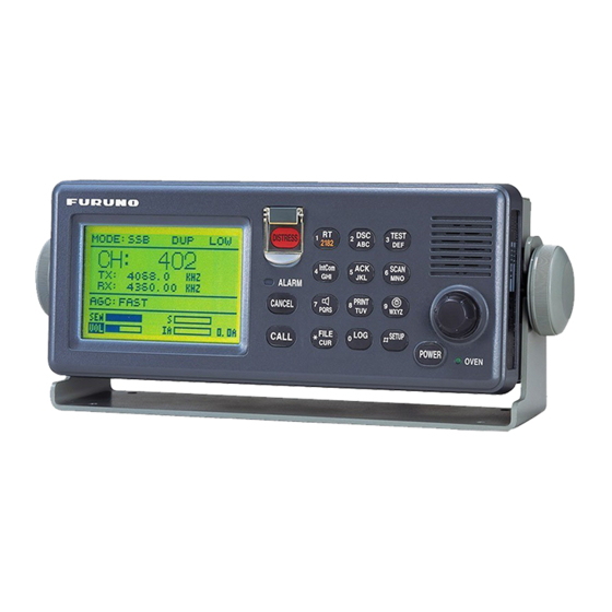
- Page 1 SSB RADIOTELEPHONE FS-1570 (150 W) FS-2570 (250 W)
- Page 2 *00080933800* *00080933800* *00080933800* *00080933800* ( ( DAMI DAMI ) ) FS-1570/2570 FS-1570/2570 * 0 0 0 8 0 9 3 3 8 0 0 * * 0 0 0 8 0 9 3 3 8 0 0 * *OME56360Z00* *OME56360Z00*...
- Page 3 DISTRESS Call Procedure Do the following when a life-endangering situation arises on your vessel. 1. Open the DISTRESS button cover and press the [DISTRESS] button more than three seconds to show the following display, then release the [DISTRESS] button. Distress call in progress! NATURE: UNDESIGNATED POS:...
- Page 4 Wire Indoor the equipment. Antenna Wire (High Voltage) Continued use of the equipment can cause Lead-in fire or electrical shock. Contact a FURUNO Insulator Antenna agent for service. (High Coupler Voltage) Do not disassemble or modify the equipment.
- Page 5 Do not remove the labels. situation on your vessel. If a label is missing or illegible, contact a FURUNO agent or dealer If the distress alert is accidentally about replacement. transmitted, contact the nearest coast...
-
Page 6: Table Of Contents
TABLE OF CONTENTS FOREWORD......................ix SYSTEM CONFIGURATION ................xi OPERATIONAL OVERVIEW ...............1-1 1.1 Controls ........................1-1 1.2 Turning the Power On/Off................... 1-2 1.3 Panel Dimmer, LCD Contrast ..................1-2 1.4 Indications........................1-3 1.4.1 DSC standby screen ..................1-3 1.4.2 Radiotelephone screen ................. 1-3 1.5 Loudspeaker ...................... - Page 7 DSC OVERVIEW..................3-1 3.1 What is DSC?......................3-1 3.2 DSC Call ........................3-1 3.2.1 Distress alert call and reply................3-3 3.2.2 Individual call....................3-4 3.3 Audio Alarms ......................3-4 3.4 Interpreting Call Displays....................3-5 3.4.1 Receive calls ....................3-5 3.4.2 Send calls......................3-7 DISTRESS OPERATIONS ................4-1 4.1 Sending Distress Alert ....................4-1 4.1.1 Sending distress alert by DISTRESS button, nature of distress not specified ....................4-1 4.1.2 Sending distress alert by DISTRESS button, nature of distress specified ..4-3...
- Page 8 5.8 Position Call ......................5-33 5.8.1 Position call: requesting other ship’s position ..........5-34 5.8.2 Position call: other ship requests your position ..........5-36 5.9 PSTN Call ........................ 5-38 5.9.1 Sending a PSTN call, receiving acknowledge back (ACK BQ) ......5-38 5.9.2 Receiving a PSTN call, sending acknowledge back (ACK BQ)....
- Page 9 NBDP PREPARATIONS ................9-1 9.1 Registering Answerback Code & ID Codes..............9-1 9.1.1 Registering answerback code................9-1 9.1.2 Registering ID codes ..................9-2 9.2 Station List........................9-3 9.2.1 Registering stations ..................9-3 9.2.2 Editing/Deleting stations ................9-4 9.3 Timer Programming ....................9-5 9.3.1 Registering timer programs ................9-5 9.3.2 Editing/Deleting timer programs..............9-6 9.4 User Channels......................9-6 9.4.1 Registering user channels ................9-6 9.4.2 Editing/Deleting user channels ..............9-7...
- Page 10 11.6 FEC Mode Operation....................11-7 11.7 Communication Example..................11-8 11.8 Timer Operation.....................11-11 11.8.1 Enabling timer operation................11-11 11.8.2 Stopping timer operation................11-11 11.9 Scanning .......................11-12 11.10 Communication Buffer ..................11-12 12 MAINTENANCE & TROUBLESHOOTING..........12-1 12.1 Daily Test ....................... 12-1 12.2 Radiotelephone Test....................12-2 12.3 Antenna Coupler Test .....................
-
Page 11: Foreword
FOREWORD Thank you for purchasing the FS-1570 (150 W)/FS-2570 (250 W) SSB Radiotelephone. We are confident you will discover why FURUNO has become synonymous with quality and reliability. Dedicated in the design and manufacture of marine electronics equipment for over half a century, FURUNO Electric Company has gained an unrivaled reputation as a world leader in the industry. - Page 12 DSC/watch receiver • Distress, safety and routine communications • Scanning of DSC frequencies for distress and general calls on MF/HF • File editing capability for readiness in case of emergency • PSTN (Public Switched Telephone Network) capability standard • Log stores 50 each of latest ordinary, distress and transmitted messages, in separate memory blocks.
-
Page 13: System Configuration
SYSTEM CONFIGURATION FS-2570 (250 W) PREAMP Antenna Coupler PREAMP AT-1560-25 FAX-5 FAX-5 LOUDSPEAKER SEM-21Q NAVIGATOR RX BOARD CONTROL UNIT HANDSET CONTROLLER 1 FS-2570C HS-2001 INCOMING INDICATOR PRINTER IC-303-DSC PP-510 TRANSCEIVER NBDP TERMINAL UNIT UNIT IB-581/582/IB-583 FS-2570T PRINTER TELEX DISTRESS SWITCH BOX ALERT BUTTON Note: The CONTROL IC-302-DSC... - Page 14 FS-1570 (150 W) PREAMP Antenna Coupler FAX-5 AT-1560-15 LOUDSPEAKER SEM-21Q NAVIGATOR HANDSET CONTROL UNIT CONTROLLER 1 HS-2001 FS-2570C INCOMING INDICATOR PRINTER IC-303-DSC PP-510 TRANSCEIVER NBDP TERMINAL UNIT UNIT IB-581/IB-582/IB-583 TELEX DISTRESS FS-1570T PRINTER ALERT BUTTON SWITCH BOX IC-302-DSC Note: The CONTROL...
-
Page 15: Operational Overview
OPERATIONAL OVERVIEW 1.1 Controls FURUNO TEST DISTRESS 2182 IntCom ACK/SQ SCAN PUSH TO ENTER ALARM PRINT CANCEL WXYZ PQRS FILE # SETUP CALL CURSOR TUNE POWER OVEN ENTER knob Description of controls Control Function POWER switch Turns the power on/off. -
Page 16: Turning The Power On/Off
1 OPERATIONAL OVERVIEW • Turns loudspeaker on/off. • Note that this key does not silence the distress or urgency alarm. 8/PRINT key Prints communications log files, current screen (except DSC standby screen and radiotelephone screen) and test results. Adjusts panel dimmer and LCD contrast. •... -
Page 17: Indications
1 OPERATIONAL OVERVIEW 1.4 Indications 1.4.1 DSC standby screen The DSC standby screen may be displayed by using the [6/SCAN] key. This is where you begin all calling operations. Acknowledge status (AUTO ACK or MANUAL ACK) WATCH KEEPING AUTO ACK DISTRESS Distress and routine frequencies 2187.5... -
Page 18: Loudspeaker
1 OPERATIONAL OVERVIEW 1.5 Loudspeaker 1. Press the [7/ ] key to alternately disable or enable the loudspeaker and the alarm generated for routine messages. SOUND: ON or SOUND: OFF appears with each press. 2. To adjust loudspeaker volume do the following: Press the [1/RT 2182] key to show the radiotelephone screen. -
Page 19: Manual Entry Of Position And Time
1 OPERATIONAL OVERVIEW 1.8 Manual Entry of Position and Time If there is no EPFS (Electronic Position-Fixing System) connected to this equipment or the EPFS connected is not working (EPFS error indication appears), manually enter position and time as follows: 1. - Page 20 1 OPERATIONAL OVERVIEW 5. Push the [ENTER] knob to open the latitude input window. Use the numeric keys to enter latitude. If necessary, switch coordinates: [1] key to switch to North; [2] key to switch to South. Push the [ENTER] knob. Position setup INPUT TYPE: MANUAL 34 °...
-
Page 21: System Characteristics
1 OPERATIONAL OVERVIEW 1.9 System Characteristics 1.9.1 Equipment priority Equipment priority order is as below. 1. DMC 2. Each control unit and control unit sending distress alert 3. Control unit 1 – routine use 4. Control unit 2 – routine use 5. -
Page 22: Automatic Setting Of Working Frequency
1 OPERATIONAL OVERVIEW 1.9.4 Automatic setting of working frequency The radiotelephone automatically sets working frequency in the following conditions: • ABLE ACK is sent in response to individual call. • Your ship receives ABLE ACK in response to own ship-initiated individual call. •... -
Page 23: Power Supply Unit (Option)
(115 or 230 VAC). The power supply unit is type PR-300, supplying 24 VDC power (20 A) to the FS-1570 or type PR-850A, supplying 24 VDC (40 A) to the FS-2570. Both 115/230 VAC and 24 VDC power can be connected simultaneously. In this case, the system normally operates on the AC mains supply and when AC power is lost, the PSU automatically switches to the DC power source. - Page 24 1 OPERATIONAL OVERVIEW (This page intentionally left blank.) 1-10...
-
Page 25: Ssb Radiotelephone
SSB RADIOTELEPHONE You can enter desired frequency by channel or TX and RX frequencies. The handset may be ON HOOK or OFF HOOK. Note: To set the SSB radiotelephone to 2182 kHz/J3E, press the [1/ RT/2182] key more than two seconds. 2.1 Transmitting After selecting class of emission and frequency, you can transmit by pressing the PTT switch on the handset. -
Page 26: Choosing Channel, Frequency
2 SSB RADIOTELEPHONE 2.1.2 Choosing channel, frequency Choosing channel 1. Rotate the [ENTER] knob to choose CH and then push the [ENTER] knob. MODE: SSB SIMP HIGH CH: 800 TX: 2182.0 RX: 2182.00 AGC : FAST 0.0A 2. Channel can be entered directly with the numeric keys, or by using the [ENTER] knob. See below for details. -
Page 27: Tuning
2 SSB RADIOTELEPHONE Choosing frequency 1. Rotate the [ENTER] knob to choose TX or RX as appropriate and then push the [ENTER] knob. MODE: AM SIMP HIGH CH: 200 TX: 2182.0 2182.00 KHZ 123456.78 AGC : SLOW 0.0A 2. Enter frequency by one of the methods below. Entering frequency with the numeric keys: Use the numeric keys to enter frequency and then push the [ENTER] knob. -
Page 28: Using The Handset
2 SSB RADIOTELEPHONE Note: When tuning is initiated in the two-control unit system, the display of the idle control unit shows “OCCUPIED(ANOTHER CONTROLLER).” In this case, only the DISTRESS button is operative on the idle control unit. Further, if a control unit is in use when tuning is attempted at the other control unit, the display of the control unit which attempted to tune shows “OCCUPIED”... -
Page 29: Reducing Transmitter Power
This should be done when using the transceiver in a harbor, near the shore or close to communication partner (other ship). 1. Rotate the [ENTER] knob to choose LOW, MID or HIGH (whichever is shown) at the top of the screen and then push the [ENTER] knob. FS-1570 FS-2570 MODE: SSB SIMP... -
Page 30: Receiving
2 SSB RADIOTELEPHONE 2.2 Receiving 2.2.1 RF gain (sensitivity) adjustment In normal use the sensitivity should be set for maximum. If the audio on the received channel is unclear or interfered with other signals, adjust (usually reduce) sensitivity to improve clarity. 1. -
Page 31: Squelch Control, Squelch Frequency
2 SSB RADIOTELEPHONE MODE: AM SIMP HIGH CH: 200 TX: 2182.0 2182.00 KHZ 123456.78 AGC : SLOW 0.0A 5. Key in RX frequency with the numeric keys and then push the [ENTER] knob. 2.2.5 Squelch control, squelch frequency Squelch on/off The squelch mutes the audio output in the absence of an incoming signal. -
Page 32: Intercom
2 SSB RADIOTELEPHONE 2.3 Intercom The built-in intercom permits voice communications between two FS-2570C Control Units. 1. Press the [1/ RT/2182] key to show the radiotelephone screen. 2. Off hook the handset. 3. Press the [4/IntCom] key to show INTERCOM on the display. 4. -
Page 33: In The Event Of Antenna Coupler Failure
2 SSB RADIOTELEPHONE 2.5 In the Event of Antenna Coupler Failure The antenna coupler automatically tunes a wire or whip antenna to the transceiver. When all frequencies cannot be tuned, TUNE OK will not appear on the display. In this case, you can tune 2182 kHz by manually operating the coupler as shown in the procedure below. -
Page 34: User Channels
2.6 User Channels The USER CH menu allows registration of user TX and RX channels, where permitted by the Authorities. NOTICE FURUNO will assume no responsibility for the disturbance caused by the unlawful or improper setting of user channels. 2.6.1 Registering user channels “USER CH”... - Page 35 2 SSB RADIOTELEPHONE User ch entry " MODE: 2-01 00201. TX: 2111.5 RX: 2111.5 NBDP 00202. TX: 2222.0 RX: 2222.0 00203. TX: 2333.5 RX: 2333.5 00204. TX: 2444.0 RX: 2444.0 00205. TX: 2555.5 RX: 2555.5 DOWN 6. Rotate the [ENTER] knob to choose appropriate mode among SSB, NBDP and DSC and then push the [ENTER] knob.
-
Page 36: Deleting User Channels
2 SSB RADIOTELEPHONE 2.6.2 Deleting user channels Deleting individual user channels 1. At the radiotelephone screen, press the [#/SETUP] key. 2. Rotate the [ENTER] knob to choose USER CH and then push the [ENTER] knob. 3. Rotate the [ENTER] knob to choose ENTRY and then push the [ENTER] knob. 4. -
Page 37: Dsc Overview
2187.5, 4207.5, 6312.0, 8414.5, 12577.0, and 16804.5. The DSC station sends and receives DSC general and safety calls via the radiotelephone. DSC call TX Routine DSC call TX Distress, Safety and Routine General DSC Call DSC Calls FS-1570 Option FS-2570 CONTROL UNIT (FS-2570 only) FS-2570C 3.2 DSC Call... - Page 38 DSC OVERVIEW Contents of a non-distress, safety DSC call • Calling category Call category Call Individual Individual, PSTN, Test, Position, Polling, Relay Sel (specific coast station) All Ships All Ships, Neutral, Medical, Relay All Group Group Geographical Area Area • Station ID Own ship ID and sending station ID.
-
Page 39: Distress Alert Call And Reply
3 DSC OVERVIEW 3.2.1 Distress alert call and reply This type of call is sent by own ship in the event of distress, by using the [DISTRESS] button as follows: 1. The LED in the [DISTRESS] button initially flashes, and lights when the button is pressed more than three seconds. -
Page 40: Individual Call
DSC OVERVIEW 3.2.2 Individual call The individual call is for sending a call to a specific station. (1) DSC Message [Called Acknowledge Request (ACK RQ) Signal] Coast (2) Acknowledge Back (ACK BQ) Signal Own Ship Station (3) Voice or telex communication Basic procedure (radiotelephone) 1. -
Page 41: Interpreting Call Displays
3 DSC OVERVIEW 3.4 Interpreting Call Displays This paragraph provides the information necessary for interpreting receive and send call displays. 3.4.1 Receive calls Below are sample distress and individual receive calls. The content of other types of receive calls is similar to that of the individual call. Distress receive call Date and time of message Received message... - Page 42 DSC OVERVIEW Individual receive call Received message Date and time of message ECC (Error Check Character): OK or NG (No Good) MAR-23-2002-23:59 ECC: OK Able acknowledge ("Unable acknowledge" and reason if unable) INDIVIDUAL REQUEST ID No. of sending station FROM SHIP: 123456789 Category (Routine, Business, Safety, Urgency) ROUTINE...
-
Page 43: Send Calls
3 DSC OVERVIEW 3.4.2 Send calls Below are sample distress and individual send calls. The content of other types of send calls is similar to that of the individual call. Distress send call Distress call in progress! Nature of Distress (Undesignated, Fire, Flooding, NATURE: UNDESIGNATED Collision, Grounding, Listing, Sinking, Disable, POS:... - Page 44 DSC OVERVIEW (This page intentionally left blank.)
-
Page 45: Distress Operations
DISTRESS OPERATIONS 4.1 Sending Distress Alert GMDSS ships carry a DSC terminal with which to transmit the distress alert in the event of a life-endangering situation. A coast station receives the distress alert and sends the distress alert acknowledge call to the ship in distress. Then, voice or telex communications between the ship in distress and coast station begins. - Page 46 4 DISTRESS OPERATIONS 2. The display changes as below. It takes about 40 seconds to transmit the distress alert, and the number of seconds until transmission is completed is shown at the bottom of the display. At this time the output power of the radiotelephone is automatically set to maximum.
-
Page 47: Sending Distress Alert By Distress Button, Nature Of Distress Specified
4 DISTRESS OPERATIONS Received message JAN-23-2002-23:59 ECC: OK DISTRESS ACKNOWLEDGE FROM COAST: 001234567 SHIP IN DIST: 123456789 NATURE: UNDESIGNATED 12 ° 34N 123 ° 45E AT 12:34 POS: TELEPHONE 2182.0 KHZ GO TO ALL VIEW 6. Communicate with the coast station via radiotelephone, following the instructions below. - Page 48 4 DISTRESS OPERATIONS 4. Push the [ENTER] knob to open the INPUT TYPE menu. INPUT TYPE: AUTO AUTO ° LAT : 34 41 NORTH MANUAL ° LON : 135 30 EAST NO INFO TIME: 09: 00 UTC 5. Rotate the [ENTER] knob to choose MANUAL and then push the [ENTER] knob. If you cannot confirm your position, choose NO INFO, push the [ENTER] knob and then go to step 10.
- Page 49 4 DISTRESS OPERATIONS 10. The COMPOSE MESSAGE screen is redisplayed. Push the [ENTER] knob to open the COM. TYPE menu. Compose message DISTRESS CALL TYPE: NATURE: FLOODING TELEPHONE ° POS: 35 N 135˚00E AT 23:25 NBDP-FEC COM. TYPE: TELEPHONE DSC FREQ : 2187.5 KHZ GO TO ALL VIEW 11.
-
Page 50: Receiving A Distress Alert
ABC-12M Mode : ARQ FEC ABC-8M Tx Freq : 2174.50 FURUNO Rx Freq : 2174.50 3. DSC is selected; press the [Enter] key. 4. Confirm that “Connect” is highlighted, then type your message, giving the following information: a) Ship’s name and call sign... - Page 51 4 DISTRESS OPERATIONS Action for ship receiving distress alert on MF band DSC Distress alert received. Press [CANCEL] key to silence alarm. Listen on VHF 2182 kHz for 5 minutes. Did you receive Is the DSC distress Is distress traffic acknowledge from CS and/or RCC? call continuing?
- Page 52 4 DISTRESS OPERATIONS 2. Press the [CANCEL] key to silence the audio alarm, and the display changes as below. Received message JAN-23-2002-23:59 ECC: OK DISTRESS CALL ID IN DIST: 123456789 NATURE: UNDESIGNATED POS: 12˚34N 123˚45E AT 12:34 TELEPHONE ! " 8414.5 KHZ ANSWER ALL VIEW...
-
Page 53: Distress Alert Received On Hf Band
4 DISTRESS OPERATIONS 4.2.2 Distress alert received on HF band If you receive a distress alert on the HF band, the ALARM lamp lights and the audio alarm sounds. Press the [CANCEL] key to silence the audio alarm. Wait for the distress acknowledge from a coast station. - Page 54 4 DISTRESS OPERATIONS Sending the distress relay to coast station (on HF band) 1. The audio alarm sounds and the display changes as below when a distress call is received. Distress call received. DISTRESS CALL ID IN DIST: 123456789 NATURE: UNDESIGNATED POS: 12˚34N 123˚45E AT 12:34 TELEPHONE...
- Page 55 4 DISTRESS OPERATIONS 7. Push the [ENTER] knob to open the DSC FREQ. menu. Compose message 2187.5 CALL TYPE : ALL SHIPS 4207.5 DISTRESS RELAY 6312.0 COAST ID: 8414.5 ID IN DIST : 12577.0 16804.5 DSC FREQ GO TO EASY VIEW GO TO ALL VIEW 8.
-
Page 56: Sending Distress Relay On Behalf Of A Ship In Distress
4 DISTRESS OPERATIONS 4.3 Sending Distress Relay on Behalf of a Ship in Distress 4.3.1 Sending distress relay to coast station You may send the distress relay to a coast station on behalf of a ship in distress in the following cases: •... - Page 57 4 DISTRESS OPERATIONS 7. Push the [ENTER] knob to open the NATURE menu. Rotate [ENTER] knob to scroll. Compose message CALL TYPE : All ships UNDESIGNATED COAST ID FIRE SINKING ID IN DIST FLOODING : 987654321 DISABLE COLLISION NATURE :Undesignated ABANDONING GROUNDING POS: ION.
- Page 58 4 DISTRESS OPERATIONS Compose message 2187.5 CALL TYPE : ALL SHIPS 4207.5 DISTRESS RELAY 6312.0 COAST ID: 8414.5 SHIP IN DIST : 12577.0 16804.5 DSC FREQ GO TO EASY VIEW GO TO ALL VIEW 12. Rotate the [ENTER] knob to choose appropriate DSC (NBDP) frequency and then push the [ENTER] knob.
-
Page 59: Sending Distress Relay To All Ships
4 DISTRESS OPERATIONS 15. When you receive the distress relay acknowledge call, the audio alarm sounds and the display shown below appears. Distress relay ack call received. COAST ID : 001234567 ID IN DIST : NO INFO NATURE : SINKING POS : 12°34N 123°45E AT 12:34 TELEPHONE... - Page 60 4 DISTRESS OPERATIONS Compose message CALL TYPE : All ships UNDESIGNATED FIRE ID IN DIST FLOODING : 987654321 NATURE COLLISION :Undesignated POS: ION. GROUNDING COM.TYPE LISTING DSC FREQ 6. Rotate the [ENTER] knob to choose nature of distress and then push the [ENTER] knob.
- Page 61 4 DISTRESS OPERATIONS 11. Push the [ENTER] knob to open the DSC FREQ menu. Compose message CALL TYPE: RELAY ALL 2187.5 ID IN DIST: 123456789 4207.5 NATURE : UNDESIGNATED 6312.0 8414.5 POS: 34˚45N 135˚45E AT 9:30 COM TYPE: 12577.0 16804.5 DSC FREQ GO TO EASY VIEW GO TO ALL VIEW...
-
Page 62: Receiving Distress Relay All Ships
4 DISTRESS OPERATIONS 4.4 Receiving Distress Relay All Ships When you receive a distress relay for all ships, continue monitoring distress and safety frequencies. 1. The audio alarm sounds and the display looks like the one below when a distress relay all ships call is received. -
Page 63: Calling, Receiving
CALLING, RECEIVING This chapter provides the information necessary for general calling and receiving. 5.1 All Ships Call When an urgent but not life-endangering situation arises on your ship, for example, engine trouble, send an all ships call to request assistance. After sending the call, you can communicate by voice over the radiotelephone, or send a message by telex. - Page 64 5 CALLING, RECEIVING 3. Push the [ENTER] knob to display the PRIORITY menu. Compose message CALL TYPE: ALL SHIPS SAFETY PRIORITY URGENCY COM. TYPE : TELEPHONE DISTRESS DSC FREQ 2187.5 KHZ GO TO ALL VIEW 4. Rotate the [ENTER] knob to choose SAFETY or URGENCY as appropriate and then push the [ENTER] knob.(DISTRESS should be used only when there is a life endangering situation on board your vessel.) 5.
-
Page 65: Receiving An All Ships Call
5. CALLING, RECEIVING Communicating by NBDP Terminal Unit 1. Press the function key [F3] on the keyboard of the NBDP Terminal Unit to show the Operate menu. 2. Call Station is selected; press the [Enter] key. 3. DSC is selected; press the [Enter] key. 4. -
Page 66: Individual Call
5 CALLING, RECEIVING 5.2 Individual Call The individual call is for calling a specific station. After sending an individual call, called ACK RQ transmission, wait to receive the acknowledge back (ACK BQ) signal from the receiving station. 5.2.1 Sending an individual call 1. - Page 67 5. CALLING, RECEIVING 6. Rotate the [ENTER] knob to choose appropriate priority (normally ROUTINE) and then push the [ENTER] knob. 7. Push the [ENTER] knob to open the COM. TYPE menu. Routine or For Safety or Business Priority Urgency Priority Compose message MAIN TELEPHONE...
- Page 68 5 CALLING, RECEIVING How to Set Working Frequency, Channel To send a call, set the working frequency as below, to communicate with the receiving station. The working frequency can be entered by Tx and Rx frequencies or channel number. Routine or ship's business priority 1.
- Page 69 5. CALLING, RECEIVING How to Set DSC Frequency Routine or ship’s business priority 1. Rotate the [ENTER] knob to choose DSC FREQ and then push the [ENTER] knob. Compose message Rotate the [ENTER] CALL TYPE INDIVIDUAL 2 MHZ : Individual 16 MHZ knob to scroll.
- Page 70 5 CALLING, RECEIVING 12. Press the [CALL] key to send the individual call (transmission time: about 7 sec.). The display shows the message "Individual request call in progress!" while the call is being sent. Individual request Note: When the channel is in use, call in progress! "CH BUSY"...
- Page 71 5. CALLING, RECEIVING Able acknowledge call received Communicating by radiotelephone The audio alarm sounds; press the [CANCEL] key to silence it, and the display changes as below. Press the [CANCEL] key to return to the DSC standby screen. The working frequency is automatically set;...
-
Page 72: Receiving An Individual Call
5 CALLING, RECEIVING 5.2.2 Receiving an individual call Sending automatic acknowledge (ACK BQ) with comply type “ABLE” When own ship receives an individual call, you may or may not be able to receive the call depending on the comply-type setting (on the Auto Ack menu). The relationship between comply type and automatic/manual acknowledge is as shown in the table below. - Page 73 5. CALLING, RECEIVING Communicating by NBDP Terminal Unit After acknowledging an individual call, do the following to send a message by NBDP Terminal Unit. 1. After the able acknowledge call is transmitted, the display shows “OCCUPIED” and the TX and RX frequencies. 2.
- Page 74 5 CALLING, RECEIVING 5. If you want to send a proposal, rotate the [ENTER] knob to choose RE-SEND and then push the [ENTER] knob. Compose message CALL TYPE : INDIVIDUAL STATION ID : 001234567 PRIORITY : ROUTINE COM. TYPE : TELEPHONE COM.
- Page 75 5. CALLING, RECEIVING Compose message CALL TYPE: ABLE ACKNOWLEDGEMENT TO COAST: 121234567 COM. TYPE: TELEPHONE COM. FREQ: CH12034 DSC FREQ: 12577.5 KHZ GO TO ALL VIEW 5. Press the [CALL] key to send the call. The display changes as below. Able acknowledge call in progress! TO COAST...
- Page 76 5 CALLING, RECEIVING Manually acknowledging individual call with “UNABLE” 1. When an individual call is received, the alarm sounds and the display shows the message "Individual request call received." Individual request call received. FROM SHIP: 121234567 ROUTINE TELEPHONE CH 12034 STOP ALARM 2.
-
Page 77: Group Call
5. CALLING, RECEIVING Compose message CALL TYPE : UNABLE ACKNOWLEDGEMENT REASON : CHANNEL NOT USABLE TO SHIP : 121234567 DSC FREQ 12577.5 KHZ GO TO ALL VIEW 9. Press the [CALL] key to send the call. The display shows "Unable acknowledge call in progress!"... - Page 78 5 CALLING, RECEIVING Compose message : GROUP CALL CALL TYPE GROUP ID 000000000 : ROUTINE PRIORITY : TELEPHONE COM. TYPE : NO INFO COM. FREQ : 2M-INTL DSC FREQ GO TO ALL VIEW 4. Key in group ID (nine digits) with the numeric keys and then push the [ENTER] knob. 5.
- Page 79 5. CALLING, RECEIVING 10. Rotate the [ENTER] knob to choose communication frequency desired and then push the [ENTER] knob. (See page 5-6 for details.) NO INFO lets other party choose communication frequency. 11. Push the [ENTER] knob to open the DSC FREQ menu. Compose message CALL TYPE : Individual...
-
Page 80: Receiving A Group Call
5 CALLING, RECEIVING 5.3.2 Receiving a group call Group ID must be registered in order to receive a group call. See paragraph 6.2. 1. The audio alarm sounds and the display shows "Group call received" when a group call is received. Group call received. -
Page 81: Geographical Area Call
5. CALLING, RECEIVING 5.4 Geographical Area Call The geographical area call is for sending a call to all ships within the area you designate in your geographical area call. In the figure below, for example, the call will be sent to all ships within 24-34°N, 135-140°W. - Page 82 5 CALLING, RECEIVING 5. Push the [ENTER] knob to open the PRIORITY menu. Compose message CALL TYPE : AREA CALL ROUTINE 12 ° N 123 ° W ↓12 ° → 12 ° AREA : SAFETY PRIORITY : Routine URGENCY COM. TYPE : Telephone COM.
- Page 83 5. CALLING, RECEIVING 11. Push the [ENTER] knob to open the DSC FREQ menu. Rotate the [ENTER] Compose message knob to scroll. CALL TYPE: Individual 2 MHZ 4 MHZ 16 MHZ AREA: 001234567 18 MHZ 6 MHZ PRIORITY : Routine 22 MHZ 8 MHZ COM.
-
Page 84: Receiving A Geographical Area Call
5 CALLING, RECEIVING 5.4.2 Receiving a geographical area call 1. The alarm sounds and the display shows "Geographical area call received" when a geographical area call is received. Geographical area call received. FROM SHIP: 123456789 ROUTINE TELEPHONE 12264.0 KHZ STOP ALARM 2. -
Page 85: Neutral Craft Call
5. CALLING, RECEIVING 5.5 Neutral Craft Call The neutral craft call, which contains own ship position and ID, informs all ships that your ship is not a participant in armed conflict. Send the call BEFORE entering an area of armed conflict. - Page 86 5 CALLING, RECEIVING Compose message CALL TYPE : NEUTRAL CRAFT PRIORITY : SAFETY COM. TYPE : TELEPHONE DSC FREQ 2187.5 KHZ GO TO ALL VIEW 9. Press the [CALL] key to send the neutral craft call (transmission time: approx. 7 sec.). Neutral craft call in progress! SAFETY...
-
Page 87: Receiving A Neutral Craft Call
5. CALLING, RECEIVING 5.5.2 Receiving a neutral craft call 1. When a neutral craft call is received the alarm sounds and the display changes as below. Neutral craft call received. FROM SHIP: 123456789 SAFETY TELEPHONE 2182.0 KHZ STOP ALARM 2. Press the [CANCEL] key to silence the alarm. The display changes as below. Received message MAR-23-2002-23:59 ECC: OK... -
Page 88: Medical Transport Call
5 CALLING, RECEIVING 5.6 Medical Transport Call The medical transport call informs all ships, by urgency priority, that own ship carries medical supplies. 5.6.1 Sending a medical transport call 1. Press the [2/DSC] key and then push the [ENTER] knob to open the CALL TYPE menu. Compose message Rotate [ENTER] knob to scroll. -
Page 89: Receiving A Medical Transport Call
5. CALLING, RECEIVING Medical transport call in progress! URGENCY TELEPHONE 2182.0 KHZ DSC FREQ : 2187.5 KHZ TIME TO GO : 8. After the call is sent the radiotelephone screen automatically appears. Inform all ships (by radiotelephone) that your ship is transporting medical supplies. For NBDP do the following: Sending message by NBDP Terminal Unit 1. -
Page 90: Polling Call
5 CALLING, RECEIVING In case of NBDP Terminal Unit After receiving a neutral craft call, do the following to watch by NBDP Terminal Unit. 1. The display shows “OCCUPIED” and the TX and RX frequencies. 2. The message from the sending station appears on your NBDP Terminal Unit. 5.7 Polling Call Polling means confirming if own station is within communicating range with other station. - Page 91 5. CALLING, RECEIVING Compose message CALL TYPE : Polling ROUTINE STATION ID : 987654321 BUSINESS : Routine PRIORITY SAFETY : 12M-INTL URGENCY DSC FREQ GO TO ALL VIEW 6. Rotate the [ENTER] knob to choose priority desired (usually ROUTINE) and then push the [ENTER] knob.
- Page 92 5 CALLING, RECEIVING 10. After the call is sent, the following display appears. Waiting for polling acknowledgement. FROM SHIP: 123456789 ROUTINE DSC FREQ : 2177.0 KHZ TIME TO GO: 4M59S 11. The timer counts down the time remaining to wait for acknowledgment of the call. One of the following displays appears.
-
Page 93: Receiving A Polling Call
5. CALLING, RECEIVING 5.7.2 Receiving a polling call Automatic reply 1. The display changes as shown in the illustration below and the audio alarm sounds when a polling request call is received and the equipment is set up for automatic acknowledge. - Page 94 5 CALLING, RECEIVING Manual reply 1. The display changes as shown in the illustration below and the audio alarm sounds when a polling request call is received and the status of the [5/ ACK/SQ] key is MANUAL ACK. Polling request call received.
-
Page 95: Position Call
5. CALLING, RECEIVING 5.8 Position Call There are two types of position calls: other station requires your ship’s position and your ship requests position of another ship. Finding position of other station (1) Position Information (2) Position request call Own Station Other Station Sending own ship's position to other stations Position Information... -
Page 96: Position Call: Requesting Other Ship's Position
5 CALLING, RECEIVING 5.8.1 Position call: requesting other ship’s position 1. Press the [2/DSC] key and then push the [ENTER] knob to open the CALL TYPE menu. Compose message Rotate [ENTER] knob to scroll. INDIVIDUAL PSTN CALL : All ships CALL TYPE TEST CALL : Safety... - Page 97 5. CALLING, RECEIVING 9. The display now looks something like the illustration below. Compose message CALL TYPE: POSITION REQUEST STATION ID 123456789 PRIORITY : ROUTINE DSC FREQ : 2177.0 KHZ GO TO ALL VIEW 10. Press the [CALL] key to send the call (transmission time: about 7 sec.). The following display appears.
-
Page 98: Position Call: Other Ship Requests Your Position
1. When another ship requests your position and the status of the [5/ ACK/SQ] key is AUTO ACK and the setting of POSITION CALL on the Auto ack menu is ON, the FS-1570/2570 transmits own position data (transmission time: approx. 7 sec.), showing the display below. - Page 99 5. CALLING, RECEIVING 3. Press the [CANCEL] key to silence the alarm, and the display changes as below. Xmitted message MAR-23-2002-23:59:09 POSITION ACKNOWLEDGE TO SHIP : 987654321 ROUTINE ° ° POS : 35 00N 135 00E AT 23:59 GO TO ALL VIEW 4.
-
Page 100: Pstn Call
5 CALLING, RECEIVING 4. Confirm your position and then press the [CALL] to send the position data call (transmission time: approx. 7 sec.). The display changes as below. Pos acknowledge call in progress! TO SHIP : 123456789 ROUTINE POS: 35˚00N 135˚00E AT 23:01 DSC FREQ 2177.0 KHZ TIME TO GO:... - Page 101 5. CALLING, RECEIVING 4. Key in ID of coast station (nine digits) with the numeric keys and then push the [ENTER] knob. Note: If you have registered some coast IDs (Chapter 6) you can insert a desired telephone number in your message as follows: 1.
- Page 102 5 CALLING, RECEIVING PSTN request call in progress! TO COAST : 001234567 TEL NO. 1234567890123456 DSC FREQ : 2189.5 KHZ TIME TO GO: 10. One of the following three displays appears. (“No response. Try calling again.” Appears after timer counts down to zero and it means there was no response from the coast station.) Waiting for Unable acknowledge...
- Page 103 5. CALLING, RECEIVING PSTN call connected. Waiting for PSTN end of call acknowledgement. in progress! TO COAST : FROM COAST : 001234567 001234567 TO COAST : 001234567 TEL NO. TEL NO. 1234567890123456 1234567890123456 TEL NO. 1234567890123456 TELEPHONE CH 12001 TELEPHONE CH 12001 DSC FREQ : 12230.0 KHZ...
-
Page 104: Receiving A Pstn Call, Sending Acknowledge Back (Ack Bq)
5 CALLING, RECEIVING 5.9.2 Receiving a PSTN call, sending acknowledge back (ACK BQ) 1. The following display appears when a PSTN call is received. Able acknowledge call in progress! TO COAST : 001234567 TEL NO. 1234567890123456 TELEPHONE CH 12001 DSC FREQ : 12577.5 KHZ TIME TO GO: 2. -
Page 105: Pstn Call Disconnection, Receiving Charge Information (Ship Disconnects Line)
5. CALLING, RECEIVING 5. Shortly thereafter, one of the following messages appears. PSTN call connected. PSTN connection PSTN end of call call in progress! in progress! TO COAST : 001234567 FROM COAST : TO COAST : 001234567 001234567 TEL NO. 1234567890123456 TEL NO. -
Page 106: Pstn Call Disconnection, Receiving Charge Information (Coast Station Disconnects Line)
5 CALLING, RECEIVING Charge information No response! call received. charge information. CHARGE TIME : 00H 12M 34S FROM COAST : 001234567 FROM COAST : 001234567 TEL NO. 1234567890123456 TEL NO. 1234567890123456 STOP ALARM 4. For “No response! charge information.”, the equipment reverts to step 2 in this procedure to await charge information. -
Page 107: Log File
5. CALLING, RECEIVING 5.10 Log File Three log files are provided for storage of calls: received ordinary log, received distress log and transmitted log. Each log file stores 50 calls, on a first-in, first-out basis. This means that the latest call is saved as log no.1 and the log no. of all previous calls in that log increments by one. - Page 108 5 CALLING, RECEIVING 4. To scroll the log up and down, use the [FILE/CURSOR] and [#/SETUP] keys, respectively. 5. To print selected file, press the [8/PRINT] key. 6. To reply to an unanswered call, rotate the [ENTER] knob to choose ANSWER and then press the [CALL] key.
-
Page 109: Preparing Tx Calls
PREPARING TX CALLS In Chapter 5 you learned how to prepare and send various types of DSC calls. In this chapter you will learn how to prepare and store individual, PSTN, group, area and test calls for future transmission. 150 calls can be stored. 6.1 Preparing Individual Calls 1. - Page 110 6 PREPARING TX CALLS 9. Push the [ENTER] knob to open the COM. FREQ window. Message file entry CALL TYPE: INDIVIDUAL STATION ID : 123456789 NO INFO COM. TYPE : TELEPHONE FREQUENCY COM. FREQ : NO INFO CHANNEL DSC FREQ : 2M-INTL POSITION* * POSITION appears when...
- Page 111 FILE ENTRY 2. Use the numeric keys and [ENTER] knob to enter file name (max. 16 characters) and press the [ENTER] knob. For example, enter FURUNO as the file name. How to assign file name How to enter "FURUNO" as file name [1_] key : 1→_→1...
-
Page 112: Preparing Group Calls
6 PREPARING TX CALLS 6.2 Preparing Group Calls 1. At the DSC standby screen, press the [#/SETUP] key to open the Setup menu. 2. Rotate the [ENTER] knob to choose MESSAGE and then push the [ENTER] knob. 3. Push the [ENTER] knob to open the CALL TYPE menu. Message file entry INDIVIDUAL CALL TYPE... -
Page 113: Preparing Geographical Area Calls
6 PREPARING TX CALLS Rotate [ENTER] knob Message file entry to scroll. 2 MHZ 4 MHZ OTHER: Special, private channels. CALL TYPE : INDIVIDUAL 16 MHZ 6 MHZ GROUP ID : 001234567 18 MHZ 8 MHZ 22 MHZ COM. TYPE : TELEPHONE 12 MHZ 25 MHZ... - Page 114 6 PREPARING TX CALLS 8. Rotate the [ENTER] knob to choose appropriate communications type and then push the [ENTER] knob. 9. Push the [ENTER] knob to open the COM. FREQ menu. Message file entry CALL TYPE: AREA CALL E ↓ 10 →...
-
Page 115: Preparing Pstn Calls
6 PREPARING TX CALLS 6.4 Preparing PSTN Calls 1. At the DSC standby screen, press the [#/SETUP] key to open the Setup menu. 2. Rotate the [ENTER] knob to choose MESSAGE and then push the [ENTER] knob. 3. Push the [ENTER] knob to open the CALL TYPE menu. Message file entry INDIVIDUAL CALL TYPE... -
Page 116: Preparing Test Calls
6 PREPARING TX CALLS 10. Rotate the [ENTER] knob to choose appropriate DSC band and then push the [ENTER] knob. Choose appropriate DSC frequency and then push the [ENTER] knob. 11. Follow “How to Enter File Name and Number” on page 6-3 to enter file name and number. -
Page 117: Sending Prepared Calls
1. Press the [FILE/CURSOR] key at the DSC standby screen to show the send message file list. Below is an example of the send message file list. Send message file * 001 - FURUNO JAPAN 002 - FURUNO USA 003 - FURUNO UK... -
Page 118: Deleting Send Message Files
1. Press the [FILE/CURSOR] key to open the Send message file list. 2. Press the [8/PRINT] key. 3. YES is selected; push the [ENTER] knob to print. ********** Send message file ********** 001. FURUNO JAPAN INDIVIDUAL CALL 002. FURUNO USA INDIVIDUAL CALL 003. -
Page 119: Dsc/Watch Receiver Setup
DSC/WATCH RECEIVER SETUP 7.1 Setup Menu Overview The Setup menu, consisting of 10 menus, provides for set up of the DSC/watch receiver according to expected usage and user's preferences. 1. At the DSC standby screen, press the [#/SETUP] key to display the Setup menu. Setup menu **** ****... -
Page 120: Alarm Menu
7 DSC/WATCH RECEIVER SETUP 7.2 Alarm Menu The Alarm menu enables/disables internal and external alarms. Note that the Distress/Urgency alarm cannot be disabled. Press the [#/SETUP] key, choose ALARM and then push the [ENTER] knob to display the Alarm menu. Default: ON Disables/enables alarm for received Safety, Ship's Business and Routine calls. -
Page 121: Auto Ack Menu
7 DSC/WATCH RECEIVER SETUP 7.3 Auto Ack Menu The Auto Ack menu enables/disables automatic acknowledgement of individual, position and polling calls. Press the [#SETUP] key, choose AUTO ACK and then push the [ENTER] knob to display the Auto Ack setup menu. Comply type, automatic ABLE UNABLE... -
Page 122: Erase File Menu
7 DSC/WATCH RECEIVER SETUP Default: ABLE Rotate [ENTER] UNABLE knob to choose. ABLE Choose ABLE or UNABLE as automatic acknowledgement reply to Individual, Position and Polling calls. Note: Automatic acknowledge is automatically disabled when RX call contains error, as required by law. Further, automatic acknowledge is [ENTER] knob disabled in case of OFF HOOK. -
Page 123: Message Menu
7 DSC/WATCH RECEIVER SETUP To cancel, press [ENTER] knob or [CANCEL] key. Erase file **** **** [ENTER] knob ERASE RCVD ORDINARY LOG? Item selected for erasure XXXXXXXXXXXXXXXXX. RCVD DISTRESS LOG? appears in 2nd row. ARE YOU SURE? TRANSMITTED LOG? To erase, select YES with MESSAGE FILES? the [ENTER] knob and then push the [ENTER] knob. -
Page 124: Print Out Menu
7 DSC/WATCH RECEIVER SETUP 7.7 Print Out Menu The Print Out menu enables/disables automatic printing of all transmitted and received calls and the results of the daily test. Press the [#/SETUP] key, choose PRINT OUT and then push the [ENTER] knob to display the Print Out menu. Default: MANUAL Select AUTO to automatically print AUTO... -
Page 125: Scan Freq Menu
7 DSC/WATCH RECEIVER SETUP 7.8 Scan Freq Menu The Scan freq menu determines which DSC routine and distress frequencies to scan. Follow the instructions below to select/deselect DSC routine and distress frequencies to scan. 7.8.1 Distress frequencies 1. Press the [#/SETUP] key, choose SCAN FREQ and then push the [ENTER] knob to display the SCAN FREQ menu. -
Page 126: Routine Frequencies
7 DSC/WATCH RECEIVER SETUP 7.8.2 Routine frequencies 1. Press the [#/SETUP] key, choose SCAN FREQ and then push the [ENTER] knob to display the Scan freq menu. Scan freq setup ROUTINE DISTRESS F1 : 2M-INTL 2M : FIXED F2 : 4M-INTL 4M : F3 : 6M-INTL 6M : ON... -
Page 127: Volume Menu
7 DSC/WATCH RECEIVER SETUP 7.9 Volume Menu The Volume menu enables/disables key beep (acknowledges correct key input) and adjusts the volume of the handset, ordinary alarm and distress/urgency alarm. Press the [#/SETUP] key, choose VOLUME and then push the [ENTER] knob to display the Volume setup menu. -
Page 128: Test Menu
7 DSC/WATCH RECEIVER SETUP 7.10 Test Menu The Test menu provides test facilities for the service technician. This menu cannot be accessed by the operator. Test function TONE TEST AF PCB CONT PCB REMOTE PANEL PCB EXT ALARM RX PCB EXT ALERT TA TEST PROTECTION: ON... -
Page 129: Nbdp System Overview
NBDP SYSTEM OVERVIEW 8.1 Turning on the NBDP System Turn on the terminal unit and the printer with their respective power switches. MAIN UNIT POWER switch Brilliance, Contrast Control POWER Switch Floppy Disk Drive PRINTER Operating Lamp Prt Sc Scroll Pause Insert Delete... -
Page 130: Keyboard
8 NBDP SYSTEM OVERVIEW 8.2.2 Keyboard The terminal unit is operated from the keyboard, and is almost 100% keyboard controlled. Operation is simplified by the use of menus which you access by pressing a function key, labeled F1-F10 at the top of the keyboard. The figure below shows the function menus and their corresponding function keys. -
Page 131: Function Keys, Menu Operation
8 NBDP SYSTEM OVERVIEW 8.3 Function Keys, Menu Operation The function keys at the top of the keyboard control most operations of this unit through a menu system. 8.3.1 Menu conventions Inverse video As you move the cursor down through a menu, a selected item, initially shown as white on black (monochrome display), inverses to black on white. -
Page 132: Function Key Description
8 NBDP SYSTEM OVERVIEW Selecting menu items and options Menu items can be selected by pressing appropriate numeric key or selecting item desired with the arrow keys and pressing the [Enter] key. Menu options can be selected by operating the [←] and [→] keys. After selecting option desired, press the [Enter] key to register your selection and close the menu. - Page 133 8 NBDP SYSTEM OVERVIEW Function key [F2]: Edit menu The Edit menu provides a full line of editing features. You can use these features when a file has been opened. Edit 1: Undo 2: Cut 3: Copy 4: Paste 5: Select All 6: Search 7: Replace 8: Goto Top...
- Page 134 8 NBDP SYSTEM OVERVIEW Function key [F3]: Operate menu The Operate menu controls transmitting and receiving. Operate 1: Call Station 2: Macro Operation 3: File to Send 4: Cancel Sending 5: Scan (Start/Stop) 6: Manual Reception 7: Timer Operation 8: High Tension ON 9: Manual Calling 0: Set Frequency Operate menu...
- Page 135 8 NBDP SYSTEM OVERVIEW Function key [F4]: Window menu The Window menu lets you display the corresponding data of the window below. Window 1: Display NMEA Data 2: Calendar 3: Remote A (TX/RX) 4: Remote B (DSC) 5: Distress Frequency Table Window menu Displays NMEA data: position, speed, heading, water 1: Display NMEA Data...
- Page 136 8 NBDP SYSTEM OVERVIEW Function key [F5]: Station menu The Station menu provides for storage of stations, timer program setup, user channel setup, and entry of various ID codes. Station 1: Station Entry 2: Timer Operation Entry 3: Scan Entry 4: User Channel Entry 5: Answerback Code Entry 6: Group ID Entry (4/5 digit)
- Page 137 8 NBDP SYSTEM OVERVIEW Function key [F6]: System menu The System menu is mainly for use by technicians and contains diagnostic tests (self test). To change settings, choose “Change” from the item “Setup” and operate arrow keys to choose item and option. Press the [Enter] key to register selection and close the menu. System Setup Lock Change Default...
- Page 138 8 NBDP SYSTEM OVERVIEW Enter date and time manually. If a navigation device is connected, Time & Date the time is automatically set when the power is turned on or whenever the time system is switched. Manual entry takes priority over automatic entry.
-
Page 139: Nbdp Preparations
NBDP PREPARATIONS This chapter provides the procedures necessary for preparing the NBDP Terminal Unit for transmitting and receiving. For automatic telex, you will need to register the following: • Your ship's ID and answerback codes • Stations • Timer programs •... -
Page 140: Registering Id Codes
9 NBDP PREPARATIONS 3. For final verification of the data, the Caution shown in the illustration below appears. If the code is correct, press the [Enter] key again. Answerback Code Entry Answerback Code 123456789 FURU X Cancel Caution Confirm the 'CODE' before pressing ENTER key. You cannot change the CODE once it has been entered. -
Page 141: Station List
(RX and TX) per station. For stations which have more than one frequency pair, you might add a suffix to the station name to denote multiple frequency pairs. For example, station name FURUNO followed by -1, -2, -3, etc. for each frequency pair required. -
Page 142: Editing/Deleting Stations
9 NBDP PREPARATIONS Scanning Group List MARITEX-A MARITEX-B MARITEX-C FURUNO CHOUSHI MARITEX-F Scanning group list 9. Press the [Enter] key. The prompt OK/CANCEL asks for verification of data. Create Change CANCEL OK/CANCEL prompt 10. If the data are correct, press the [Enter] key. The station name entered at step 3 appears at the Station List window. -
Page 143: Timer Programming
9 NBDP PREPARATIONS 9.3 Timer Programming A built-in timer allows you to automatically receive and transmit files. 10 timer programs can be registered. 9.3.1 Registering timer programs 1. Press the function key [F5]. Press the [2] key to display the Timer Operation Entry screen. -
Page 144: Editing/Deleting Timer Programs
9 NBDP PREPARATIONS Note 3: You may register 10 timer program. When you attempt to enter more, the message “Timer operation memory is full. Press any key to escape.” Appears. Press any key to escape. Delete unnecessary programs to enter new ones. 9.3.2 Editing/Deleting timer programs 1. -
Page 145: Editing/Deleting User Channels
9 NBDP PREPARATIONS 9.4.2 Editing/Deleting user channels 1. Press function key [F5] and then the [4] key. 2. Press the [↑] or [↓] key to choose channel from the Channel List. 3. Press [→] and [↓] keys to choose Change and press the [Enter] key. 4. -
Page 146: Editing/Deleting Scan Channel Groups
9 NBDP PREPARATIONS 4. Press the [↓] key to choose CH Dwell. Enter channel dwell time in seconds. Dwell time is the time in seconds the receiver waits on each channel in a scan group before it selects the next frequency. 5. -
Page 147: Nbdp File Operations
10 NBDP FILE OPERATIONS This chapter mainly describes how to create, save, open, edit and print files. The Edit menu provides a full lineup of editing facilities, including search and replace. 10.1 Opening and Closing Files To create a telex message you will need to make a new file, which you do the File Open command. -
Page 148: Saving A File
10 NBDP FILE OPERATIONS 2. Press the [1] key to choose New. The title bar shows Untitled 1 or Untitled since a file name has not yet been assigned. The cursor marks the location where you may type text. Note: When the working area is full, the message "File can't open" appears. Then, you would close a file to clear a working area in order to open a file. -
Page 149: Editing Files
10 NBDP FILE OPERATIONS 10.4 Editing Files 10.4.1 Cutting and pasting text You can delete, move and copy text by using the Cut, Copy and Paste functions in the Edit menu. Edit 1: Undo 2: Cut 3: Copy 4: Paste 5: Select All 6: Search 7: Replace... -
Page 150: Copying And Pasting Text
10 NBDP FILE OPERATIONS 10.4.2 Copying and pasting text You may copy a portion of text and paste it elsewhere. 1. Choose the text to copy. (See “cutting text" above for the procedure.) 2. Press the function key [F2] and the [3] key. The text selected is copied to the paste buffer memory where the cut or copied text is stored. -
Page 151: Searching Text
10 NBDP FILE OPERATIONS 10.4.4 Searching text The Search feature lets you search for text in a forward or backward direction. 1. Display a text and Press the function key [F2] and the [6] key. The Search display appears. Search Search string : Forward Backward... -
Page 152: Goto Line
10 NBDP FILE OPERATIONS 10.4.6 Goto line The Goto line feature places the cursor at the head of a line desired. 1. Press the function key [F2] and the [0] key. The following display appears. Goto Line Jump to Line No. : Goto line screen 2. -
Page 153: Renaming Files
10 NBDP FILE OPERATIONS 10.6 Renaming Files To rename a file, do the following: 1. Press the function key [F1]. 2. Press the [5] key. 3. Choose file and press the [Enter] key. 4. Enter new name. 5. Press the [Enter] key. 10.7 Saving a File Under a New Name You may save a file under a new name as follows: 1. -
Page 154: Printing Files
10 NBDP FILE OPERATIONS 10.10 Printing Files You can print a file as follows: 1. Press the function key [F1]. 2. Press the [7] key. 3. Choose file and press the [Enter] key. 4. Press the [Y] key. To stop printing at any time, press [F1] and [8] keys. If the file could not be printed, "Cannot print. -
Page 155: Nbdp Transmitting, Receiving
11 NBDP TRANSMITTING, RECEIVING This chapter mainly shows you how to transmit and receive telex messages. 11.1 Manual Calling The simplest way to communicate with a telex subscriber is Manual Calling. For the ARQ mode, you may display beforehand the message to send, or type your message manually. For manual calling, observe the frequency prior to calling carefully to avoid false transmission. - Page 156 11 TRANSMITTING, RECEIVING 5. Press the function key [F3] again and then the [9] key. The following screen appears. Manual Calling Mode Manual calling screen 6. Choose appropriate communication mode. 7. Press the [↓] key and input party's ID number. 8.
-
Page 157: Calling To Station Registered On Station List
11 NBDP TRANSMITTING, RECEIVING 11.2 Calling to Station Registered on Station List 1. Press the function key [F3] to display the Operate menu. Operate 1: Call Station 2: Macro Operation 3: File to Send 4: Cancel Sending 5: Scan (Start/Stop) 6: Manual Reception 7: Timer Operation 8: High Tension ON... -
Page 158: Transmitting A File
11 TRANSMITTING, RECEIVING 11.3 Transmitting a File After calling a station, you may send a file stored on a floppy disk or the text displayed on the text screen. 11.3.1 Transmitting a file stored on a floppy disk 1. Press the function key [F3] and then the [3] key. 2. -
Page 159: Choosing Receive Mode
ABC-12M Mode : ARQ FEC ABC-8M CH/Table : Channel Scantable FURUNO Num/Table: Call Station menu 2. Choose a station. (Station must be registered for use in the ARQ mode). Press the [Enter] key. The message "Calling Station" appears. If the message "Station calling suspended. Check radio and interconnections. Press any key to escape."... - Page 160 11 TRANSMITTING, RECEIVING 3. When an acknowledge signal is detected, "Connect" appears in reverse video on the communication status display (see below). Note: If signal conditions are poor, connection may take a while. If the line could not be connected in one minute, calling stops and "Calling failed" appears. Try step 2 again, one minute later.
-
Page 161: Fec Mode Operation
11 NBDP TRANSMITTING, RECEIVING Type a message from the keyboard After exchanging answerback code by the function key [F7] (WRU) and [F8] (HR), type your message directly from the keyboard. 5. To change direction of traffic, press either function key [F9] (OVER), or [+] and [?]. Then, the other station becomes the information sending station, your station the information receiving station. -
Page 162: Communication Example
4. Singapore asks for your callsign. Send your station's name, callsign, answerback code and selcall number. 5. Singapore sends time required to register your station. 6. Transmit end code. 9VG SERADIO RS 12345 FURUNO X 54321 ABCDE J Exchange answerback codes 9VG SERADIO RS Singapore requests your AAIC. - Page 163 MOM07205644325 + Type receiving station's answerback code. 5644325FURUNO J MSG + ? Prepare to send message. 12345 FURUNO J TO FURUNO Type message. THIS IS A TEST MESSAGE FROM ab cdefgh ijkl IN KOBE. 5644325FURUNO J + ? 54321 ABCD N End code.
- Page 164 11 TRANSMITTING, RECEIVING Table of abbreviations · · · . · · · · . · l l a · · · · · · · · e l l · e l l · · · · · · · ·...
-
Page 165: Timer Operation
11 NBDP TRANSMITTING, RECEIVING 11.8 Timer Operation A built-in timer permits automatic transmission and reception of telex messages. 11.8.1 Enabling timer operation 1. Press the function key [F3] to display the Operate menu. 2. Press the [7] key to display the Timer Operation List. 3. -
Page 166: Scanning
11 NBDP TRANSMITTING, RECEIVING 11.9 Scanning The radio equipment scans a group of operator-selected frequencies (channels), and stops scanning when an signal is received. For registering scan group, see paragraph 11.5. 1. Press the function key [F3] and then the [5] key to show the Scanning Group List on your screen. -
Page 167: Maintenance & Troubleshooting
12 MAINTENANCE & TROUBLESHOOTING WARNING Do not open the equipment. Hazardous voltage which can cause electrical shock exists inside the equipment. Only qualified personnel should work inside the equipment. 12.1 Daily Test Authorities require that the DSC/watch receiver be checked daily for proper operation to ensure that it will function properly in the event of distress. -
Page 168: Radiotelephone Test
12 MAINTENANCE & TROUBLESHOOTING 12.2 Radiotelephone Test Do the following to check the radiotelephone for proper operation: 1. At the radiotelephone screen, press the [3/TEST] key to start the test. OK or NG (No Good) appears as the test result. For NG, contact your dealer for advice. Tx selfcheck PLL : OK : OK... -
Page 169: Maintenance
12 MAINTENANCE & TROUBLESHOOTING 12.3 Maintenance Regular maintenance is vital for maintaining performance. Following the procedures below will help keep the equipment in top operating condition. Maintenance check points Item Check Point Remedy/Remarks Antenna Check for physical damage, corrosion and Replace damaged parts. -
Page 170: Replacement Of Fuses
12 MAINTENANCE & TROUBLESHOOTING 12.4 Replacement of Fuses To protect the FS-1570 from overcurrent and equipment fault, two fuses are provided in the PR-300 Power Supply Unit. If a fuse blows, find the cause before replacing it. If it blows again after replacement, request service. -
Page 171: Simple Troubleshooting
12 MAINTENANCE & TROUBLESHOOTING 12.5 Simple Troubleshooting The table below provides common problems and the means with which to restore normal operation. If normal operation cannot be restored, do not attempt to check inside the equipment. Any servicing should be referred to a qualified technician. Problem Probable cause Remedy... -
Page 172: Error Messages
12 MAINTENANCE & TROUBLESHOOTING 12.6 Error Messages The table below shows error messages and their meanings. Error messages Error message Meaning Remedy Busy: RT Radiotelephone is in Wait until the radiotelephone is free. operation. Channel Busy You attempted to transmit on The message is automatically erased a channel which is currently when the channel becomes clear. -
Page 173: Test Call
12 MAINTENANCE & TROUBLESHOOTING 12.7 Test Call This function sends a test signal to a coast station, over one of six distress and safety frequencies. For that reason, it should not be executed unnecessarily. 1. Press the [CALL] key at the DSC standby screen and then push the [ENTER] knob to open the CALL TYPE menu. - Page 174 12 MAINTENANCE & TROUBLESHOOTING 6. Rotate the [ENTER] knob to choose an appropriate frequency and then push the [ENTER] knob. The display changes as below. Compose message CALL TYPE : TEST COAST ID 001234567 PRIORITY : SAFETY DSC FREQ 2187.5 KHZ GO TO ALL VIEW 7.
-
Page 175: Nbdp Terminal Unit Maintenance
12 MAINTENANCE & TROUBLESHOOTING Test acknowledge call received The audio alarm sounds; press the [CANCEL] key to silence the alarm. The display changes as below. Received message MAR-23-2002-23:59 ECC : OK TEST ACKNOWLEDGEMENT FROM COAST : 001234567 SAFETY NO INFORMATION GO TO ALL VIEW No response! Try calling again? Re-send call: Push the [ENTER] knob and then press the [CALL] key. -
Page 176: Diagnostics
12 MAINTENANCE & TROUBLESHOOTING 12.8.4 Diagnostics General diagnostics 1. Press the function key [F6] to display the System menu. System Setup Lock Change Default Slave Delay 5 msec (0- 50 msec) BK Timing PreTone 10 msec (0-100 msec) PostTone 0 msec (0- 20 msec) Mute Timing PreBK 0 msec (0- 20 msec) PostBK... - Page 177 12 MAINTENANCE & TROUBLESHOOTING Tone test 1. Choose Self Test from the System menu as in paragraph 12.8.4. 2. While pressing and holding down the [Shift] key, press the [↓] key. Tone Test 1: Tone Test 1 (All Char) 2: Tone Test 2 (Fox) 3: Tone Test 3 (Beta) 4: Tone Test 4 (Mark) 5: Tone Test 5 (Space)
- Page 178 12 MAINTENANCE & TROUBLESHOOTING Tone test 2 (Fox) This test (continuously) checks for proper transmission of the test message THE QUICK BROWN FOX JUMPS OVER THE LAZY DOG 0123456789. To conduct the test, call a station by using the ARQ or FEC mode. Tone test 3 (Beta) You may check for proper transmission of the idle signal β.
-
Page 179: Appendix
APPENDIX Menu Tree DSC/watch receiver ALARM INTERNAL AUDIO ALARM [#/SETUP] key RCVD CALL ( ON , OFF) OLD POSITION ( ON , OFF) Default settings POSITION OLDER ( 4.0 , 3.0, 2.0, 1.0, 0.5 hr) in boldface italic. EXT ALARM ( DSTRS/URG , ROUTINE, ALL, OFF) AUTO ACK COMPLY TYPE ( ABLE , UNABLE) UNABLE REASON ( NO REASON , BUSY, EQUIP DISABLED,... - Page 180 APPENDIX Radiotelephone [#/SETUP] key NB (ON, OFF ) Default settings SQ FREQ (500-2000 Hz, 800 Hz ) in boldface italic. FAX RX ENABLE (ON, OFF ) USER CH (Set up user channels.) SYSTEM (Display system settings.) AP-2...
-
Page 181: Frequency Tables
APPENDIX Frequency Tables DSC frequency table TX (kHz) RX (kHz) Remarks File Name 2187.5 2187.5 4207.5 4207.5 6312.0 6312.0 Distress and Safety Frequencies 8414.5 8414.5 12577.0 12577.0 16804.5 16804.5 458.5 455.5 INTL-0.4M 2189.5 2177.0 INTL-2M 4208.0 4219.5 INTL-4M 6312.5 6331.0 INTL-6M 8415.0 8436.5... - Page 182 APPENDIX Custom channels (to be programmed by FURUNO dealers) AP-4...
- Page 183 APPENDIX MF band working carrier frequencies (ref. US CFR 47 Part 80.371) i i a Above frequencies are not programmed. Contact a FURUNO representative. 1 = Unlimited use December 15 to April 1 2 = 2206 kHz for distress only 3 = Limited to pep of 150 W.
- Page 184 APPENDIX MF band SSB working carrier frequencies AP-6...
- Page 185 APPENDIX 4/6 MHz ITU SSB carrier frequencies (ITU RR Appendix 16) These frequencies are factory programmed. i t c AP-7...
- Page 186 APPENDIX 8 MHz ITU SSB carrier frequencies (ITU RR Appendix 16) i t c AP-8...
- Page 187 APPENDIX 12/16 ITU SSB carrier frequencies (ITU RR Appendix 16) AP-9...
- Page 188 APPENDIX 18/19, 22, 25/26 ITU SSB carrier frequencies (ITU RR Appendix 16) AP-10...
- Page 189 APPENDIX MF band telex frequency table AP-11...
- Page 190 APPENDIX ITU Telex frequency table (1/4) AP-12...
- Page 191 APPENDIX ITU Telex frequency table (2/4) AP-13...
- Page 192 APPENDIX ITU Telex frequency table (3/4) AP-14...
- Page 193 APPENDIX ITU Telex frequency table (4/4) AP-15...
-
Page 194: Telex Abbreviations
APPENDIX Telex Abbreviations . f f r i f l l o a l i s t i s ' r e l l l l a r r r t i s AP-16... -
Page 195: Digital Interface
APPENDIX Digital Interface (IEC 61162-1 2 Edition) 1. I/O Sentences Input sentences (IEC 61162-1) RMA, RMC, GLL, GGA, ZDA Input sentence description GGA - Global positioning system(GPS) fix data $--GGA,hhmmss.ss,llll.lll,a,yyyyy.yyy,a,x,xx,x.x,x.x,M,x.x,M,x.x,xxxx*hh<CR><LF> | | | | | | +-- 11 | | | +---- 10 | | | | +--------- 9... - Page 196 APPENDIX GLL - Geographic position - latitude/longitude $--GLL,llll.lll,a,yyyyy.yyy,a,hhmmss.ss,A,a*hh<CR><LF> | | | | | +------- 6 | +--------- 5 +----------- 4 +---------------- 3 +------+----------------------- 2 +---+----------------------------------- 1 1. Latitude, N/S 2. Longitude, E/W 3. UTC of position 4. Status: A=data valid, V=data invalid 5.
- Page 197 APPENDIX RMA - Recommended minimum specific LORAN-C data $--RMA,A,llll.lll,a,yyyyy.yy,a,x.x,x.x,x.x,x.x,x.x,a,a*hh<CR><LF> | | | | | +------- 10 | +--------- 9 | +---+----------- 8 +------------------ 7 +---------------------- 6 +-------------------------- 5 | +------------------------------ 4 +----+--------------------------------- 3 +---+-------------------------------------------- 2 +------------------------------------------------------- 1 1. Status: A=data valid, V=blink, cycle or SNR warning 2.
- Page 198 APPENDIX RMC - Recommended minimum specific GPS/TRANSIT data $--RMC,hhmmss.ss,A,llll.lll,a,yyyyy.yyy,a,x.x,x.x,xxxxxx,x.x,a,a*hh<CR><LF> | | | | | | | +--- 10 | | +----- 9 +--+------- 8 +--------------- 7 | +--------------------- 6 | +------------------------- 5 +---+---------------------------- 4 +---+---------------------------------------- 3 +--------------------------------------------------- 2 +---------------------------------------------------------- 1 1.
- Page 199 APPENDIX 2. Schematic diagram T-IF BOARD MOTHER BOARD T-CPU BOARD 05P0742(FS-1570) 05P0731 05P0732 05P0743(FS-2570) OPEN: IEC 61162-1 (NMEA 0183) SHORT: CIF IEC 61162-1 TB6 R58 P201 P301 CR11 RD3_A < 41 < > 41 > PC-400 RD3_B < 42 <...
- Page 200 This equipment contains complex modules in which fault diagnosis and repair down to component level are not practical (IMO A.694(17)/8.3.1. Only some discrete components are used. FURUNO Electric Co., Ltd. Believes identifying these components is of no value for shipboard maintenance; therefore, they are not listed in this manual. Major modules can be located on the parts location photos on pages AP-25 thru AP-27.
- Page 201 APPENDIX Transceiver unit FS-1570T F U R U N O Model FS-1570T Unit TRANSCEIVER UNIT ELECTRICAL PARTS LIST Aug-02 Blk.No. SYMBOL TYPE CODE No. REMARKS SHIPPABLE ASSEMBLY PRINTED CIRCUIT BOARD 05P0731, T-IF 005-952-000 05P0732, T-CPU 005-952-010 05P0733, TX-RX 005-952-030 05P0734, W/R 005-952-060 05P0735, PA 005-952-140...
- Page 202 APPENDIX Transceiver unit FS-2570T F U R U N O Model FS-2570T Unit TRANSCEIVER UNIT ELECTRICAL PARTS LIST Aug-02 Blk.No. SYMBOL TYPE CODE No. REMARKS SHIPPABLE ASSEMBLY PRINTED CIRCUIT BOARD 05P0731, T-IF 005-952-000 05P0732, T-CPU 005-952-010 05P0733, TX-RX 005-952-030 B5, B18 05P0734, W/R 005-952-060 B6, B17...
-
Page 203: Parts Location
APPENDIX Parts Location Transceiver unit FS-2570T 05P0734 05P0747 05P0738 05P0739 W/R Board (option) REF OSC Board DRV Board PA Board 05P0734 05P0737 05P0739 05P0744 W/R Board SW-REG Board PA Board RELAY Board 05P0746 05P0731 05P0736 05P0751 PRESEL Board T-I/F Board TX FIL Board DSP Board 05P0732... - Page 204 APPENDIX Transceiver unit FS-1570T 05P0733 05P0744 TX/RX Board RELAY Board 05P0737 05P0734 05P0746 SW-REG Board W/R Board PRESEL Board 05P0747 REF OSC Board 05P0731 05P0735 05P0751 T-I/F Board 05P0736 PA Board DSP Board TX FIL Board for NBDP 05P0751 DSP Board 05P0732 T-CPU Board AP-26...
- Page 205 APPENDIX Control unit FS-2570C 05P0728 PANEL Board 05P0729 CPU Board 05P0730 I/F Board AP-27...
- Page 206 APPENDIX (This page intentionally left blank.) AP-28...
-
Page 207: Specifications
1 minute approx. (oven 20 minutes approx.) 1.2 TRANSMITTER 1.2.1 Frequency Range 1,606.5 kHz to 27.5 MHz (100 Hz steps) 1.2.2 RF output Power FS-1570: 150 Wpep, FS-2570: 250 Wpep 1.2.3 Frequency Resolution Within ±10 Hz 1.2.4 Modulation AF Response 350 Hz to 2.7 kHz 1.2.5... - Page 208 Intermediate Frequency 1st: 72,455 kHz, 2nd: 455 kHz Selectivity J3E: 2.4kHz at -6dB, H3E: 6kHz at -6dB J2B (F1B): 300Hz at -6dB Inter-modulation Better than 80 dBµV Spurious Response Better than 70 dB SLOW/FAST/OFF BFO Frequency Telex/DSC: 1,700 Hz, Facsimile: 1,900 Hz 1.10 Audio Output Power Internal speaker: 1W/ 8 ohms External speaker: 4W/ 4 ohms...
- Page 209 at error rate within 1% 2.2.12 Scanning Reception max. 6 frequencies within 2 s (MF/HF) 2.2.13 Diagnosis Transmit high frequency signal of DSC GENERAL WATCH KEEPING RECEIVER (FS-2570 ONLY, OPTION) 2.3.1 Frequency Range 1,606.5 kHz to 27.5 MHz 2.3.2 Class of Emission J2B, F1B 2.3.3 Antenna Impedance...
- Page 210 150 W (FS-1570), 250 W (FS-2570) VSWR 1.5 max Tuning Speed Within 15 s Dummy Load FS-1570: 10 ohms + 250 pF/200W mounted in coupler FS-2570: 10 ohms + 250 pF/100W mounted in coupler INTERFACE Input data sentences IEC 61162-1 (NMEA 0183-3) Ship’s Position (L/L) GGA>RMC>GLL...
- Page 211 COATING COLOR Control Unit Chassis: 2.5GY5/1.5, Panel: N3.0 Transceiver Unit 2.5GY5/1.5 Antenna Coupler N9.5 (white) SP - 5 E5637S01C-M...
-
Page 212: Index
INDEX DSC frequency table ........3 #/SETUP key ..........7-1 Erase file menu ...........7-4 1/ RT/2182 key..........1-3 Error messages .........12-6 2/DSC key........... 1-1 FILE/CURSOR key........6-9 Frequency selection ........2-3 4/Intcom key..........2-8 Geographical area call receiving ..........5-22 5/ ACK/SQ key..........1-4 sending ..........5-19 Group call 6/SCAN key ......... - Page 213 INDEX file opening..........10-6 Position entry (manual) .......1-5 file renaming ......... 10-7 Position menu..........7-5 file saving ..........10-2 POWER switch..........1-2 file saving under new name....10-7 Print out menu ..........7-6 ID code registration......... 9-2 PSTN call manual calling ........11-1 charge information.........5-43 menu overview........