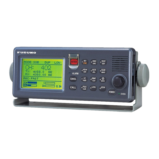
Furuno FS-1570 Installation Manual
150w/250w ssb radiotelephone
Hide thumbs
Also See for FS-1570:
- Service manual (322 pages) ,
- Operator's manual (222 pages) ,
- Installation manual (92 pages)
Table of Contents
Advertisement
FS-1570 (150 W)/FS-2570 (250 W)
SAFETY INSTRUCTIONS ......................................................................................................................i
SYSTEM CONFIGURATIONS ...............................................................................................................ii
EQUIPMENT LIST................................................................................................................................. iv
1. MOUNTING .................................................................................................................................... 1-1
1.1 Control Unit............................................................................................................................. 1-1
1.2 Antenna Coupler..................................................................................................................... 1-3
1.3 Transceiver Unit...................................................................................................................... 1-8
1.4 Handset (w/bracket) ............................................................................................................... 1-9
1.5 Antenna................................................................................................................................. 1-10
1.6 Mounting of Optional Equipment...........................................................................................1-11
2. WIRING .......................................................................................................................................... 2-1
2.1 Wiring...................................................................................................................................... 2-1
2.2 External Equipment ................................................................................................................ 2-5
2.3 Connection of AC-DC Power Supply Unit (option)................................................................. 2-9
2.4 Automatic Antenna Switch (option) ...................................................................................... 2-13
3. INITIAL SETTING........................................................................................................................... 3-1
3.1 Performance Check................................................................................................................ 3-1
3.2 Initializing Control Unit and Transceiver Unit ......................................................................... 3-1
3.3 Manual 2182 kHz Tuning Preset ............................................................................................ 3-3
3.4 System Setup ......................................................................................................................... 3-5
3.5 Setting DIP Switches .............................................................................................................. 3-9
3.6 Preamp Setting (For FAX-5)................................................................................................. 3-10
4. OPTION KIT ................................................................................................................................... 4-1
4.1 DSC Routine Frequency Board.............................................................................................. 4-1
4.2 Connecting of NBDP Terminal Unit OP05-96 (IB-581)/OP05-100 (IB-583) .......................... 4-3
PACKING LISTS.................................................................................................................................A-1
OUTLINE DRAWINGS .......................................................................................................................D-1
INTERCONNECTION DIAGRAM ......................................................................................................S-1
All brand and product names are trademarks, registered trademarks or service marks of their respective holders.
Installation Manual
SSB RADIOTELEPHONE
www.furuno.co.jp
Advertisement
Table of Contents

Related Manuals for Furuno FS-1570


Summary of Contents for Furuno FS-1570
-
Page 1: Table Of Contents
FS-1570 (150 W)/FS-2570 (250 W) SAFETY INSTRUCTIONS ...i SYSTEM CONFIGURATIONS ...ii EQUIPMENT LIST... iv 1. MOUNTING ... 1-1 1.1 Control Unit... 1-1 1.2 Antenna Coupler... 1-3 1.3 Transceiver Unit... 1-8 1.4 Handset (w/bracket) ... 1-9 1.5 Antenna... 1-10 1.6 Mounting of Optional Equipment...1-11 2. - Page 2 Nishinomiya, 662-8580, JAPAN Telephone : +81-(0)798-65-2111 : +81-(0)798-65-4200 All rights reserved. Printed in Japan Pub. No. IME-56360-J (HIMA ) FS-1570/2570 The paper used in this manual is elemental chlorine free. ・FURUNO Authorized Distributor/Dealer A : AUG J : OCT . 07, 2009...
-
Page 3: Safety Instructions
SAFETY INSTRUCTIONS DANGER Do not touch cable from the antenna coupler during transmission. Electrical shock, serious injury or death can result if the cables are touched during transmission. DANGER Do not touch this point. Do not touch the whip antenna or wire antenna. Electrical shock, serious injury or death can result if the antenna is touched during... -
Page 4: System Configurations
Standard configuration is shown with solid line. FS-1570 DSC DISTRESS SAFETY # = 2.6 m PREAMP UNIT whip FAX-5 antenna EPFS (GNSS) INCOMING INDICATOR IC-303-DSC MIF EQUIPMENT DISTRESS ALERT UNIT IC-302-DSC BK INTERFACE BK-300 ALARM UNIT IC-350 Exposed to weather... - Page 5 FS-2570 DSC DISTRESS SAFETY # = 2.6 m PREAMP UNIT whip FAX-5 antenna EPFS (GNSS) INCOMING INDICATOR IC-303-DSC MIF EQUIPMENT DISTRESS ALERT UNIT IC-302-DSC BK INTERFACE BK-300 ALARM UNIT IC-350 Unit Category Exposed to weather Preamp Unit Antenna Coupler Exposed to weather Protected from weather Other Units DSC ROUTINE...
- Page 6 05S0793 05S0793 RG-10/U-Y RG-10/U-Y RG-10/U-Y RG-10/U-Y RG-10/U-Y EQUIPMENT LISTS Code no. For FS-1570 (150 W) For FS-2570 (250 W) For FS-1570, Resin For FS-1570, Stainless steel For FS-2570, Resin For FS-2570, stainless steel 000-054-228 Handset, bracket, etc. 000-056-951 17JE23150-02 (D8C), 10 m cable...
-
Page 7: Optional Equipment
005-951-830 005-951-840 000-146-015 000-146-016 000-146-017 000-146-018 000-146-019 000-146-020 005-954-180 000-168-955-10 Remarks For FS-1570 (150 W) For FS-2570 (250 W) w/installation materials (CP16-01200), 1 set accessories (FP16-00100) 1 set w/Installation materials 1 set w/Installation materials 2.6 meter w/cable, 15 m 1 set... - Page 8 This page is intentionally left blank.
-
Page 9: Mounting
Do not apply paint, anti-corrosive sealant or contact spray to coating or plastic parts of the equipment. Those items contain organic solvents that can damage coating and plastic parts, especially plastic connectors. Control Unit 1.1.1 Mounting methods The control unit can be mounted one of four ways; •... -
Page 10: Flush Mounting
1.1.4 Flush Mounting Use the optional flush mount kit. Name: Flush mount kit Type: OP05-98 Code No.: 005-951-830 Name Type Mounting metal 05-089-1171 Wing bolt M4x30 Wing nut Hex. bolt M6x12 Spring washer 1. Make a cutout of 251 mm (W) x 100 mm (H). 2. -
Page 11: Antenna Coupler
Antenna Coupler ELECTRICAL SHOCK HAZARD Do not touch cable from the antenna coupler. Electric shock, fire, serious injury or death can result if the cables are touched during transmission. 1.2.1 Introduction The antenna coupler is installed between the antenna and the transceiver, and tunes the antenna to the transmitter. -
Page 12: Mounting Considerations
Grounding Run a copper strap (supplied) between the ground terminal of the antenna coupler and the ship’s superstructure. Solder 0.4 x 50 x 600 For outdoor installation, apply a coat of paint to prevent rust. 1.2.3 Mounting considerations The water-jetsproof construction of the antenna coupler permits installation either indoors or outdoors. - Page 13 Indoor installation Locate the unit away from GPS and radio equipment to avoid mutual interference. The lead-in wire should be as near to the unit as possible. Select a place where the unit can be easily maintained, but where it will not interfere with crew or passengers.
- Page 14 1.2.5 Mounting Fix the antenna coupler to a bulkhead of the bridge, mast, handrail, etc. For mounting on the mast, select a location within the total length of the antenna, and weld suitable mounting fixtures (local supply) to the mast and bolt the coupler there. For indoor installation, select a location where the distance between the lead-in insulator and the coupler is as short as possible.
- Page 15 Example for indoor installation insulator Lead-in insulator Stand-off insulator Stand-off Insulator For thin bulkhead, use nuts, bolts and washers U-bolt instead of tapping screws. assy. ANT SW BOX AS-1E (Option) From Antenna Switch Box EXAMPLE OF INDOOR MOUNTING Mounting the antenna coupler Mast Drain tube...
-
Page 16: Transceiver Unit
Select a location which provides adequate ventilation. The location must be clean and dry. The mounting location must be able to support the weight of the unit (FS-1570: 11.0 kg, FS-2570: 14.0 kg) under the continued conditions of vibration normally encountered aboard the vessel. -
Page 17: Handset (W/Bracket)
Handset (w/bracket) Unfasten six screws to remove the bracket cover, and fasten the bracket to the mounting location with two tapping screws 4 x 16 (supplied) on the desktop or bulkhead. Note: The magnet inside the bracket may pull the screwdriver when mounting the hanger. Handset hanger cover Screws... -
Page 18: Antenna
Locate the insulator away from funnels and masts. • If the antenna coupler is installed outdoors, use a lead-in insulator (Furuno type YA-150 for FS-1570 or YA-218 for FS-2570) to make the connection. If necessary, use a high quality antenna switch and stand-off insulator. •... -
Page 19: Mounting Of Optional Equipment
1.6 Mounting of Optional Equipment 1.6.1 AC-DC power supply unit Mounting considerations When selecting a mounting location, keep in mind the following points. • Select a location which provides adequate ventilation. • The location should be clean and dry. • The mounting location must be able to support the weight of the unit (PR-300:14.5 kg, PR-850A: 35 kg) under the continued conditions of vibration normally encountered aboard the vessel. - Page 20 1.6.3 Printer PP-510 Install the unit with the two mounting fixtures (supplied). Refer to the outline drawing at the end of this manual. Connect the interconnection cable between the printer and the transceiver unit. For how to load paper and set ribbon cassette, refer to the Operator’s Manual of the printer. Mounting 1.
- Page 21 1.6.4 Distress alert unit IC-302-DSC/Incoming indicator IC-303-DSC Select the mounting location where the button on the unit can be operated easily in an emergency. See the back of the manual for mounting dimensions and recommended clearance space. (Compass safe distance: Standard, 0.8 meters, Steering, 0.6 meters) 1.
- Page 22 1.6.6 Printer interface Referring to the outline drawing at the end of this manual, fix the printer interface with tapping screws (local supply) to tabletop or bulkhead. 1.6.7 Automatic Antenna Switch Install the automatic antenna switch between the SSB antenna and the antenna coupler. This unit allows you to connect the antenna to ground remotely when there is a possibility of lightning or the antenna must be grounded to comply with local regulations when returning to a harbor.
-
Page 23: Wiring
Coaxial cable AS-102 Local supply FS-1570T T/R ANT D.ANT(W/R 1) Wiring (FS-1570) FAX-5 Power status monitor PSM-01 PR-300 100V 10A 220V 5A DC OUT AC IN DC IN... - Page 24 To ANTENNA 1 ANT TUNE OK THROUGH TUNE DUMMY + 15V Ground drain wire. Ground Signal cable terminal Connect to ground to prevent interference and electrical shock. AS-102 to ship's ground AT-1560-25 (Resin type) TB-2 Replace this rubber sleeve with one supplied with accessories if using a coax cable whose diameter is larger than supplied one.
- Page 25 TB1 and 2. Fasten it to the fixing plate at cable entrance with a cable tie (local supply.) When connecting to the optional AC-DC power supply unit PR-300 (FS-1570) or 850A (FS-2570), supply AC power and DC power to the PR-300/850A. See paragraph “2.3 Connection of AC-DC Power Supply Unit”...
- Page 26 Note1: How to connect cable to the terminal board. 1. Press this downward by finger or screw driver. 2. Insert a core of cable. 3. Release the finger or screw driver. Control unit Connect the transceiver unit and the control unit by the supplied cable with D-sub 15 pin connector for both ends.
-
Page 27: External Equipment
Fabrication of 50 ohm coaxial cable 1 2 3 4 5 6 7 8 9 10111213141516 RCV BZ 05P0731 17181920 21222324 252627282930 3132 IEC61162 Distress alert unit 9 mm IC-302-DSC Incoming indicator IC-303-DSC CO-SPEVV-SB-0.2x5P TTYCS-4 T-IF Board (FS-1570) Connection of external equipment Solder here. - Page 28 IEC61162-1 (NMEA) equipment Connects a navigator to the terminal box in the transceiver unit. The FS-1570/2570 can receive the following sentences in IEC-61162-1 (ed.2nd) format. Use the interconnection cable type CO-SPEVV-SB-C 0.2x2P (option). GLL: Latitude and longitude RMC: Generic navigation information...
- Page 29 BK GND Tx_KEY Rx_MUTE SHIELD Note: When GND line from other radiotelephone is connected to the chassis, float the ground. External Battery FS-1570/2570 T-IF Board (05P0731) TB5 BK (+) 17 TX KEY BK GND Function Output voltage: 24 VDC Go to GND on transmitting.
- Page 30 FS-1570/2570 T-I/F Board (05P0731) TB5 BK(+) 17 TX KEY RX MUTE BK GND Example of connection with Tx/Rx unit MIF unit (future addition) Use 17JE-13250-02 connector (supplied as installation materials) to connect MIF unit to REMOTE port on transceiver unit.
-
Page 31: Connection Of Ac-Dc Power Supply Unit (Option)
When connecting to an AC and DC ship’s mains, the optional AC-DC power supply unit PR-300 (FS-1570) or PR-850A (FS-2570) is required. Attach the crimp-on lug FV5.5-S4 (local supply) to the power cable (local supply) for connection with the power supply unit. - Page 32 2.3.1 PR-300 for FS-1570 Both 100/110/200/220 VAC and 24 VDC are supplied to the AC-DC power supply unit PR-300. When AC input fails, DC power is supplied. Changing tap connections The transformer tap for input voltage has been set to 220 VAC (fuse 5A) at the factory.
- Page 33 2.3.2 PR-850A for FS-2570 Both 100/110/120/200/220/240 VAC and 24 VDC are supplied to the PR-850A. When AC input fails, DC power is directly supplied. For GMDSS vessels, 24 VDC power must be supplied through the radio battery. Wiring Connect cables to the input terminal on the front panel, using crimp-on lugs. Selection of input voltage The input voltage is adjustable for 100/110/120/200/220/240 VAC, and is factory-set for 220 VAC.
- Page 34 100VAC input White Black White Black 120VAC input White Black Black (Default setting) 220VAC input White White Black Black Ground Connect a ground wire between ship’s superstructure and a fixing hole on the PR-850A. 2-12 White Black White Black White White Black Selection of input voltage on PR-850A...
-
Page 35: Automatic Antenna Switch (Option)
Automatic Antenna Switch (option) Connect the SSB antenna to the ANT terminal, and use the antenna cable to connect the TRX terminal and the antenna coupler (ANT terminal) as shown below. For power, connect the DPYCY-1.5 cable (Japan Industrial Standard) between the following terminals on the transceiver unit and the automatic antenna switch;... - Page 36 DPYCY-1.5, fabrication Vinyl sheath Use crimp-on lugs, pre-attached to the terminal board in the Armor automatic antenna switch. RELAY board (location) Transceiver unit (FS-1570T) Transceiver unit (FS-2570T) 2-14 Solder a vinyl wire. Vinyl sheath Fix the cable with the cable gland at the vinyl sheath part.
-
Page 37: Initial Setting
Initializing Control Unit and Transceiver Unit The control unit is commonly used with the transceiver unit of FS-1570, FS-2570 and FS-5070. Therefore, initialize the units at installation as follows. 1. Turn on the power switch on the control unit. A while later, the radiotelephone (RT) screen appears. - Page 38 MMSI SET MMSI CLEAR ALL CLEAR 3. Enter the password referring to appropriate FURUNO INFORMATION. Regulations prohibit the release of the password to users. 4. Rotate the ENTER knob to select MMSI SET and press the ENTER knob. 5. Enter MMSI (Own ship’s ID).
-
Page 39: Manual 2182 Khz Tuning Preset
3.3 Manual 2182 kHz Tuning Preset For safety measure, it is required that 2182 kHz be tunable both automatically and manually. The setup to enable manual tuning, in the event the antenna tuner system fails, is made with the DIP switches in the antenna coupler. Call a coast station and tell your situation. Be sure not to transmit during silent period (00 to 03 min. - Page 40 4. Press the [LOG/TUNE] key. “TUNE” appears on the LCD. “TUNING: OK” appears when tuning is completed. Record the status (on or off) of LEDs CR1 – CR22 (on the COUPLER Board). 5. Set S1 switch to MANUAL. 6. Set S4, S5, S6 DIP switches so that LEDs become the status is the same as in step 4. The relations between the DIP switch and LED are shown on the next page.
-
Page 41: System Setup
1. Press the [SETUP] key to display the Setup menu. 2. Rotate the [ENTER] knob to select “SYS SETUP”. 3. Enter the password referring to appropriate FURUNO INFORMATION to display the System setup menu. The password cannot be informed customers by statute. - Page 42 SIG DET S LEVEL SIG DET S LEVEL judges whether the DSC frequency to use to send a DSC message is in use or not. The DSC message is not transmitted when the signal strength on the DSC frequency is higher than that set here. When the DSC frequency becomes clear, the DSC message is automatically transmitted.
- Page 43 3.4.3 RT System setup Choose “RT SYSTEM SETUP” on the System setup menu, and then press the [ENTER] knob to show the RT ‘Radio Telephone) System setup menu. RT System setup REGULATION : INTL TX FREQ AM ENABLE LSB ENABLE : OFF...
- Page 44 3.4.4 System setting of RT Set the RT similarly with DSC. Do the setting at System setup menu at the transceiver unit. Item REGULATION Select the national regulation to change the frequency, user channel, etc. TX FREQ Select the frequency to transmit. FREE: Any frequency can be set.
-
Page 45: Setting Dip Switches
Setting DIP Switches Location of DIP Switches IEC (NMEA)/MIF data receiving line (S2) IEC (NMEA) RS-422 S2-#1 RS-422 S2-#3 S3-#1, 2 S3-#3, 4 Note: S2-#4 is no used. IC-302-DSC Set to Current Loop for IC-302 connection. CPU Board (05P0732) Current Loop Bold: default setting RS-422/232C Current Loop... -
Page 46: Preamp Setting (For Fax-5)
Preamp Setting (For FAX-5) When using the preamp for the watch receiver antenna, set J3 on the W/R Board to ACTIVE in the transceiver unit. ACTIVE Change jumper to ACTIVE position. W/R Board, 05P0734 3-10... -
Page 47: Option Kit
4. OPTION KIT DSC Routine Frequency Board For FS-2570, the W/R Board 05P0734A (option) enables reception of DSC routine frequencies without the SSB radiotelephone connection. For complete modification, the whip antenna for DSC routine frequency is necessary. • Necessary Parts :W/R2 Board Kit, Type Name W/R Board... - Page 48 How to use SSB antenna coupler for DSC routine frequency receive To use the SSB antenna coupler for routine watch keeping, the following modification is necessary. Note: When transmitting, DSC routine frequency cannot be received. 1. Open the transceiver unit. 2.
-
Page 49: Connecting Of Nbdp Terminal Unit Op05-96 (Ib-581)/Op05-100 (Ib-583)
4.2 Connecting of NBDP Terminal Unit OP05-96 (IB-581)/OP05-100 (IB-583) To use this equipment for the telex, the NBDP terminal unit is required. Name: NBDP terminal set, Type: OP05-96, Code No.: 000-056-949 Name Type Terminal unit IB-581-02 DSP Board OP05-97 Name: NBDP terminal set, Type: OP05-100, Code No.: 000-056-956 Name Type Terminal unit... - Page 50 Mounting the IB-581 Refer to the outline drawing at the back of this manual. 1. Fix the hanger by using five tapping screws (supplied with option kit). 2. Attach all connectors to the bottom of the terminal unit. Communication unit 3.
- Page 51 Mounting the IB-583 1. Fix the hanger by using four tapping screws (supplied with option kit). 4- 7 2. Tighten two knobs to the terminal unit loosely. 3. Mount the terminal unit to the hanger, and then fasten knobs. 4. Attach the earth wire 08S0087 to the earth terminal at the back of the terminal unit. 5.
- Page 52 This page is intentionally left blank.
- Page 64 21/Aug/08 R.Esumi...
- Page 67 D-10...
- Page 68 D-11 26/Jun/09 R.Esumi...
- Page 69 D-12...
- Page 70 D-13...
- Page 71 D-14...
- Page 72 D-15...
- Page 73 D-16 T.Matsuguchi Sep.21'06...
- Page 75 D-18...
- Page 76 D-19...
- Page 77 D-20...
- Page 78 D-21 25/Sep/08 R.Esumi...
- Page 79 D-22 25/Sep/09 R.Esumi...
-
Page 81: Interconnection Diagram
IN-C TD4-B ALARM UNIT OUT-H RD4-A IC-350 RD4-B OUT-C DIST_CTR CTO-C 0V(GND) TITLE FS-1570 T.YAMASAKI 名称 SSB送受信機 T.TAKENO 相互結線図 25/Sep/09 R.Esumi MASS NAME SSB RADIOTELEPHONE INTERCONNECTION DIAGRAM C5636-C01- L FURUNO ELECTRIC CO., LTD. TTYCS-4 着信指示器 MAX.50m DISTRESS/URGENT RECEIVING UNIT IC-303-DSC... - Page 82 IN-C TD4-B ALARM UNIT RD4-A OUT-H IC-350 RD4-B OUT-C DIST_CTR CTO-C 0V(GND) TITLE FS-2570 T.YAMASAKI 名称 SSB送受信機 T.TAKENO 相互結線図 25/Sep/09 R.Esumi MASS NAME SSB RADIOTELEPHONE INTERCONNECTION DIAGRAM C5637-C01- L FURUNO ELECTRIC CO., LTD. TTYCS-4 着信指示器 MAX.50m DISTRESS/URGENT RECEIVING UNIT IC-303-DSC...