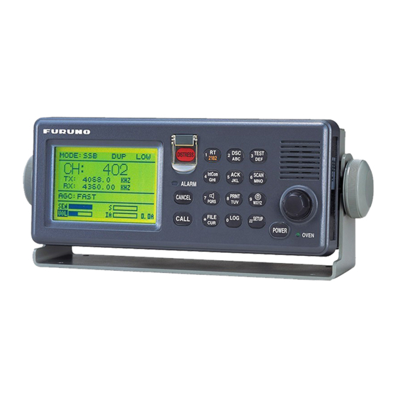
Furuno FS-1570 Operator's Manual
150w/250w ssb radiotelephone
Hide thumbs
Also See for FS-1570:
- Service manual (322 pages) ,
- Operator's manual (215 pages) ,
- Installation manual (92 pages)
Table of Contents
Advertisement
Quick Links
Advertisement
Table of Contents
Troubleshooting

Related Manuals for Furuno FS-1570


Summary of Contents for Furuno FS-1570
-
Page 1: Ssb Radiotelephone
SSB RADIOTELEPHONE FS-1570 (150 W) FS-2570 (250 W) - Page 2 Printed in Japan All rights reserved. All rights reserved. Pub. No. OME-56360 Pub. No. OME-56360 ( ( YOSH YOSH ) ) FS-1570/2570 FS-1570/2570 The paper used in this manual is elemental chlorine free. FURUNO Authorized Distributor/Dealer FURUNO Authorized Distributor/Dealer FIRST EDITION : FIRST EDITION : OCT.
- Page 3 Distress Alert Calling Procedure Below is the procedure for transmitting a distress alert via radiotelephone. Transmit the distress alert when a life-endangering situation occurs on your vessel. 1. Open the DISTRESS button cover and press the [DISTRESS] button more than three seconds to show the following display, then release the [DISTRESS] button.
- Page 4 Antenna equipment or something is dropped in Wire the equipment. Continued use of the equipment can cause Lead-in fire or electrical shock. Contact a FURUNO Insulator agent for service. (High Voltage) Do not disassemble or modify the equipment.
- Page 5 A warning label is attached to the transceiver unit and a danger label is attached to the antenna coupler. Do not remove the labels. If a label is missing or illegible, contact a FURUNO agent or dealer about replacement. Name: Warning Label (1) WARNING Type: 86-003-1011-1 To avoid electrical shock, do not Code No.: 100-236-231...
-
Page 6: Table Of Contents
TABLE OF CONTENTS FOREWORD ... ix SYSTEM CONFIGURATION... xi SPECIFICATIONS... SP-1 1 OPERATIONAL OVERVIEW... 1-1 1.1 Controls... 1-1 1.2 Turning the Power On/Off ... 1-2 1.3 Panel Dimmer, LCD Contrast... 1-2 1.4 Indications ... 1-3 1.4.1 DSC standby screen... 1-3 1.4.2 Radiotelephone screen... - Page 7 2.6 User Channels ... 2-10 2.6.1 Registering user channels... 2-10 2.6.2 Deleting user channels... 2-12 2.7 FAX Enable/Disable ... 2-12 2.8 Speaker Setting in Off Hook ... 2-13 3 DSC OVERVIEW ... 3-1 3.1 What is DSC? ... 3-1 3.2 DSC Call ... 3-1 3.2.1 Distress alert call and reply ...
- Page 8 5.7 Polling Call ... 5-28 5.7.1 Sending a polling call... 5-28 5.7.2 Receiving a polling call ... 5-31 5.8 Position Call ... 5-33 5.8.1 Position call: requesting other ship’s position... 5-34 5.8.2 Position call: other ship requests your position ... 5-36 5.9 PSTN Call...
- Page 9 9 NBDP PREPARATIONS... 9-1 9.1 Registering Answerback Code & ID Codes ... 9-1 9.1.1 Registering answerback code ... 9-1 9.1.2 Registering ID codes... 9-2 9.2 Station List ... 9-2 9.2.1 Registering stations... 9-3 9.2.2 Editing/Deleting stations... 9-4 9.3 Timer Programming... 9-5 9.3.1 Registering timer programs...
- Page 10 11.6 Timer Operation ...11-8 11.6.1 Enabling timer operation ...11-8 11.6.2 Stopping timer operation ...11-9 11.7 Scanning...11-9 11.8 Communication Buffer...11-10 11.9 Preparing Macrofiles for Automatic Telex ...11-10 11.9.1 Automatic telex overview ...11-10 11.9.2 Preparations ... 11-11 11.9.3 Commands ...11-12 11.9.4 Store-and-forward method ...11-13 DIRTLX macrofile ...11-15 11.10 Automatic Telex using Macrofile ...11-17 12 MAINTENANCE &...
-
Page 11: Foreword
FOREWORD Thank you for purchasing the FS-1570 (150 W)/FS-2570 (250 W) SSB Radiotelephone. We are confident you will discover why FURUNO has become synonymous with quality and reliability. Dedicated in the design and manufacture of marine electronics equipment for over half a century, FURUNO Electric Company has gained an unrivaled reputation as a world leader in the industry. - Page 12 DSC/watch receiver Distress, safety and routine calling Scanning of DSC frequencies for distress and general calls on MF/HF File editing capability for readiness in case of emergency PSTN (Public Switched Telephone Network) capability standard Log stores 50 each of latest ordinary, distress and transmitted messages, in separate memory blocks.
-
Page 13: System Configuration
SYSTEM CONFIGURATION FS-2570 (250 W) PREAMP PREAMP FAX-5 FAX-5 NAVIGATOR INCOMING INDICATOR IC-303-DSC TELEX DISTRESS ALERT BUTTON IC-302-DSC DISTRESS MESSAGE CONTROLLER DMC-5 * = For distress watch keeping receiver ** = For DSC general frequency watch keeping receiver Antenna Coupler AT-1560-25 LOUDSPEAKER SEM-21Q... - Page 14 FS-1570 (150 W) PREAMP FAX-5 NAVIGATOR INCOMING INDICATOR IC-303-DSC TELEX DISTRESS ALERT BUTTON IC-302-DSC DISTRESS MESSAGE CONTROLLER DMC-5 # = For distress watch keeping receiver Antenna Coupler AT-1560-25 LOUDSPEAKER SEM-21Q CONTROL UNIT FS-2570C TRANSCEIVER UNIT FS-1570T NBDP TERMINAL UNIT IB-581/IB-583...
-
Page 15: Specifications
8 tones 64 steps 1 minute approx. (oven 20 minutes approx.) 1,606.5 kHz to 26.175 MHz (100 Hz steps) FS-1570: 150 Wpep, FS-2570: 250 Wpep Within ±10 Hz Low power balanced modulation -46 dBm/600 ohms (Handset/Microphone) -10 dBm/600 ohms (Handset HS-2001) - Page 16 1.10 Audio Output Power 1.11 Standard Features DSC/WATCH KEEPING RECEIVER DIGITAL SELECTIVE CALLING 2.1.1 Frequency Shift 2.1.2 Baud Rate 2.1.3 Protocol 2.1.4 Modulation 2.1.5 Distress Alarm 2.1.6 Distress Alarm Memory DSC/WATCH RECEIVER 2.2.1 Frequency Range MF/HF specification MF specification 2.2.2 Class of Emission 2.2.3 Antenna Impedance...
- Page 17 2.3.8 Receiving System 2.3.9 Radiation 2.3.10 RX Error Rate 2.3.11 Spurious Response 2.3.12 Scanning Reception 2.3.13 Diagnosis NBDP FUNCTION (OPTION) GENERAL 3.1.1 Communication Mode 3.1.2 Protocol ID code Line cord Modulation Tone frequency Tracking range 3.1.3 Applications Auto-reception Frequency scanning User-channels TERMINAL UNIT IB-583...
- Page 18 Antenna Coupler 150 W (FS-1570), 250 W (FS-2570) 1.5 max Within 15 s FS-1570: 10 ohms + 250 pF/100W mounted in coupler FS-2570: 10 ohms + 250 pF/200W mounted in coupler IEC 61162-1 (NMEA 0183-3) GGA>RMC>GLL 24 VDC: 0.8 A, max. 20 A (TX) 24 VDC: 1.5 A, max.
-
Page 19: Operational Overview
OPERATIONAL OVERVIEW 1.1 Controls FURUNO Control POWER switch Turns the power on/off. DISTRESS Press and hold down the button more than three seconds to transmit the button distress alert. CALL key Transmits calls. ENTER knob Radiotelephone: Rotate to change TX/RX channel, sensitivity, audio volume, etc.;... -
Page 20: Turning The Power On/Off
1 OPERATIONAL OVERVIEW Turns loudspeaker on/off. (Note that this key does not silence the distress or urgency alarm.) 8/PRINT key Prints communications log files, current screen (except DSC standby screen and radiotelephone screen) and test results. Adjusts panel dimmer and LCD contrast. FILE/CURSOR Opens the send message file list from the DSC standby screen, to send stored message. -
Page 21: Indications
1.4 Indications 1.4.1 DSC standby screen The DSC standby screen may be displayed by pressing the [6/SCAN] key. WATCH KEEPING DISTRESS 2187.5 4207.5 16804.5 12577.0 ROUTINE 2177.0 4219.5 16903.0 12657.0 35 00.000N 135 00.000E 23:59 Position and time. "MANUAL" shown when these are input manually. -
Page 22: Loudspeaker
1 OPERATIONAL OVERVIEW 1.5 Loudspeaker 1. Press the [7/ ] key to alternately disable or enable the loudspeaker and the alarm generated for routine messages. SOUND: ON or SOUND: OFF appears with each press. 2. To adjust loudspeaker volume do the following: The method of adjustment depends on the setting of “VOLUME INPUT”... -
Page 23: Automatic Acknowledge On/Off
1.7 Automatic Acknowledge On/Off The automatic acknowledge feature of the DSC/watch receiver automatically transmits the acknowledge back (ACK BQ) signal to the sending station when an individual, position or polling call is received. (For position and polling calls, respective item on the AUTO ACK menu must be turned on to enable automatic acknowledge.) Automatic acknowledge can be turned on or off at the DSC standby screen by the [5/ ACK/SQ] key. - Page 24 1 OPERATIONAL OVERVIEW 3. Push the [ENTER] knob to open the INPUT TYPE menu. Position setup INPUT TYPE: AUTO AUTO LAT : 34 41 NORTH MANUAL LON : 135 30 EAST TIME: 09: 00 UTC Note 1: If, when INPUT TYPE is AUTO, input from the navigator is interrupted, the message “EPFS error!”...
-
Page 25: System Characteristics
1.9 System Characteristics 1.9.1 Equipment priority Equipment priority order is as below. 1. DMC 2. Control unit sending distress alert 3. Control unit 1 – routine use 4. Control unit 2 – routine use 5. NBDP 1.9.2 Controls become inoperative Controls become inoperative in the following conditions: Controls of idle control unit in the two-control unit system when other control unit goes OFF HOOK. -
Page 26: Power Supply Unit (Option)
(115 or 230 VAC). The power supply unit is type PR-300, supplying 24 VDC power (20 A) to the FS-1570 or type PR-850A, supplying 24 VDC (40 A) to the FS-2570. Both 115/230 VAC and 24 VDC power can be connected simultaneously. In this case, the system normally operates on the AC mains supply and when AC power is lost, the PSU automatically switches to the DC power source. -
Page 27: Ssb Radiotelephone
SSB RADIOTELEPHONE You can enter desired frequency by channel or TX and RX frequencies. The handset may be ON HOOK or OFF HOOK. To set the SSB radiotelephone to 2182 kHz/J3E automatically, press the [1/ RT/2182] key more than two seconds. 2.1 Transmitting After selecting class of emission and frequency, you can transmit by pressing the PTT switch on the handset. -
Page 28: Choosing Channel, Frequency
2 SSB RADIOTELEPHONE 2.1.2 Choosing channel, frequency Choosing channel 1. Rotate the [ENTER] knob to choose CH and then push the [ENTER] knob. MODE: SSB SIMP CH: 800 TX: 2182.0 RX: 2182.00 AGC : FAST 2. Channel can be entered directly with the numeric keys, or by using the [ENTER] knob. See below for details. -
Page 29: Tuning
Choosing frequency 1. Rotate the [ENTER] knob to choose TX or RX as appropriate and then push the [ENTER] knob. SIMP HIGH CH: 200 TX: 2182.0 123456.78 AGC : SLOW 2. Enter frequency by one of the methods below. Entering frequency with the numeric keys: Use the numeric keys to enter frequency and then push the [ENTER] knob. -
Page 30: Using The Handset
2 SSB RADIOTELEPHONE Note: When tuning is initiated in the two-control unit system, the display of the idle control unit shows “OCCUPIED(ANOTHER CONTROLLER).” In this case, only the DISTRESS button is operative on the idle control unit. Further, if a control unit is in use when tuning is attempted at the other control unit, the display of the control unit which attempted to tune shows “OCCUPIED”... -
Page 31: Reducing Transmitter Power
2. Push the [ENTER] knob. MODE: SSB SIMP CH: 200 TX: 2182.0 RX: 2182.00 AGC : FAST 3. Rotate the [ENTER] knob to choose option desired and then push the [ENTER] knob. FS-1570 HIGH 68 W 100 W HIGH 150 W 2.1A HIGH 2.1A... -
Page 32: Receiving
2 SSB RADIOTELEPHONE 2.2 Receiving 2.2.1 RF gain (sensitivity) adjustment In normal use the sensitivity should be set for maximum. If the audio on the received channel is unclear or interfered with other signals, adjust (usually reduce) sensitivity to improve clarity. 1. -
Page 33: Squelch Control, Squelch Frequency
MODE: AM SIMP CH: 200 TX: 2182.0 2182.00 KHZ 123456.78 AGC : SLOW 5. Key in RX frequency with the numeric keys and then push the [ENTER] knob. 2.2.5 Squelch control, squelch frequency Squelch on/off The squelch mutes the audio output in the absence of an incoming signal. Press the [5/ ACK/SQ key] to turn on and off the squelch alternately. -
Page 34: Intercom
2 SSB RADIOTELEPHONE 2.3 Intercom The built-in intercom permits voice communications between two FS-2570C Control Units. 1. Press the [1/ RT/2182] key to show the radiotelephone screen. 2. Off hook the handset. 3. Press the [4/IntCom] key to show INTERCOM on the display. The called party’s handset rings. -
Page 35: When Automatic Tuning Fails
2.5 When Automatic Tuning Fails The antenna coupler automatically tunes a wire or whip antenna to the transceiver. When all frequencies cannot be tuned, TUNE OK will not appear on the display. In this case, you can tune 2182 kHz by manually operating the coupler as shown in the procedure below. DANGER HIGH TENSION HAZARD DO NOT TRANSMIT WHEN... -
Page 36: User Channels
2 SSB RADIOTELEPHONE 2.6 User Channels The USER CH menu allows registration of user TX and RX channels, where permitted by the Authorities. FURUNO will assume no responsibility for the disturbance caused by the unlawful or improper setting of user channels. - Page 37 5. Rotate the [ENTER] knob to choose MODE and then push the [ENTER] knob. User ch entry " MODE: 00201. TX: 2111.5 RX: 2111.5 NBDP 00202. TX: 2222.0 RX: 2222.0 00203. TX: 2333.5 RX: 2333.5 00204. TX: 2444.0 RX: 2444.0 00205.
-
Page 38: Deleting User Channels
2 SSB RADIOTELEPHONE 2.6.2 Deleting user channels Deleting individual user channels 1. At the radiotelephone screen, press the [#/SETUP] key. 2. Rotate the [ENTER] knob to choose USER CH and then push the [ENTER] knob. 3. Rotate the [ENTER] knob to choose ENTRY and then push the [ENTER] knob. 4. -
Page 39: Speaker Setting In Off Hook
2.8 Speaker Setting in Off Hook When the handset is off hook, you may choose to turn the speaker (panel speaker or external speaker) on or off. The default setting is OFF which turns off the speaker when the handset is off hook. The ON position keeps the speaker on always, regardless of handset state. - Page 40 2 SSB RADIOTELEPHONE (This page intentionally left blank.) 2-14...
-
Page 41: Dsc Overview
DSC OVERVIEW 3.1 What is DSC? DSC is an acronym meaning Digital Selective Calling. It is a digital distress and general calling system in the MF and HF bands used by ships for transmitting distress alerts and general calls and by coast stations for transmitting the associated acknowledgements. For DSC distress and safety calling in the MF and HF bands, the frequencies are (kHz) 2187.5, 4207.5, 6312.0, 8414.5, 12577.0, and 16804.5. - Page 42 DSC OVERVIEW Contents of a DSC call Calling category Call category Individual Individual, PSTN, Test, Position, Polling, Relay Sel (specific coast station) All Ships All Ships, Neutral, Medical, Relay All Group Group Geographical Area Area Distress Call Distress Station ID Own ship ID and sending station ID.
-
Page 43: Distress Alert Call And Reply
3.2.1 Distress alert call and reply This type of call is sent by own ship in the event of distress, by using the [DISTRESS] button as follows: 1. The LED in the [DISTRESS] button initially flashes, and lights when the button is pressed more than three seconds. -
Page 44: Individual Call
DSC OVERVIEW 3.2.2 Individual call The individual call is for sending a call to a specific station. Own Ship Basic procedure (radiotelephone) 1. Prepare call and transmit it by pressing the [CALL] key. The equipment then awaits acknowledgement of the call. 2. -
Page 45: Interpreting Call Displays
3.4 Interpreting Call Displays This paragraph provides the information necessary for interpreting receive and send call displays. 3.4.1 Receive calls Below are sample distress and individual receive calls. The content of other types of receive calls is similar to that of the individual call. When you receive a call, the message “INCOMING”... - Page 46 DSC OVERVIEW Individual receive call Received message MAR-23-2002-23:59 ECC: OK INDIVIDUAL REQUEST FROM SHIP: 123456789 ROUTINE TX: 2182.0 KHZ TELEPHONE RX: 2182.0 KHZ " ANSWER ALL VIEW Push [ENTER] knob to switch. Received message WORKING FREQ. : TX: 2182.0 KHZ 2182.0 END OF SEQUENCE: ACK.
-
Page 47: Send Calls
3.4.2 Send calls Below are sample distress and individual send calls. The content of other types of send calls is similar to that of the individual call. Distress send call Distress call in progress! NATURE: UNDESIGNATED POS: 12 34N 123 45E AT 12:34 TELEPHONE 2182.0 KHZ DSC FREQ... - Page 48 DSC OVERVIEW (This page intentionally left blank.)
-
Page 49: Distress Operations
DISTRESS OPERATIONS 4.1 Sending Distress Alert GMDSS ships carry a DSC terminal with which to transmit the distress alert in the event of a life-endangering situation. A coast station receives the distress alert and sends the distress alert acknowledge call to the ship in distress. Then, voice or telex communications between the ship in distress and coast station begins. - Page 50 4 DISTRESS OPERATIONS 2. The display changes as below. It takes about 40 seconds to transmit the distress alert, and the number of seconds until transmission is completed is shown at the bottom of the display. At this time the output power of the radiotelephone is automatically set to maximum.
-
Page 51: Sending Distress Alert By Distress Button, Nature Of Distress Specified
Received message JAN-23-2002-23:59 ECC: OK DISTRESS ACKNOWLEDGE FROM COAST: 001234567 SHIP IN DIST: 123456789 NATURE: UNDESIGNATED POS: 12 34N 123 45E AT 12:34 TELEPHONE 2182.0 KHZ GO TO ALL VIEW 6. Communicate with the coast station via radiotelephone, following the instructions below. - Page 52 4 DISTRESS OPERATIONS 4. Push the [ENTER] knob to open the INPUT TYPE menu. INPUT TYPE: AUTO AUTO LAT : 34 41 NORTH MANUAL LON : 135 30 EAST NO INFO TIME: 09: 00 UTC 5. Rotate the [ENTER] knob to choose MANUAL and then push the [ENTER] knob. If you cannot confirm your position, choose NO INFO, push the [ENTER] knob and then go to step 10.
- Page 53 10. The COMPOSE MESSAGE screen is redisplayed. Push the [ENTER] knob to open the COM. TYPE menu. Compose message DISTRESS CALL TYPE: NATURE: FLOODING TELEPHONE POS: 35 N 135˚00E AT 23:25 NBDP-FEC COM. TYPE: TELEPHONE DSC FREQ : 2187.5 KHZ GO TO ALL VIEW 11.
-
Page 54: Receiving A Distress Alert
Station List ABC-6M ABC-12M ABC-8M FURUNO 4. “DSC” is selected; press the [Enter] key to connect the communications line. 5. “Connect” appears in reverse video. Type and transmit your message, giving the following information: a) Ship’s name and call sign... -
Page 55: Distress Alert Received On Mf Band
4.2.1 Distress alert received on MF band Do the following: Continue watching on 2182 kHz. Wait for coast station to acknowledge the distress call. Watch until “SEELONCE FINI” is announced. If multiple DSC distress alerts are received from the same ship in distress and it is beyond a doubt in your vicinity, a DSC acknowledgement may, after consultation with an RCC or Coast Station, be sent to terminate the call by DSC. - Page 56 4 DISTRESS OPERATIONS Sending the distress acknowledge call to ship in distress (on MF band) Transmit the distress acknowledge call to the ship in distress only when you do not receive it from a coast station and you are able to aid the ship in distress. First, transmit the distress acknowledge to the ship in distress by telephone.
-
Page 57: Distress Alert Received On Hf Band
6. Press the [CALL] key, and the message “Category distress transmit sure?” appears. Continue press the key until the message “Distress acknowledge call in progress appears, to transmit the distress acknowledge call to the ship in distress. 4.2.2 Distress alert received on HF band If you receive a distress alert on the HF band, the ALARM lamp lights and the audio alarm sounds. - Page 58 4 DISTRESS OPERATIONS Action for ships receiving distress alert on HF band DSC Distress alert received. Press [CANCEL] key to silence alarm. Listen to associated RTF or NBDP channel(s) for 5 minutes. Is the alert acknowledged or relayed by CS and or RCC? CS = Coast Station RCC = Rescue Co-ordination Center...
- Page 59 4. Push the [ENTER] knob to open the CALL TYPE menu. Compose message CALL TYPE* INDVIDUAL RELAY ALL DISTRESS RELAY RELAY COAST ID IN DIST: 987654321 DSC FREQ 8414.5 KHZ GO TO ALL VIEW 5. If you know the ID of the nearest coast station, choose RELAY COAST and then push the [ENTER] knob.
- Page 60 4 DISTRESS OPERATIONS Note: If a coast station acknowledges the call before the timer counts down to zero, press the [CANCEL] key to cancel the distress relay call. 10. After the call is transmitted, the message “Wait for distress relay acknowledge.” appears.
-
Page 61: Sending Distress Relay On Behalf Of A Ship In Distress
4.3 Sending Distress Relay on Behalf of a Ship in Distress 4.3.1 Sending distress relay to coast station You may send the distress relay to a coast station on behalf of a ship in distress in the following cases: You are near the ship in distress and the ship in distress cannot transmit the distress alert. - Page 62 4 DISTRESS OPERATIONS 7. Push the [ENTER] knob to open the NATURE menu. Compose message CALL TYPE : All ships UNDESIGNATED COAST ID FIRE ID IN DIST FLOODING : 987654321 COLLISION NATURE :Undesignated GROUNDING POS: ION. LISTING COM.TYPE DSC FREQ 8.
- Page 63 12. Rotate the [ENTER] knob to choose TELEPHONE and then push the [ENTER] knob. (NBDP-FEC may also be used.) Push the [ENTER] knob to open the DSC FREQ menu. Compose message CALL TYPE: RELAY ALL DISTRE 123456789 4207.5 COAST ID: 6312.0 ID IN DIST: 12577.0...
-
Page 64: Sending Distress Relay To All Ships
4 DISTRESS OPERATIONS 16. When you receive the distress relay acknowledge call, the audio alarm sounds and the display shown below appears. Distress relay ack call received. COAST ID : 001234567 SHIP IN DIST : NO INFO NATURE : SINKING POS : 12 34N 123 45E AT 12:34 TELEPHONE... - Page 65 5. Push the [ENTER] knob to open the NATURE menu. Compose message CALL TYPE : All ships UNDESIGNATED FIRE ID IN DIST FLOODING : 987654321 NATURE COLLISION :Undesignated POS: ION. GROUNDING COM.TYPE LISTING DSC FREQ 6. Rotate the [ENTER] knob to choose nature of distress and then push the [ENTER] knob.
- Page 66 4 DISTRESS OPERATIONS 11. Push the [ENTER] knob to open the DSC FREQ menu. Compose message CALL TYPE: RELAY ALL ID IN DIST: 123456789 4207.5 NATURE: UN 6312.0 POS: 34 45N COM TYPE: 12577.0 16804.5 DSC FREQ GO TO EASY VIEW GO TO ALL VIEW 12.
-
Page 67: Receiving Distress Relay All Ships
4.4 Receiving Distress Relay All Ships When you receive a distress relay for all ships, continue monitoring distress and safety frequencies. 1. The audio alarm sounds and the display looks like the one below when a distress relay all ships call is received. Distress relay all call received. - Page 68 4 DISTRESS OPERATIONS (This page intentionally left blank.) 4-20...
-
Page 69: Calling, Receiving
CALLING, RECEIVING This chapter provides the information necessary for general calling and receiving. 5.1 All Ships Call When an urgent but not life-endangering situation arises on your ship, for example, engine trouble, send an all ships call to request assistance. After sending the call, you can communicate by voice over the radiotelephone, or send a message by telex. - Page 70 5 CALLING, RECEIVING 3. Push the [ENTER] knob to display the PRIORITY menu. Compose message CALL TYPE: ALL SHIPS SAFETY PRIORITY URGENCY COM. TYPE : TELEPHONE DISTRESS DSC FREQ 2187.5 KHZ GO TO ALL VIEW 4. Rotate the [ENTER] knob to choose SAFETY or URGENCY as appropriate and then push the [ENTER] knob.
-
Page 71: Receiving An All Ships Call
Sending message by NBDP Terminal Unit 1. The message “STATION ENTRY COMPLETED FROM DSC. Press any key to escape.” appears on the NBDP’s display. Press any key on the NBDP Terminal Unit to erase the message. 2. Press the function key [F3] on the keyboard of the NBDP Terminal Unit to show the Operate menu. -
Page 72: Individual Call
5 CALLING, RECEIVING 5.2 Individual Call The individual call is for calling a specific station. After sending an individual call, called ACK RQ transmission, wait to receive the acknowledge back (ACK BQ) signal from the receiving station. 5.2.1 Sending an individual call 1. - Page 73 6. Rotate the [ENTER] knob to choose appropriate priority (normally ROUTINE) and then push the [ENTER] knob. 7. Push the [ENTER] knob to open the COM. TYPE menu. Compose message : INDIVIDUAL CALL TYPE : --------- STATION ID TELEPHONE : ROUTINE PRIORITY NBDP-ARQ COM.
- Page 74 5 CALLING, RECEIVING Routine or ship's business priority Safety or urgency priority 11. Follow the instructions on the next page to choose DSC frequency desired.
- Page 75 Compose message CALL TYPE: INDIV 2 MHZ 4 MHZ STATION ID: 123456 6 MHZ PRIORITY: 8 MHZ COM. TYP: TELEP 12 MHZ COM. FREQ: NO I DSC FREQ : 2M-INTL GO TO ALL VIEW Rotate the [ENTER] knob Compose message to scroll menu to view user CALL TYPE : Individual...
- Page 76 5 CALLING, RECEIVING 12. Press the [CALL] key to send the individual call (transmission time: about seven seconds). The display shows the message "Individual request call in progress!" while the call is being sent. Individual request call in progress! TO SHIP: 123456789 ROUTINE TELEPHONE...
- Page 77 Able acknowledge call received Communicating by radiotelephone The audio alarm sounds; press the [CANCEL] key to silence it, and the display changes as below. Press the [CANCEL] key to go to the radiotelephone screen. The working frequency is automatically set; you may start voice communications by radiotelephone. Received message MAR-23-2002-23:59 ECC: OK...
-
Page 78: Receiving An Individual Call
5 CALLING, RECEIVING 5.2.2 Receiving an individual call When own ship receives an individual call, acknowledgement is automatically or manually sent depending on the comply-type setting (see paragraph 7.2). The relationship between comply type and automatic/manual acknowledge is as shown in the table below. Comply type Setting of [5/ACQ /SQ] key... - Page 79 Communicating by NBDP Terminal Unit After acknowledging an individual call, do the following to send a message by NBDP Terminal Unit. 1. The control unit’s display shows “OCCUPIED” and the TX and RX frequencies. 2. The message from the other station appears on your NBDP Terminal Unit. 3.
- Page 80 5 CALLING, RECEIVING 5. If you want to send a proposal, rotate the [ENTER] knob to choose RE-SEND and then push the [ENTER] knob. Compose message CALL TYPE : UNABLE ACKNOWLEDGEMENT STATION ID : 001234567 REASON: NO REASON GIVEN STATION ID: 001234567 DSC FREQ : 12M-INTL GO TO ALL VIEW...
- Page 81 4. Rotate the [ENTER] knob to choose ABLE and then push the [ENTER] knob. The display changes as below. (Working frequency is automatically set as specified by other party.) Compose message CALL TYPE: ABLE ACKNOWLEDGEMENT STATION ID: 121234567 COM. TYPE: TELEPHONE COM.
- Page 82 5 CALLING, RECEIVING Manually acknowledging individual call with “UNABLE” 1. When an individual call is received and the equipment is set up with manual acknowledge, the alarm sounds and the display shows the message "Individual request call received." Individual request call received.
-
Page 83: Group Call
8. The display changes as below. Compose message CALL TYPE : UNABLE ACKNOWLEDGEMENT REASON : CHANNEL NOT USABLE STATION ID : 121234567 DSC FREQ 4M-INTL GO TO ALL VIEW 9. Press the [CALL] key to send the call. The display shows "Unable acknowledge call in progress!"... - Page 84 5 CALLING, RECEIVING 5. Push the [ENTER] knob to open the PRIORITY menu. Compose message : GROUP CALL CALL TYPE : 012345678 GROUP ID ROUTINE PRIORITY SAFETY COM. TYPE URGENCY COM. FREQ NO INFO : 2M-INTL DSC FREQ GO TO ALL VIEW 6.
- Page 85 Compose message CALL TYPE : GROUP CALL GROUP ID 012345678 PRIORITY : ROUTINE COM. TYPE : TELEPHONE COM. FREQ : 2164.0 KHZ DSC FREQ : 2M-INTL GO TO ALL VIEW 13. Press the [CALL] key to send the group call (transmission time: about seven seconds). The display shows "Group call in progress!"...
-
Page 86: Receiving A Group Call
5 CALLING, RECEIVING 5.3.2 Receiving a group call Group ID must be registered in order to receive a group call. See paragraph 6.2. 1. The audio alarm sounds and the display shows "Group call received" when a group call is received. Group call received. -
Page 87: Geographical Area Call
5.4 Geographical Area Call The geographical area call is for sending a call to all ships within the area you designate in your geographical area call. In the figure below, for example, the call will be sent to all ships within 24-34 N, 135-140 W. - Page 88 5 CALLING, RECEIVING 5. Push the [ENTER] knob to open the PRIORITY menu. Compose message CALL TYPE : AREA CALL ROUTINE AREA : N 123 W SAFETY PRIORITY : Routine URGENCY COM. TYPE : Telephone COM. FREQ : NO INFO DSC FREQ : 2M-INTL GO TO ALL VIEW...
- Page 89 13. Rotate the [ENTER] knob to choose DSC frequency desired and then push the [ENTER] knob. (See “How to set DSC frequency” on page 5-7 for details.) Your display should now look something like one below. Compose message CALL TYPE : AREA CALL AREA : 34 N 140 W...
-
Page 90: Receiving A Geographical Area Call
5 CALLING, RECEIVING 5.4.2 Receiving a geographical area call 1. The alarm sounds and the display shows "Geographical area call received" when a geographical area call is received. Geographical area call received. FROM SHIP: 123456789 ROUTINE TELEPHONE TX: 2164.0KHZ RX: 2164.0KHZ STOP ALARM 2. -
Page 91: Neutral Craft Call
5.5 Neutral Craft Call The neutral craft call, which contains own ship position and ID, informs all ships that your ship is not a participant in armed conflict. Send the call BEFORE entering an area of armed conflict. 5.5.1 Sending a neutral craft call 1. - Page 92 5 CALLING, RECEIVING Compose message CALL TYPE : NEUTRAL CRAFT PRIORITY : SAFETY COM. TYPE : TELEPHONE DSC FREQ 2187.5 KHZ GO TO ALL VIEW 9. Press the [CALL] key to send the neutral craft call (transmission time: approx. 7 sec.). Neutral craft call in progress! SAFETY...
-
Page 93: Receiving A Neutral Craft Call
5.5.2 Receiving a neutral craft call 1. When a neutral craft call is received the alarm sounds and the display changes as below. Neutral craft call received. FROM SHIP: 123456789 SAFETY TELEPHONE 2182.0 KHZ STOP ALARM 2. Press the [CANCEL] key to silence the alarm. The display changes as below. Received message MAR-23-2002-23:59 NEUTRAL CRAFT... -
Page 94: Medical Transport Call
5 CALLING, RECEIVING 5.6 Medical Transport Call The medical transport call informs all ships, by urgency priority, that own ship carries medical supplies. 5.6.1 Sending a medical transport call 1. Press the [2/DSC] key and then push the [ENTER] knob to open the CALL TYPE menu. Compose message INDIVIDUAL : All ships... -
Page 95: Receiving A Medical Transport Call
Medical transport call in progress! URGENCY TELEPHONE 2182.0 KHZ DSC FREQ : 2187.5 KHZ TIME TO GO : 8. After the call is sent the radiotelephone screen automatically appears. Inform all ships (by radiotelephone) that your ship is transporting medical supplies. For NBDP do the following: Sending message by NBDP Terminal Unit 1. -
Page 96: Polling Call
5 CALLING, RECEIVING Receiving message by NBDP Terminal Unit After receiving a neutral craft call, do the following to watch by NBDP Terminal Unit. 1. The display shows “OCCUPIED” and the TX and RX frequencies. 2. The message from the sending station appears on your NBDP Terminal Unit. 5.7 Polling Call Polling means confirming if own station is within communicating range with other station. - Page 97 Compose message CALL TYPE : Polling ROUTINE STATION ID : 987654321 BUSINESS : Routine PRIORITY SAFETY : 12M-INTL URGENCY DSC FREQ GO TO ALL VIEW 6. Rotate the [ENTER] knob to choose priority desired (usually ROUTINE) and then push the [ENTER] knob. 7.
- Page 98 5 CALLING, RECEIVING 10. After the call is sent, the following display appears. Waiting for polling acknowledgement. FROM SHIP: 123456789 ROUTINE DSC FREQ : 2177.0 KHZ TIME TO GO: 4M59S 11. The timer counts down the time remaining to wait for acknowledgment of the call. One of the following displays appears.
-
Page 99: Receiving A Polling Call
5.7.2 Receiving a polling call Automatic reply 1. The display changes as shown in the illustration below and the audio alarm sounds when a polling request call is received and the equipment is set up for automatic acknowledge: POLLING on the Auto Ack menu is ON and the [5/ACK/ SQ] key is set to show AUTO ACK on the display. -
Page 100: Manual Reply
5 CALLING, RECEIVING Manual reply 1. The display changes as shown in the illustration below and the audio alarm sounds when a polling request call is received and the status of the [5/ ACK/SQ] key is MANUAL ACK. Polling request call received. -
Page 101: Position Call
5 CALLING, RECEIVING 5.8 Position Call There are two types of position calls: other station requires your ship’s position and your ship requests position of another ship. Finding position of other station (1) Position request call (2) Position Information Own Station Other Station Sending own ship's position to other station Requests ship's position... -
Page 102: Position Call: Requesting Other Ship's Position
5 CALLING, RECEIVING 5.8.1 Position call: requesting other ship’s position 1. Press the [2/DSC] key and then push the [ENTER] knob to open the CALL TYPE menu. Compose message INDIVIDUAL : All ships CALL TYPE PSTN CALL TEST CALL : Safety STATION ID ALL SHIPS : Telephone... - Page 103 9. The display now looks something like the illustration below. Compose message CALL TYPE: POSITION REQUEST STATION ID 123456789 PRIORITY : ROUTINE DSC FREQ : 2M-INTL GO TO ALL VIEW 10. Press the [CALL] key to send the call (transmission time: about seven seconds). The following display appears.
-
Page 104: Position Call: Other Ship Requests Your Position
1. When another ship requests your position and the status of the [5/ ACK/SQ] key is AUTO ACK and the setting of POSITION CALL on the Auto ack menu is ON, the FS-1570/2570 transmits own position data (transmission time: approx. 7 sec.), showing the display below. - Page 105 3. Press the [CANCEL] key to silence the alarm, and the display changes as below. Xmitted message MAR-23-2002-23:59:09 POSITION ACKNOWLEDGE TO SHIP : 987654321 ROUTINE POS : 35 00N 135 00E AT 23:59 GO TO ALL VIEW 4. Press the [CANCEL] key to return to the DSC standby screen. Manual reply 1.
-
Page 106: Pstn Call
5 CALLING, RECEIVING 4. Confirm the position shown and then press the [CALL] to send the position data call (transmission time: approx. 7 sec.). The display changes as below. Pos acknowledge call in progress! TO SHIP : 123456789 ROUTINE POS: 35˚00N 135˚00E AT 23:01 DSC FREQ 2177.0 KHZ... - Page 107 5. Push the [ENTER] knob to open the TEL NO. menu. Compose message CALL TYPE: PSTN CALL : 001234567 COAST ID ---------------- TEL NO. :12M-INTL DSC FREQ GO TO ALL VIEW 6. Enter telephone no. (up to 16 digits) with the numeric keys and then push the [ENTER] knob.
- Page 108 5 CALLING, RECEIVING Waiting for acknowledgement. FROM COAST : 001234567 TEL NO. 1234567890123456 DSC FREQ : 12577.5 KHZ TIME TO GO: 11. Do one of the following depending on the message shown at step 10. Waiting for acknowledgement 1) If the PSTN call is accepted, the PSTN connection call is sent (transmission time: about seven seconds), showing the display below.
- Page 109 Unable acknowledge call received 1) The audio alarm sounds; press the [CANCEL] key or [ENTER] knob to silence the alarm. The display shown below appears. Received message MAR-23-2002-23:01 ECC: OK UNABLE ACKNOWLEDGE BUSY FROM COAST : 001234567 TEL NO. 1234567890123456 GO TO ALL VIEW 2) Press the [CANCEL] key to return to the DSC standby screen.
-
Page 110: Receiving A Pstn Call, Sending Acknowledge Back (Ack Bq)
5 CALLING, RECEIVING 5.9.2 Receiving a PSTN call, sending acknowledge back (ACK BQ) 1. The following display appears when a PSTN call is received when automatic acknowledge is turned on. Able acknowledge call in progress! TO COAST : 001234567 TEL NO. 1234567890123456 DSC FREQ : 4208.0 KHZ... -
Page 111: Pstn Call Disconnection, Receiving Charge Information (Ship Disconnects Line)
5. Shortly thereafter, one of the following messages appears. PSTN call connected. TO COAST : 001234567 TEL NO. 1234567890123456 DSC FREQ : 4208.0KHZ PSTN call connected 6. Do one of the following depending on the message shown at step 5. Note that volume can be adjusted in this condition. -
Page 112: Pstn Call Disconnection, Receiving Charge Information (Coast Station Disconnects Line)
5 CALLING, RECEIVING 4. For “No response! charge information.”, the equipment reverts to step 2 in this procedure to await charge information. For “Charge information call received.”, the audio alarm sounds; press the [CANCEL] key or [ENTER] knob to silence the audio alarm. -
Page 113: Log File
5.10 Log File Three log files are provided for storage of calls: received ordinary log, received distress log and transmitted log. Each log file stores 50 calls, on a first-in, first-out basis. This means that the latest call is saved as log no.1 and the log no. of all previous calls in that log increments by one. -
Page 114: Erasing Message Files
5 CALLING, RECEIVING 4. To scroll the log up and down, use the [FILE/CURSOR] and [#/SETUP] keys, respectively. Use [FILE/CURSOR] key to scroll forward; the [#/SETUP] to scroll backward. 5. To print all files in the log selected, press the [8/PRINT] key. 6. -
Page 115: Preparing Tx Calls
PREPARING TX CALLS In Chapter 5 you learned how to prepare and send various types of DSC calls. In this chapter you will learn how to prepare and store individual, PSTN, group, area and test calls for future transmission. 150 calls can be stored. 6.1 Preparing Individual Calls 1. - Page 116 6 PREPARING TX CALLS 7. Push the [ENTER] knob to open the COM. TYPE window. Message file entry : GROUP CALL CALL TYPE : INDIVIDUAL TELEPHONE : 012345678 STATION ID : 001234567 NBDP-ARQ : Routine COM. TYPE : TELEPHONE NBDP-FEC COM.
- Page 117 FILE ENTRY 2. Use the numeric keys and [ENTER] knob to enter file name (max. 16 characters). For example, enter FURUNO as the file name. Push the [ENTER] knob after entering. Key and available character, symbol [2ABC] : 2 A B C 2...
-
Page 118: Preparing Group Calls
6 PREPARING TX CALLS 6.2 Preparing Group Calls 1. At the DSC standby screen, press the [#/SETUP] key to open the Setup menu. Setup menu **** **** ALARM SCAN FREQ AUTO ACK ERASE VOLUME MESSAGE POSITION TEST PRINT OUT SYSTEM 2. -
Page 119: Preparing Geographical Area Calls
Message file entry CALL TYPE: GROUP CALL GROUP ID : 012345678 NO INFO COM. TYPE : TELEPHONE FREQUENCY COM. FREQ : NO INFO CHANNEL DSC FREQ : 2M-INTL 10.Rotate the [ENTER] knob to choose appropriate item and then push the [ENTER] knob. Enter frequency or channel. - Page 120 6 PREPARING TX CALLS 6. Using the numeric keys, enter latitude and longitude of reference point and southerly degrees and easterly degrees of area. To change coordinate, choose it and press the [1] key for North or East; [2] key for South or West. After entering data, push the [ENTER] knob.
-
Page 121: Preparing Pstn Calls
6.4 Preparing PSTN Calls 1. At the DSC standby screen, press the [#/SETUP] key to open the Setup menu. 2. Rotate the [ENTER] knob to choose MESSAGE and then push the [ENTER] knob. 3. Push the [ENTER] knob to open the CALL TYPE menu. Message file entry CALL TYPE : INDIVIDUAL... -
Page 122: Preparing Test Calls
6 PREPARING TX CALLS 10. Rotate the [ENTER] knob to choose appropriate DSC band and then push the [ENTER] knob. Choose appropriate DSC frequency and then push the [ENTER] knob. 11. Follow “How to Enter File Name and Number” on page 6-3 to enter file name and number. -
Page 123: Sending Prepared Calls
1. Press the [FILE/CURSOR] key at the DSC standby screen to show the send message file list. Below is an example of the send message file list. Send message file * 001 - FURUNO JAPAN 002 - FURUNO USA 003 - FURUNO UK... -
Page 124: Deleting Send Message Files
1. Press the [FILE/CURSOR] key to open the Send message file list. 2. Press the [8/PRINT] key. 3. YES is selected; push the [ENTER] knob to print. ********** Send message file ********** 001. FURUNO JAPAN 002. FURUNO USA 003. FURUNO UK 004. FURUNO DENMARK 005. -
Page 125: Dsc/Watch Receiver Setup
DSC/WATCH RECEIVER SETUP 7.1 Setting Alarms The Alarm menu enables/disables internal and external alarms. Note that the Distress/Urgency alarm cannot be disabled. Press the [#/SETUP] key at the DSC standby screen, choose ALARM and then push the [ENTER] knob to display the Alarm menu. Alarm setup **** INTERNAL AUDIO ALARM... -
Page 126: Auto Ack Menu
7 DSC/WATCH RECEIVER SETUP 7.2 Auto Ack Menu The Auto Ack menu enables/disables automatic acknowledgement of individual, position and polling calls. Press the [#SETUP] key, choose AUTO ACK at the DSC standby screen and then push the [ENTER] knob to display the Auto Ack setup menu. Comply type Setting of [5/ACQ /SQ] key... -
Page 127: Printing Messages
7.3 Printing Messages The Print Out menu enables/disables automatic printing of all transmitted and received calls and the results of the daily test. Press the [#/SETUP] key at the DSC standby screen, choose PRINT OUT and then push the [ENTER] knob to display the Print Out menu. Print out setup XMIT CALL : MANUAL RCVD CALL : MANUAL... -
Page 128: Setting Scan Frequencies
7 DSC/WATCH RECEIVER SETUP 7.4 Setting Scan Frequencies The Scan freq menu determines which DSC routine and distress frequencies to scan. Follow the instructions below to select/deselect DSC routine and distress frequencies to scan. 7.4.1 Distress frequencies 1. Press the [#/SETUP] key at the DSC standby screen, choose SCAN FREQ and then push the [ENTER] knob to display the SCAN FREQ menu. - Page 129 Scan freq setup ROUTINE DISTRESS F1 : 2M-INTL 2M : FIXED 2 MHZ F2 : 2M-USR3 4M : ON 4 MHZ F3 : 4M-INTL 6M : ON 6 MHZ F4 : 8M-INTL 8M : FIXED 8 MHZ F5 : 16M-LCL1 12M : ON F6 : 25M-LCL2 16M : OFF...
-
Page 130: Adjusting Volume
7 DSC/WATCH RECEIVER SETUP 7.5 Adjusting Volume The Volume menu enables/disables key beep (acknowledges correct key input) and adjusts the volume of the handset, ordinary alarm and distress/urgency alarm. Press the [#/SETUP] key at the standby screen, choose VOLUME and then push the [ENTER] knob to display the Volume setup menu. -
Page 131: Nbdp System Overview
NBDP SYSTEM OVERVIEW 8.1 Turning on the NBDP System Turn on the terminal unit and the printer with their respective power switches. NBDP terminal unit, printer and keyboard Note 1: The Printer PP-510 prints messages. Refer to its operator’s manual for operating information. -
Page 132: Description Of Equipment
8 NBDP SYSTEM OVERVIEW 8.2 Description of Equipment 8.2.1 Terminal unit The terminal unit is a visual display incorporating a floppy disk drive, which provides for storage of files on floppy disks. Two models are available, IB-581 (monochrome) and IB-583 (color). -
Page 133: Keyboard
8.2.2 Keyboard The terminal unit is operated from the keyboard, and is almost 100% keyboard controlled. Operation is simplified by the use of menus which you access by pressing a function key, labeled F1-F10 at the top of the keyboard. The figure below shows the function menus and their corresponding function keys. -
Page 134: Function Keys, Menu Operation
8 NBDP SYSTEM OVERVIEW 8.3 Function Keys, Menu Operation The function keys at the top of the keyboard control most operations of this unit through a menu system. 8.3.1 Menu conventions Inverse video As you move the cursor down through a menu, a selected item, initially shown as white on black (monochrome display), inverses to black on white. -
Page 135: Menu Overview
8.3.2 Menu overview Selecting menus Press appropriate function key to open a menu. To display the File menu, for example, press the function key [F1]. 1: New 2: Open 3: Close 4: Delete 5: Rename 6: Real Time Printing 7: File to Print 8: Cancel Printing 9: Clear Buffer 0: Floppy Disk Format... -
Page 136: Function Key Description
8 NBDP SYSTEM OVERVIEW 8.3.3 Function key description Function key [F1]: File menu The File menu is where you will create, open, save and print telex messages. Floppy disks are also formatted from this menu. 1: New 2: Open 3: Close 4: Delete 5: Rename 6: Real Time Printing... - Page 137 1: Undo Cancels the last change (cut, copy or paste). 2: Cut Removes the selected text and stores it in the paste buffer. (Previous text in the paste buffer is cleared.) 3: Copy Copies the selected text and stores it in the paste buffer. (Previous text in the paste buffer is cleared.) 4: Paste Inserts the text stored in the paste buffer at the current location of the...
- Page 138 8 NBDP SYSTEM OVERVIEW Function key [F3]: Operate menu The Operate menu mainly controls transmitting and receiving. 1: Call Station 2: Macro Operation 3: File to Send 4: Cancel Sending 5: Scan (Start/Stop) 6: Manual Reception 7: Timer Operation 8: Manual Calling 9: Set Frequency 1: Call Station Chooses a station from the station list.
- Page 139 Function key [F4]: Window menu The Window menu lets you display the corresponding data of the window below. 1: Calendar 2: Distress Frequency Table 1: Calendar 2: Distress Frequency Table Displays all distress frequencies. Telephone (kHz): 2182.0 NBDP (kHz) : 2174.5 (kHz) : 2187.5 Window Window menu...
- Page 140 8 NBDP SYSTEM OVERVIEW Function key [F5]: Station menu The Station menu provides for storage of stations, timer program setup, user channel setup, and entry of various ID codes. 1: Station Entry 2: Timer Operation Entry 3: Scan Entry 4: User Channel Entry 5: Answerback Code Entry 6: Group ID Entry (4/5 digit) 7: Group ID Entry (9 digit)
- Page 141 Function key [F6]: System menu The System menu is mainly for use by technicians and contains diagnostic tests. To change settings, choose “Change” from the item “Setup” and operate arrow keys to choose item and option. Press the [Enter] key to register selection and close the menu. Setup Slave Delay TX/RX MSG Save...
- Page 142 8 NBDP SYSTEM OVERVIEW Window Color (IB-583) Chooses display colors. To change display colors: 1. Choose the option Change from Setup. 2. Press the [↓] key to choose Window Color and press the 3. The cursor is choosing Window Color Setup; press the 4.
-
Page 143: Nbdp Preparations
NBDP PREPARATIONS This chapter provides the procedures necessary for preparing the NBDP Terminal Unit for transmitting and receiving. For automatic telex, you will need to register the following: Your ship's ID and answerback codes Stations Timer programs Scan channel groups User channels 9.1 Registering Answerback Code &... -
Page 144: Registering Id Codes
9 NBDP PREPARATIONS For final verification of the data, the Caution shown in the illustration below appears. Answerback Code Entry Answerback Code 123456789 FURU X Caution Confirm the 'CODE' before pressing ENTER key. You cannot change the CODE once it has been entered. Message for confirmation of code entered 3. -
Page 145: Registering Stations
For example, station name FURUNO followed by -1, -2, -3, etc. for each frequency pair required. 9.2.1 Registering stations 1. Press the function key [F5] followed by the [1] key to show the Station Entry screen. -
Page 146: Editing/Deleting Stations
9 NBDP PREPARATIONS 8. If you selected "Channel" at step 6, enter ITU channel number (see Appendix) or User channel number. If you selected "ScanTable" at step 6, press the [ ] key to show scan group list registered. For scan group, refer to paragraph 9.5. Choose a scan group name by using the [ ] or [ ] key followed by pressing the [Enter] key. -
Page 147: Timer Programming
9.3 Timer Programming A built-in timer allows you to automatically receive and transmit files. 10 timer programs can be registered. 9.3.1 Registering timer programs 1. Press the function key [F5] and the [2] key to display the Timer Operation Entry screen. Timer Operation List Operation Station... -
Page 148: Editing/Deleting Timer Programs
9 NBDP PREPARATIONS 11. To enter another timer program, press the [Enter] key twice and the repeat steps 3-10. 12. Press the [Esc] key to finish. 9.3.2 Editing/Deleting timer programs 1. Press the function key [F5] and the [2] key. 2. -
Page 149: Editing/Deleting User Channels
8. To quit, press the [Esc] key. 9.4.2 Editing/Deleting user channels 1. Press function key [F5] and then the [4] key. 2. Press the [↑] or [ ] key to choose channel from the Channel List. 3. Press [ ] and [ ] keys to choose Change and press the [Enter] key. 4. -
Page 150: Editing/Deleting Scan Channel Groups
9 NBDP PREPARATIONS 3. Group Name is selected. Enter suitable group name. (10 group names may be entered. If you attempt to enter more the message “Scan group memory is full. Press any key to escape.” appears. Press any key and then delete unnecessary group names to enter new ones.) 4. -
Page 151: Nbdp File Operations
10 NBDP FILE OPERATIONS This chapter mainly describes how to create, save, open, edit and print files. The Edit menu provides a full lineup of editing facilities, including search and replace. 10.1 Opening and Closing Files To create a telex message you will need to make a new file, which you do with the File Open command. - Page 152 10 NBDP FILE OPERATIONS Note: When two working areas have been opened, the close confirmation window appears. See paragraph 10.3.2 below. In this case, choose Yes or No and press the [Enter] key to close an open file in order to open another file. 3.
-
Page 153: Saving A File
10.3 Saving a File Use only 2HD type floppy disks. Insert floppy disk with care. Rough handling can destroy the information stored inside. To eject a disk, press the eject button on the right side of the floppy disk drive and then remove the disk. Do not eject a disk while the operating lamp is lit;... -
Page 154: Saving A File
10 NBDP FILE OPERATIONS 10.3.2 Saving a file 1. Press the function key [F1] to display the File menu. 2. Press the [3] key. The screen should look something like the illustration at right. Save file ? ( UNTITLED1 3. Yes is selected; press the [Enter] key. Enter file name, using up to eight characters. You may use any alphabet or numeric on the keyboard. -
Page 155: Editing Files
10.4 Editing Files 10.4.1 Cutting and pasting text You can delete, move and copy text by using the Cut, Copy and Paste functions in the Edit menu. Cutting text 1. Place the cursor on the first character of the text to be cut. 2. -
Page 156: Copying And Pasting Text
10 NBDP FILE OPERATIONS 10.4.2 Copying and pasting text You may copy a portion of text and paste it elsewhere. 1. Choose the text to copy. (See “cutting text" above for the procedure.) 2. Press the function key [F2] and the [3] key. The text selected is copied to the paste buffer memory where the cut or copied text is stored. -
Page 157: Replacing Text
2. Type the word you want to find. Use the Choose Forward or Backward to search the file in a forward or backward direction respectively from the cursor position. Press the [Enter] key to begin the search. When the unit finds the word, the cursor stops at the first character of the word. Press the [Enter] key to continue the search. -
Page 158: Goto Top, Goto Bottom
10 NBDP FILE OPERATIONS 10.4.7 Goto top, Goto bottom You can easily go to the top or bottom line of a file. Press [F2], [8] to go to the top line; press [F2], [9] to go to the bottom line. Note that this feature can also be executed on the editor screen by pressing the [Home] key while pressing the [Fn] key. -
Page 159: Renaming Files
10 NBDP FILE OPERATIONS 10.6 Renaming Files To rename a file, do the following: 1. Press the function key [F1]. 2. Press the [5] key. 3. Use the [↑] or [ ] key to choose a file and press the [Enter] key. 4. -
Page 160: Printing Files
10 NBDP FILE OPERATIONS 10.10 Printing Files You can print files stored on floppy disks as follows: 1. Press the function key [F1]. 2. Press the [7] key. 3. Use the [↑] or [ ] key to choose a file and press the [Enter] key. 4. -
Page 161: Nbdp Transmitting, Receiving
11 NBDP TRANSMITTING, RECEIVING This chapter mainly shows you how to transmit and receive telex messages. 11.1 Manual Calling The simplest way to communicate with a telex subscriber is Manual Calling. For the ARQ mode, you may display beforehand the message to send, or type your message manually. 1. - Page 162 11 NBDP TRANSMITTING, RECEIVING 6. Use the [←] or [→] key to choose appropriate communication mode. 7. Press the [ ] key and input party's ID number. 8. Press the [Enter] key to connect the communication line. “Channel Busy Check” appears to inform you that the equipment is checking if the line is busy.
-
Page 163: Arq Mode Operation
ABC-6M ABC-12M ABC-8M FURUNO 3. Choose a station. (Station must be registered for use in the ARQ mode). Press the [Enter] key. The message "Calling Station" appears. If the message "Station calling suspended. Check radio and interconnections. Press any key to escape." appears, check both the power of the radiotelephone and the connections between the radiotelephone and the NBDP Terminal Unit. - Page 164 11 NBDP TRANSMITTING, RECEIVING 5. Transmit message by one of the following methods: Sending a file stored on a floppy disk a) Press the function key [F7] (WRU) to receive the answerback code of the other station. Verify that the code from the station called is correct. b) Press the function key [F8] (HR) to transmit your own identity (answerback code).
-
Page 165: Fec Mode Operation
Stopping transmission 1. Press the function key [F3] and then the [4] key. “Canceled Sending” appears on the screen. Transmission is stopped but the line is still connected. 2. To disconnect the line, press the [F10] key. 11.3 FEC Mode Operation The FEC mode transmits the same data twice to yield less errors. -
Page 166: Communication Example
FM: KOBE MARU/12345 KOBE X TEXT: KKKK QSL +? KOBE DE HKRDO QSL NR9004 BIBI 11-6 GA+? QTC1+? GA+? Teleprinting Over Radio FURUNO JAPAN OFFICE INT. DEP. SEC-1 MANAGER NW NIL +? NW NIL BIBI +? SEE YOU LATER Communications example... - Page 167 l l a · · · s i l · · · · I l l r i f F " · · · " · t i v · · · x i f 11 NBDP TRANSMITTING, RECEIVING Table of abbreviations ·...
-
Page 168: Timer Operation
11 NBDP TRANSMITTING, RECEIVING Command and abbreviation l l a 11.6 Timer Operation A built-in timer permits automatic transmission and reception of telex messages. 11.6.1 Enabling timer operation 1. Press the function key [F3] to display the Operate menu. 2. Press the [7] key to display the Timer Operation List. 3. -
Page 169: Stopping Timer Operation
When the predetermined time comes, the NBDP Terminal Unit automatically sends or receives the message. The results of timer operation are displayed as either OK or NG (No Good) on the Timer Operation List. *OP4 *OP5 11.6.2 Stopping timer operation 1. -
Page 170: Communication Buffer
11 NBDP TRANSMITTING, RECEIVING 11.8 Communication Buffer The communication buffer is a temporary memory which stores transmit and receive messages. To display the contents of the communication buffer, do the following: 1. Escape from the message creation screen. 2. Press the [PgDn] or [PgUp] key. The contents of the communication buffer are displayed. -
Page 171: Preparations
9-1. If an answerback code was registered before the commissioning of the coast station, a new answerback code must be entered. To enter a new answerback code, contact FURUNO or an authorized FURUNO agent or dealer. Registering scan groups The central system emits a free-signal to indicate a coast station radio channel is in idle condition and available for ship-to-shore calls. -
Page 172: Commands
11 NBDP TRANSMITTING, RECEIVING 11.9.3 Commands The tables which follows describe the commands for macro operation Command Parameter (Prefixed with @) CALL S: Station Name FREE (support Two digits, 0-99 min. command for CALL) $RRR$ signal RETRY (support Two digits, 0-99 min. command for CALL) CASE Text... -
Page 173: Store-And-Forward Method
11.9.4 Store-and-forward method The following is the sequence of events in transmission of a file by the store-and-forward method. 1. Shipboard station sends message to coast station. 2. Coast station stores message in memory buffer. 3. Shipboard station and coast station clear the radio circuit. 4. - Page 174 11 NBDP TRANSMITTING, RECEIVING Procedure for preparing a macrofile for store-and-forward method You will need a macrofile to enable automatic message transmission by store-and-forward method. After preparing it, save it to a floppy disk for future use. 1. Press function key [F1] to display the File menu. 2.
-
Page 175: Dirtlx Macrofile
6. Press the [Enter] key and enter a file name as follows: OOOOOOOO.MCR File Name Extension Name (max. 8 characters) 7. Press the [Enter] key. DIRTLX macrofile Sample DIRTLX macrofile @FREE $RRR$ @CALL S: LYNGBY RADIO @WRU @CASE GA+? @SEND DIRTLX725644325+ @CASE MSG+? @SEND B: ABC @SEND KKKK... - Page 176 ' r Example: (Japan) 5644325 DIRTLX725644325+ . e l . t i 11-16 00190 TLG DK . r e 12:20 5644325 FURUNO J MSG+ 5644325 FURUNO J 00190 TLG DK DURATION ... TIME ... GA+? i s - . ) s...
-
Page 177: Automatic Telex Using Macrofile
11.10 Automatic Telex using Macrofile This section describes how to transmit a telex message using a macrofile. Basic procedure 1. Register answerback code (Telex number assigned by coast station). 2. Register coast station frequency and channel to scan group. 3. Register station name including scan group name. 4. - Page 178 11 NBDP TRANSMITTING, RECEIVING [B:\TEST1. File name LOG File TEST1. TEST2. TEST3. LYNGBY1.MCR 4 Files exist To select : ENTER 3. Press the [↓] key to choose a macrofile. 4. Press the [Enter] key. Call Macro: Lyngby1.MCR Call OK? 5. Press the [Enter] key to confirm the macrofile selected. The Wait for Free Signal indication appears.
-
Page 179: Maintenance & Troubleshooting
12 MAINTENANCE & TROUBLESHOOTING 12.1 Daily Test Authorities require that the DSC/watch receiver be checked daily for proper operation to ensure that it will function properly in the event of distress. Execute the daily test as below. 1. At the DSC standby screen, press the [3/TEST] key to start the test. 2. -
Page 180: Radiotelephone Test
12 MAINTENANCE & TROUBLESHOOTING 12.2 Radiotelephone Test Do the following to check the radiotelephone for proper operation: 1. At the radiotelephone screen, press the [3/TEST] key to start the test. OK or NG (No Good) appears as the test result for each item checked. For NG, contact your dealer for advice. -
Page 181: Maintenance
12.4 Maintenance Regular maintenance is vital for maintaining performance. Following the procedures below will help keep the equipment in top operating condition. Item Antenna Check for physical damage and corrosion. Wire Check that the antenna is properly spanned antenna and separated sufficiently from metallic structures. -
Page 182: Replacement Of Fuses
12 MAINTENANCE & TROUBLESHOOTING 12.5 Replacement of Fuses To protect the FS-1570 from overcurrent and equipment fault, two fuses are provided in the PR-300 Power Supply Unit. If a fuse blows, find the cause before replacing it. If it blows again after replacement, request service. -
Page 183: Simple Troubleshooting
12.6 Simple Troubleshooting The table below provides common problems and the means with which to restore normal operation. If normal operation cannot be restored, do not attempt to check inside the equipment. Any servicing should be referred to a qualified technician. Problem Probable cause Power cannot be... - Page 184 12 MAINTENANCE & TROUBLESHOOTING Routine and Business priorities only.) EPFS error No position data from navigator for one minute. Incoming Incoming DSC call No position data You attempted to enter position automatically when there is no position data. No response: RT Radiotelephone not powered or has been disconnected.
-
Page 185: Test Call
12.8 Test Call This function sends a test signal to a coast station, over one of six distress and safety frequencies. For that reason, it should not be executed unnecessarily. You can prepare a test call beforehand (see Chapter 6) or at the moment you intend to send a test call. To send a prepared test call, see page 6-9 for the procedure. - Page 186 12 MAINTENANCE & TROUBLESHOOTING 6. Rotate the [ENTER] knob to choose an appropriate frequency and then push the [ENTER] knob. The display changes as below. Compose message CALL TYPE : TEST COAST ID 001234567 PRIORITY : SAFETY DSC FREQ 2187.5 KHZ GO TO ALL VIEW 7.
-
Page 187: Nbdp Terminal Unit Maintenance
Test acknowledge call received The audio alarm sounds; press the [CANCEL] key to silence the alarm. The display changes as below. Received message MAR-23-2002-23:59 ECC : OK TEST ACKNOWLEDGEMENT FROM COAST : 001234567 SAFETY NO INFORMATION GO TO ALL VIEW No response! Try calling again? Re-send call: Push the [ENTER] knob and then press the [CALL] key. -
Page 188: Diagnostics
12 MAINTENANCE & TROUBLESHOOTING 12.9.4 Diagnostics General diagnostics 1. Press the function key [F6] to display the System menu. Setup Slave Delay TX/RX MSG Save Edit Before sending Time System Time & Date Display Mode* Self Test * = Window Color shown on IB-583. 2. - Page 189 Tone test 1. Choose Self Test from the System Menu as shown in paragraph 12.8.4. 2. While pressing and holding down the [Shift] key, press the [ ] key to show the Tone Test menu. 3. Choose a test and press the [Enter] key. You may stop a tone test at anytime by pressing the [Enter] key.
- Page 190 12 MAINTENANCE & TROUBLESHOOTING Tone test 2 (Fox) This test (continuously) checks for proper transmission of the test message THE QUICK BROWN FOX JUMPS OVER THE LAZY DOG 0123456789. To conduct the test, call a station by using the ARQ or FEC mode. Tone test 3 (Beta) You may check for proper transmission of the idle signal .
-
Page 191: Appendix
APPENDIX Menu Tree DSC/watch receiver ALARM [#/SETUP] key (Pressed at DSC standby screen.) AUTO ACK Default settings in boldface italic. ERASE MESSAGE POSITION PRINT OUT SCAN FREQ VOLUME TEST (For technicians) SYSTEM (For technicians) [LOG/TUNE] key INTERNAL AUDIO ALARM RCVD CALL (OFF, ON ) OLD POSITION (OFF, ON ) POSITION OLDER ( 4.0 , 3.0, 2.0, 1.0, 0.5 H) EXT ALARM ( DSTRS/URG , ROUTINE, ALL, OFF) - Page 192 APPENDIX Radiotelephone [#/SETUP] key NB (OFF, ON ) (Pressed at radiotelephone screen.) SQ FREQ (500-2000 Hz, 800 Hz ) Default settings in boldface italic. FAX RX ENABLE (OFF, ON ) VOLUME INPUT (NORMAL, EASY ) USER CH (Set up user channels.) OFFHOOKED (OFF, ON ) SYSTEM (Display system settings.) AP-2...
- Page 193 NBDP terminal unit (telex) Default settings in boldface italic. F1: File F5: Station 1: New 2: Open 3: Close 4: Delete 5: Rename 6: Real Time Printing 7: File to Print 8: Cancel Priniting 9: Clear Buffer 0: Floppy Disk Format F2: Edit F6: System 1: Undo...
-
Page 194: Frequency Tables
APPENDIX Frequency Tables DSC frequency table TX (kHz) 2187.5 4207.5 6312.0 8414.5 12577.0 16804.5 458.5 2189.5(2177.0*) 4208.0 6312.5 8415.0 12577.5 16805.0 18898.5 22374.5 25208.5 4208.5 6313.0 8415.5 12578.0 16805.5 18899.0 22375.0 25209.0 4209.0 6313.5 8416.0 12578.5 16806.0 18899.5 22375.5 25209.5 * = Ship-to-ship AP-4 RX (kHz) - Page 195 APPENDIX Custom channels (to be programmed by FURUNO dealers) AP-5...
- Page 196 APPENDIX MF band working carrier frequencies (ref. US CFR 47 Part 80.371) Above frequencies are not programmed. Contact a FURUNO representative. 1 = Unlimited use December 15 to April 1 2 = 2206 kHz for distress only 3 = Limited to pep of 150 W.
- Page 197 MF band SSB working carrier frequencies APPENDIX AP-7...
- Page 198 APPENDIX 4/6 MHz ITU SSB carrier frequencies (ITU RR Appendix 16) AP-8 These frequencies are factory programmed. i t c...
- Page 199 8 MHz ITU SSB carrier frequencies (ITU RR Appendix 16) APPENDIX i t c AP-9...
- Page 200 APPENDIX 12/16 ITU SSB carrier frequencies (ITU RR Appendix 16) AP-10...
- Page 201 18/19, 22, 25/26 ITU SSB carrier frequencies (ITU RR Appendix 16) APPENDIX AP-11...
- Page 202 APPENDIX MF band telex frequency table AP-12...
- Page 203 APPENDIX ITU Telex frequency table (1/4) AP-13...
- Page 204 APPENDIX ITU Telex frequency table (2/4) AP-14...
- Page 205 APPENDIX ITU Telex frequency table (3/4) AP-15...
- Page 206 APPENDIX ITU Telex frequency table (4/4) AP-16...
-
Page 207: Telex Abbreviations
Telex Abbreviations . f f r i f l l o a l i s t i s ' r e l l l l a r r r APPENDIX t i s AP-17... -
Page 208: Digital Interface (Iec 61162-1
APPENDIX Digital Interface (IEC 61162-1) 1. I/O Sentences Input sentences (IEC 61162-1) RMA, RMC, GLL, GGA, ZDA Input sentence description GGA - Global positioning system(GPS) fix data AP-18... - Page 209 APPENDIX GLL - Geographic position - latitude/longitude ZDA - Time and date AP-19...
- Page 210 APPENDIX RMA - Recommended minimum specific LORAN-C data AP-20...
- Page 211 APPENDIX RMC - Recommended minimum specific GPS/TRANSIT data AP-21...
-
Page 212: Schematic Diagram
APPENDIX 2. Schematic diagram Load requirements as a listener Isolation: Optocoupler Input impedance: 450Ω Max. voltage: ±15 V Threshold: 4 mA AP-22... -
Page 213: Parts List
This equipment contains complex modules in which fault diagnosis and repair down to component level are not practical (IMO A.694(17)/8.3.1). Only some discrete components are used. FURUNO Electric Co., Ltd. Believes identifying these components is of no value for shipboard maintenance; therefore, they are not listed in this manual. Major modules can be located on the parts location photos on pages AP-26 thru AP-28. - Page 214 APPENDIX Transceiver unit FS-1570T AP-24...
- Page 215 APPENDIX Transceiver unit FS-2570T AP-25...
-
Page 216: Parts Location
APPENDIX Parts Location Transceiver unit FS-2570T AP-26 05P0743 M-B Board (underneath) - Page 217 APPENDIX Transceiver unit FS-1570T 05P0742 M-B Board (underneath) AP-27...
- Page 218 APPENDIX Control unit FS-2570C AP-28 05P0728 PANEL Board 05P0729 CPU Board 05P0730 C-I/F Board...
-
Page 219: Index
INDEX 1/ RT/2182 key ...1-3 2/DSC key...1-1 4/Intcom key ...2-8 5/ ACK/SQ key...1-5 6/SCAN key ... 1-3, 1-4 key ...1-4 8/PRINT key ...7-3 key...1-2 Alarm menu ...7-1 All ships call receiving ...5-3 sending ...5-1 Antenna current ...2-4 Auto ack menu...7-2 Channel selection ...2-2 Contrast ...1-2 Control description...1-1... - Page 220 INDEX file menu [F1]...8-6 file opening ...10-8 file renaming ...10-9 file saving...10-3 file saving under new name...10-9 general test...12-10 ID code registration ...9-2 macrofiles ... 11-10 manual calling... 11-1 menu overview ...8-4 operate menu [F3] ...8-8 printing ...10-9 receive mode ... 11-5 scan channel group editing, deleting...9-8 scan channel group registration ...9-7 scanning ...