Table of Contents

Related Manuals for York YK-EP B


Summary of Contents for York YK-EP B
- Page 1 YK-EP CENTRIFUGAL CHILLER OPERATION & MAINTENANCE Supersedes: 160.87-OM1 (417) Form 160.87-OM1 (818) YK-EP STYLE B R-134a COOLING ONLY WITH OPTIVIEW™ CONTROL CENTER SOLID STATE STARTER AND VARIABLE SPEED DRIVE R-134a Issue Date: August 24, 2018...
- Page 2 FORM 160.87-OM1 ISSUE DATE: 8/24/2018 IMPORTANT! READ BEFORE PROCEEDING! GENERAL SAFETY GUIDELINES This equipment is a relatively complicated apparatus. which it is situated, as well as severe personal injury or During rigging, installation, operation, maintenance, death to themselves and people at the site. or service, individuals may be exposed to certain com- This document is intended for use by owner-authorized ponents or conditions including, but not limited to:...
- Page 3 FORM 160.87-OM1 ISSUE DATE: 8/24/2018 CHANGEABILITY OF THIS DOCUMENT In complying with Johnson Controls’ policy for con- regarding the applicability of these documents, rig- tinuous product improvement, the information con- ging, lifting, and operating/service personnel should tained in this document is subject to change without verify whether the equipment has been modified and notice.
- Page 4 MOTOR CODE 60 HZ 50 HZ EVAPORATOR CODE PRIMARY POWER SUPPLY - = 60 Hz 5 = 50 Hz M = Incoming line frequency in 50 Hz and motor frequency in 60 UNIT TYPE YORK YK-EP Efficiency Plus JOHNSON CONTROLS...
-
Page 5: Table Of Contents
FORM 160.87-OM1 ISSUE DATE: 8/24/2018 TABLE OF CONTENTS SECTION 1 - DESCRIPTION OF SYSTEM AND FUNDAMENTALS OF OPERATION ........11 System Operation Description ........................11 Capacity Control ............................. 12 SECTION 2 - OPTIVIEW CONTROL CENTER INTRODUCTION ................15 OptiView Control Center ..........................17 Interface Conventions Overview ........................ - Page 6 FORM 160.87-OM1 ISSUE DATE: 8/24/2018 TABLE OF CONTENTS (CONT'D) Motor Lubrication Screen ..........................107 Motor Details Screen ............................ 109 Motor Setpoints Screen ..........................113 Setpoints Screen ............................116 Setup Screen ..............................119 Quick Start Screen ............................123 Schedule Screen ............................126 User Screen ..............................
- Page 7 FORM 160.87-OM1 ISSUE DATE: 8/24/2018 LIST OF FIGURES FIGURE 1 - Model YK-EP Chiller ..........................11 FIGURE 2 - Compressor Pre-Rotation Vanes ......................12 FIGURE 3 - Refrigerant Flow Thru Cross Section Diagram ..................13 FIGURE 4 - OptiView Control Center ........................17 FIGURE 5 - Home Screen ............................22 FIGURE 6 - System Screen ............................25 FIGURE 7 - Economizer System Screen .......................27...
- Page 8 FORM 160.87-OM1 ISSUE DATE: 8/24/2018 LIST OF FIGURES FIGURE 50 - Quick Start Screen ..........................123 FIGURE 51 - Schedule Screen ..........................126 FIGURE 52 - User Screen .............................128 FIGURE 53 - COMMS Screen..........................130 FIGURE 54 - Printer Screen ..........................132 FIGURE 55 - Sales Order Screen .........................134 FIGURE 56 - Economizer Sales Order Screen .....................136 FIGURE 57 - Operations Screen ...........................137 FIGURE 58 - History Screen ..........................139...
- Page 9 FORM 160.87-OM1 ISSUE DATE: 8/24/2018 LIST OF TABLES TABLE 1 - Addresses and Associated Data ......................21 TABLE 2 - Condenser Level Position ........................36 TABLE 3 - Valve Position ............................51 TABLE 4 - Condenser Refrigerant Level .........................77 TABLE 5 - Voltage (V) .............................92 TABLE 6 - Condenser Temperature Range ......................121 TABLE 7 - YK-EP Trend Slot Numbers .........................156 TABLE 8 - OKIDATA OKIPOS 441 ........................186...
- Page 10 FORM 160.87-OM1 ISSUE DATE: 8/24/2018 THIS PAGE INTENTIONALLY LEFT BLANK JOHNSON CONTROLS...
-
Page 11: Section 1 - Description Of System And Fundamentals Of Operation
The chiller is controlled by a modern state of the art When the compressor motor is driven by a YORK Sol- Microcomputer Control Center that monitors its opera- id State Starter, one of three different starters could be tion. -
Page 12: Capacity Control
Pre-Rotation Vanes (PRV), located at the entrance to the compressor impeller, compensate When the compressor motor is driven by a YORK for variation in load (Refer to Figure 2 on Page 12). Variable Speed Drive, there could be a Variable Speed... -
Page 13: Figure 3 - Refrigerant Flow Thru Cross Section Diagram
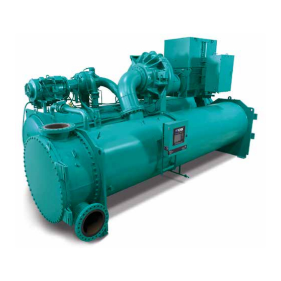
FORM 160.87-OM1 SECTION 1 - DESCRIPTION OF SYSTEM AND FUNDAMENTALS OF OPERATION ISSUE DATE: 8/24/2018 Refrigerant Flow-Thru Chiller LEGEND High Pressure Vapor High Pressure Liquid Refrigerant Low Pressure Vapor Low Pressure Liquid Refrigerant Intermediate Pressure Vapor Intermediate Pressure Liquid Refrigerant Primary Isolation Compressor... - Page 14 FORM 160.87-OM1 SECTION 1 - DESCRIPTION OF SYSTEM AND FUNDAMENTALS OF OPERATION ISSUE DATE: 8/24/2018 THIS PAGE INTENTIONALLY LEFT BLANK JOHNSON CONTROLS...
-
Page 15: Section 2 - Optiview Control Center Introduction
Building Automation Instructions for specific operations are provided on System (BAS), YORK Chillers not only work well in- many of the screens. dividually, but also as a team. This new protocol al-... - Page 16 FORM 160.87-OM1 SECTION 2 - OPTIVIEW CONTROL CENTER INTRODUCTION ISSUE DATE: 8/24/2018 The chiller operating program resides in the OptiView • zz – language package revision level (00, 01, etc) Control Center Microboard. The Control Center could • 031-03630-001 – Shipped in new production be equipped with the following Microboards: chillers after August 2016.
-
Page 17: Optiview Control Center
FORM 160.87-OM1 SECTION 2 - OPTIVIEW CONTROL CENTER INTRODUCTION ISSUE DATE: 8/24/2018 OPTIVIEW CONTROL CENTER LD18607 FIGURE 4 - OPTIVIEW CONTROL CENTER The OptiView™ Control Center display is highlighted Cursor Arrow keys are pro- by a full screen graphics display. This display is nested vided to allow movement on within a standard keypad, and is surrounded by SOFT screens which contain a large... -
Page 18: Display Only
FORM 160.87-OM1 SECTION 2 - OPTIVIEW CONTROL CENTER INTRODUCTION ISSUE DATE: 8/24/2018 The Programmable values and Navigation commands If the correct password is received, the user is autho- are also subject to access level restrictions as described rized with the appropriate access level. If an incorrect below. -
Page 19: Navigation
FORM 160.87-OM1 SECTION 2 - OPTIVIEW CONTROL CENTER INTRODUCTION ISSUE DATE: 8/24/2018 Manual Controls NAVIGATION Some keys are used to perform manual control func- In order to maximize the amount of values which the tions. These may involve manual control of items such panel can display to the user, and in order to place as the Pre-Rotation Vanes, variable orifice or oil pump those values in context, multiple screens have been... - Page 20 FORM 160.87-OM1 SECTION 2 - OPTIVIEW CONTROL CENTER INTRODUCTION ISSUE DATE: 8/24/2018 Home Screen (Page 22) System Screen (Page 25) Economizer (Page 27) History (Page 139) Evaporator (Page 29) History Details (Page 141) Condenser (Page 32) Security Log Screen (Page 142) Level Control (Page 36 - 38) Security Log Details Screen (Page 144) Heat Recovery (Page 36)
-
Page 21: Table 1 - Addresses And Associated Data
FORM 160.87-OM1 SECTION 2 - OPTIVIEW CONTROL CENTER INTRODUCTION ISSUE DATE: 8/24/2018 ANALOG INPUT RANGES The following table indicates the valid display range the < or > symbols will be displayed beside the mini- for each of the analog input values. In the event that the mum or maximum value, respectively. -
Page 22: Home Screen
FORM 160.87-OM1 SECTION 2 - OPTIVIEW CONTROL CENTER INTRODUCTION ISSUE DATE: 8/24/2018 HOME SCREEN LD22043 FIGURE 5 - HOME SCREEN OVERVIEW Primary Motor % Full Load Amps This displays the percentage of Full Load Amps uti- When the chiller system is powered on, the above de- lized by the primary motor. - Page 23 FORM 160.87-OM1 SECTION 2 - OPTIVIEW CONTROL CENTER INTRODUCTION ISSUE DATE: 8/24/2018 For fields requiring access level of SER- Print VICE. Qualified service technicians should Access Level Required: VIEW refer to the OptiView Control Center Use this key to generate a hard-copy report of the Service for operation instructions and ex- present system status.
- Page 24 FORM 160.87-OM1 SECTION 2 - OPTIVIEW CONTROL CENTER INTRODUCTION ISSUE DATE: 8/24/2018 NAVIGATION Motor A detailed view of the motor controller parameters, System specific to the controller type presently utilized on the Used to provide additional system information. chiller system. This allows programming of the current limit and the pulldown demand limit values.
-
Page 25: System Screen
FORM 160.87-OM1 SECTION 2 - OPTIVIEW CONTROL CENTER INTRODUCTION ISSUE DATE: 8/24/2018 SYSTEM SCREEN LD19523 FIGURE 6 - SYSTEM SCREEN OVERVIEW Chilled Liquid Temperature – Setpoint Displays the active temperature setpoint to which the This screen gives a general overview of common chill- chiller is controlling the evaporator liquid. - Page 26 FORM 160.87-OM1 SECTION 2 - OPTIVIEW CONTROL CENTER INTRODUCTION ISSUE DATE: 8/24/2018 Condenser Pressure PROGRAMMABLE Displays the refrigerant pressure in the condenser. None Condenser Saturation Temperature Displays the saturation temperature in the condenser. NAVIGATION Home Oil Sump Temperature Access Level Required: VIEW Displays the temperature of the oil in the sump.
-
Page 27: Economizer System
FORM 160.87-OM1 SECTION 2 - OPTIVIEW CONTROL CENTER INTRODUCTION ISSUE DATE: 8/24/2018 ECONOMIZER SYSTEM LD19526 FIGURE 7 - ECONOMIZER SYSTEM SCREEN OVERVIEW Primary PRV Position Displays how open the PRV vanes are in percentage This screen displays all parameters related to the Econ- from 100% (fully open) to 0% (fully closed). - Page 28 FORM 160.87-OM1 SECTION 2 - OPTIVIEW CONTROL CENTER INTRODUCTION ISSUE DATE: 8/24/2018 Economizer Motor Run (LED) Condenser Pressure Illuminates when the Economizer Compressor is cur- Displays the pressure of the refrigerant within the con- rently running. denser. Economizer Discharge Temperature Condenser Saturation Temperature Displays the temperature of the refrigerant vapor at the Displays the saturation temperature of the refrigerant...
-
Page 29: Evaporator Screen
FORM 160.87-OM1 SECTION 2 - OPTIVIEW CONTROL CENTER INTRODUCTION ISSUE DATE: 8/24/2018 EVAPORATOR SCREEN LD20158 FIGURE 8 - EVAPORATOR SCREEN OVERVIEW Return Chilled Liquid Temperature Displays the temperature of the liquid as it enters the This screen displays a cutaway view of the chiller evaporator. - Page 30 FORM 160.87-OM1 SECTION 2 - OPTIVIEW CONTROL CENTER INTRODUCTION ISSUE DATE: 8/24/2018 Leaving Chilled Liquid Temperature Setpoints Local Leaving Chilled Liquid Temperature – – Shutdown Setpoint Access Level Required: OPERATOR Displays the Leaving Chilled Liquid Temperature at which the chiller will shutdown on Leaving Chilled This value allows the user to define the Leaving Liquid –...
- Page 31 FORM 160.87-OM1 SECTION 2 - OPTIVIEW CONTROL CENTER INTRODUCTION ISSUE DATE: 8/24/2018 with smart freeze enabled) or 6°F (brine). For example, Brine Low Evaporator Cutout if the Leaving Chilled Liquid Temperature Setpoint is Access Level Required: SERVICE set to 45°F (water) and the Shutdown Setpoint is set This value is only available in Brine mode.
-
Page 32: Condenser Screen
FORM 160.87-OM1 SECTION 2 - OPTIVIEW CONTROL CENTER INTRODUCTION ISSUE DATE: 8/24/2018 CONDENSER SCREEN LD22045 FIGURE 9 - CONDENSER SCREEN OVERVIEW Condenser Pressure Displays the refrigerant pressure in the condenser. This screen displays a cutaway view of the chiller con- denser. - Page 33 FORM 160.87-OM1 SECTION 2 - OPTIVIEW CONTROL CENTER INTRODUCTION ISSUE DATE: 8/24/2018 Condenser Liquid Flow Switch Fault Acknowledge Indicates whether flow is present in the condenser. Access Level Required: SERVICE This allows clearing of the High Condenser Pressure Condenser Liquid Pump (Run / Stop) Fault while Shutdown (Condenser-High Pressure Stopped).
-
Page 34: Head Pressure Control Screen
FORM 160.87-OM1 SECTION 2 - OPTIVIEW CONTROL CENTER INTRODUCTION ISSUE DATE: 8/24/2018 HEAD PRESSURE CONTROL SCREEN LD20143 FIGURE 10 - HEAD PRESSURE CONTROL SCREEN OVERVIEW DISPLAY ONLY This screen displays all parameters related to the Head Entering Condenser Liquid Temperature Pressure Control feature. - Page 35 FORM 160.87-OM1 SECTION 2 - OPTIVIEW CONTROL CENTER INTRODUCTION ISSUE DATE: 8/24/2018 The actual value of the output signal for a given error Control Valve Output Settings – Auto depends on whether the PID OUTPUT Setpoint is set Places the Control Valve in automatic control. to direct or reverse.
-
Page 36: Refrigerant Level Control Screen
FORM 160.87-OM1 SECTION 2 - OPTIVIEW CONTROL CENTER INTRODUCTION ISSUE DATE: 8/24/2018 REFRIGERANT LEVEL CONTROL SCREEN LD22046 FIGURE 11 - REFRIGERANT LEVEL CONTROL SCREEN OVERVIEW TABLE 2 - CONDENSER LEVEL POSITION CONTROL VALVE This screen displays a cutaway view of the chiller con- ACTUAL LEVEL COMMAND % denser, along with the liquid refrigerant level sensor... - Page 37 FORM 160.87-OM1 SECTION 2 - OPTIVIEW CONTROL CENTER INTRODUCTION ISSUE DATE: 8/24/2018 This read box displays the remaining seconds until PID Close control. Pressing this button will set the Condenser Level Con- trol Valve Mode to Manual if it had been in Auto and Level Control Valve Command will decrease the current Condenser Level Control Indicates the valve command as a percentage of full...
-
Page 38: Primary Compressor Screen
FORM 160.87-OM1 SECTION 2 - OPTIVIEW CONTROL CENTER INTRODUCTION ISSUE DATE: 8/24/2018 PRIMARY COMPRESSOR SCREEN 00549VIP FIGURE 12 - PRIMARY COMPRESSOR SCREEN OVERVIEW DISPLAY ONLY This screen displays a cutaway view of the chiller com- Oil Pressure pressor, revealing the impeller, and shows all condi- Displays the pressure differential between the high tions associated with the compressor. - Page 39 FORM 160.87-OM1 SECTION 2 - OPTIVIEW CONTROL CENTER INTRODUCTION ISSUE DATE: 8/24/2018 from the differential pressure. The offset pressure cal- Full Load Amps culation will not be performed if either transducer is Access Level Required: SERVICE out of range. The offset value will be taken as 0 PSI in Displays the motor current as a percentage of the Full this instance.
- Page 40 FORM 160.87-OM1 SECTION 2 - OPTIVIEW CONTROL CENTER INTRODUCTION ISSUE DATE: 8/24/2018 NAVIGATION Hot Gas Access Level Required: SERVICE Home Moves to a subscreen that allows programming of the Access Level Required: VIEW Hot Gas Bypass control setpoints and manual control of Returns user to HOME Screen.
-
Page 41: Economizer Compressor Screen
FORM 160.87-OM1 SECTION 2 - OPTIVIEW CONTROL CENTER INTRODUCTION ISSUE DATE: 8/24/2018 ECONOMIZER COMPRESSOR SCREEN LD19628 FIGURE 13 - ECONOMIZER COMPRESSOR SCREEN OVERVIEW The offset pressure is the pressure differential between the high oil pressure (HOP) transducer and the low This screen displays a cutaway view of the Econo- oil pressure (LOP) transducer outputs during a three mizer compressor, revealing the impeller, and shows... - Page 42 FORM 160.87-OM1 SECTION 2 - OPTIVIEW CONTROL CENTER INTRODUCTION ISSUE DATE: 8/24/2018 Discharge Superheat Compressor Time Displays the discharge superheat, calculated as (Discharge Access Level Required: SERVICE This value displays the economizer compressor time in Temperature – Condenser Saturation temperature). use or time remaining of the active compressor status High Speed Thrust Bearing Limit Switch LED level.
- Page 43 FORM 160.87-OM1 SECTION 2 - OPTIVIEW CONTROL CENTER INTRODUCTION ISSUE DATE: 8/24/2018 Capacity Control Access Level Required: SERVICE Navigates to CAPACITY CONTROL Screen. Motor Access Level Required: SERVICE Moves to a subscreen that allows programming of the Hot Gas Bypass control setpoints and manual control of the Hot Gas Bypass valve.
-
Page 44: Economizer Operation Screen
FORM 160.87-OM1 SECTION 2 - OPTIVIEW CONTROL CENTER INTRODUCTION ISSUE DATE: 8/24/2018 ECONOMIZER OPERATION SCREEN LD20145 FIGURE 14 - ECONOMIZER OPERATIONS SCREEN OVERVIEW Number of starts. Access Level Required: ADMIN Access Level Required: SERVICE Displays the number of starts that the economizer com- This screen shows various settings and information pressor has accumulated. -
Page 45: Economizer Prv Calibration Screen
FORM 160.87-OM1 SECTION 2 - OPTIVIEW CONTROL CENTER INTRODUCTION ISSUE DATE: 8/24/2018 ECONOMIZER PRV CALIBRATION SCREEN LD19631 FIGURE 15 - ECONOMIZER PRV CALIBRATION SCREEN OVERVIEW PRV Feedback Voltage Displays the feedback voltage on the PRV motor. This screen displays a cutaway view of the chiller econo- mizer compressor, revealing the Pre-Rotation Vanes and PRV Calibration State provides the capability of calibrating the Pre-Rotation... - Page 46 FORM 160.87-OM1 SECTION 2 - OPTIVIEW CONTROL CENTER INTRODUCTION ISSUE DATE: 8/24/2018 PRV Position Hold Displays the position of the Pre-Rotation Vanes in per- Pressing this button will hold the Pre-Rotation Vanes cent over the range of 0% (full close) to 100% (full in a set position.
-
Page 47: Economizer Screen
FORM 160.87-OM1 SECTION 2 - OPTIVIEW CONTROL CENTER INTRODUCTION ISSUE DATE: 8/24/2018 ECONOMIZER SCREEN LD19632 FIGURE 16 - ECONOMIZER SCREEN OVERVIEW Economizer Pressure Displays the economizer pressure of the economizer. This screen displays a cutaway view of the chiller econo- mizer, revealing the economizer interior and the econo- Saturation Temperature mizer refrigerant level control. - Page 48 FORM 160.87-OM1 SECTION 2 - OPTIVIEW CONTROL CENTER INTRODUCTION ISSUE DATE: 8/24/2018 Level Control Valve Command Open Displays the state of the Level Control Valve in percent Access Level Required: SERVICE Pressing this button will set the Economizer Level of open, where 100.0% is fully open and 0.0% is fully closed.
-
Page 49: Proximity Probe Calibration Screen
FORM 160.87-OM1 SECTION 2 - OPTIVIEW CONTROL CENTER INTRODUCTION ISSUE DATE: 8/24/2018 PROXIMITY PROBE CALIBRATION SCREEN (CHILLERS WITH J OR H3 COMPRESSORS) 00305VIP FIGURE 17 - PROXIMITY PROBE CALIBRATION SCREEN (CHILLERS WITH J OR H3 COMPRESSORS) OVERVIEW Oil Pressure Displays the pressure differential between the high This screen displays a cutaway view of the chiller com- side oil pressure transducer (compressor bearing input) pressor, revealing the Proximity Probe sensor and provides... - Page 50 FORM 160.87-OM1 SECTION 2 - OPTIVIEW CONTROL CENTER INTRODUCTION ISSUE DATE: 8/24/2018 Start Calibration NAVIGATION Press this key to start the calibration. Home Access Level Required: VIEW Cancel Calibration Returns user to HOME Screen. Press this key to cancel calibration. Compressor Accept Calibration Access Level Required: VIEW...
-
Page 51: Hot Gas Bypass Screen
FORM 160.87-OM1 SECTION 2 - OPTIVIEW CONTROL CENTER INTRODUCTION ISSUE DATE: 8/24/2018 HOT GAS BYPASS SCREEN LD20146 FIGURE 18 - HOT GAS BYPASS SCREEN OVERVIEW TABLE 3 - VALVE POSITION ACTUAL POSITION VALVE POSITION % This screen displays a cutaway view of the Hot Gas By- 0% to 19% 0% (fully closed) pass Valve. - Page 52 FORM 160.87-OM1 SECTION 2 - OPTIVIEW CONTROL CENTER INTRODUCTION ISSUE DATE: 8/24/2018 Surge Avoidance Surge Count Minimum Load This is the total number of surges accumulated by the Access Level Required: SERVICE (0 to 4°F; default 0°F) Surge Protection feature. If equipped with a VSD or MVVSD, it is only the surges detected while the drive This sets the offset below the Leaving Chilled Liquid is running at maximum frequency.
-
Page 53: Surge Protection Screen
FORM 160.87-OM1 SECTION 2 - OPTIVIEW CONTROL CENTER INTRODUCTION ISSUE DATE: 8/24/2018 SURGE PROTECTION SCREEN LD22059 FIGURE 19 - SURGE PROTECTION SCREEN OVERVIEW Surge Detection creates a surge map used to control the speed of the drive. The ACC Surge Detection is per- This screen displays a cutaway view of the chiller com- formed in the Microboard pressor and all parameters relating to the Surge Pro-... - Page 54 FORM 160.87-OM1 SECTION 2 - OPTIVIEW CONTROL CENTER INTRODUCTION ISSUE DATE: 8/24/2018 Surge Window Count If this setpoint is Disabled, refer to operation under Count Limit on Page 55. Displays the number of surge events that have occurred in the last 1 to 5 minutes as programmed with the Count •...
- Page 55 FORM 160.87-OM1 SECTION 2 - OPTIVIEW CONTROL CENTER INTRODUCTION ISSUE DATE: 8/24/2018 Count Limit Surge Sensitivity Access Level Required: OPERATOR Access Level Required: SERVICE Allows the user to define the maximum number of surge Allows the user to define the surge detection sensitivity events (4 to 20;...
-
Page 56: Variable Geometry Diffuser Screen
FORM 160.87-OM1 SECTION 2 - OPTIVIEW CONTROL CENTER INTRODUCTION ISSUE DATE: 8/24/2018 VARIABLE GEOMETRY DIFFUSER SCREEN LD15427 FIGURE 20 - VARIABLE GEOMETRY DIFFUSER SCREEN OVERVIEW VGD Closed Limit Switch Displays the status of the VGD Limit Switch. Dis- This screen displays information pertinent to the VGD played as CLOSED when the switch is closed. - Page 57 FORM 160.87-OM1 SECTION 2 - OPTIVIEW CONTROL CENTER INTRODUCTION ISSUE DATE: 8/24/2018 VGD Count [VGD] Close (Manual) Displays the number of times the Stall Detector Board Access Level Required: SERVICE output voltage goes above the High Limit Setpoint. This key puts the VGD in manual mode and sends a The count can be cleared with an ADMIN access lev- CLOSE command to the VGD.
-
Page 58: Variable Geometry Diffuser Setpoints Screen
FORM 160.87-OM1 SECTION 2 - OPTIVIEW CONTROL CENTER INTRODUCTION ISSUE DATE: 8/24/2018 VARIABLE GEOMETRY DIFFUSER SETPOINTS SCREEN LD15428 FIGURE 21 - VARIABLE GEOMETRY DIFFUSER SETPOINTS SCREEN OVERVIEW Pre-Rotation Vanes Position Displays the position of the Pre-Rotation Vanes over The Variable Geometry Diffuser setpoints are main- the range of 0% (fully closed) to 100% (fully open). - Page 59 FORM 160.87-OM1 SECTION 2 - OPTIVIEW CONTROL CENTER INTRODUCTION ISSUE DATE: 8/24/2018 ACC Surge Detected (LED) High Limit Only displayed if equipped with a VSD or MVVSD. (0.5 to 1.2VDC; default 0.6VDC – Specifies the Stall Illuminates momentarily when a surge is detected by Detector Board output voltage that represents an ac- the ACC function in the Microboard, while the drive is ceptable amount of stall noise.
-
Page 60: Economizer Compressor Variable Geometry Diffuser Screen
FORM 160.87-OM1 SECTION 2 - OPTIVIEW CONTROL CENTER INTRODUCTION ISSUE DATE: 8/24/2018 ECONOMIZER COMPRESSOR VARIABLE GEOMETRY DIFFUSER SCREEN LD19633 FIGURE 22 - ECONOMIZER COMPRESSOR VGD SCREEN OVERVIEW VGD Closed Limit Switch Displays the status of the VGD Limit Switch. Dis- This screen displays information pertinent to the Econ- played as CLOSED when the switch is closed. - Page 61 FORM 160.87-OM1 SECTION 2 - OPTIVIEW CONTROL CENTER INTRODUCTION ISSUE DATE: 8/24/2018 Discharge Pressure Open (with LED) Displays the current discharge pressure of the econo- Access Level Required: SERVICE Pressing this button will send a command to open the mizer compressor. VGD.
-
Page 62: Economizer Vgd Setpoints Screen
FORM 160.87-OM1 SECTION 2 - OPTIVIEW CONTROL CENTER INTRODUCTION ISSUE DATE: 8/24/2018 ECONOMIZER VGD SETPOINTS SCREEN LD19634 FIGURE 23 - ECONOMIZER VGD SETPOINTS SCREEN OVERVIEW VGD Closed Limit Switch Displays the status of the VGD Limit Switch. Dis- This screen displays information for the Economizer played as CLOSED when the switch is closed. - Page 63 FORM 160.87-OM1 SECTION 2 - OPTIVIEW CONTROL CENTER INTRODUCTION ISSUE DATE: 8/24/2018 VGD Control State Stall Wait Time Shows the current state of the VGD Control. It will Access Level Required: SERVICE (0.5 to 15 minutes, Default 10 minutes) show various messages as follows: After the VGD control detects a stall and enters Stall Undefined Wait State.
-
Page 64: Pre-Rotation Vanes Calibration Screen
FORM 160.87-OM1 SECTION 2 - OPTIVIEW CONTROL CENTER INTRODUCTION ISSUE DATE: 8/24/2018 PRE-ROTATION VANES CALIBRATION SCREEN LD20148 FIGURE 24 - PRE-ROTATION VANES CALIBRATION SCREEN OVERVIEW Pre-Rotation Vanes Voltage Displays the Pre-Rotation Vanes position potentiom- This screen displays a cutaway view of the chiller com- eter feedback voltage. -
Page 65: Vsd Tuning Screen
FORM 160.87-OM1 SECTION 2 - OPTIVIEW CONTROL CENTER INTRODUCTION ISSUE DATE: 8/24/2018 VSD TUNING SCREEN LD13828 FIGURE 25 - VSD TUNING SCREEN OVERVIEW Delta P/P Displays the chiller head pressure calculated as (con- This screen applies to both Variable Speed Drives denser pressure - evaporator pressure/evaporator pres- (VSD) and Medium Voltage Variable Speed Drives sure). - Page 66 FORM 160.87-OM1 SECTION 2 - OPTIVIEW CONTROL CENTER INTRODUCTION ISSUE DATE: 8/24/2018 Pre-Rotation Vanes Control Mode Lower Indicates whether the vanes are under manual or auto- Access Level Required: SERVICE matic control. Puts the drive frequency control into manual mode. Each time it is pressed it lowers the Command Fre- [Pre-Rotation Vanes] Open (LED) quency to the drive by the amount defined by the...
-
Page 67: Oil Sump Screen
FORM 160.87-OM1 SECTION 2 - OPTIVIEW CONTROL CENTER INTRODUCTION ISSUE DATE: 8/24/2018 OIL SUMP SCREEN LD19635 FIGURE 26 - OIL SUMP SCREEN OVERVIEW Oil – Saturated Condenser Temperature Differential This screen displays a close-up of the chiller oil sump (Variable Speed Oil Pump Only) and provides all the necessary setpoints for maintain- ing the Variable Speed Oil Pump (VSOP). - Page 68 FORM 160.87-OM1 SECTION 2 - OPTIVIEW CONTROL CENTER INTRODUCTION ISSUE DATE: 8/24/2018 Oil Seal Lubrication Time Remaining Pressure Setpoint (Variable Speed Oil Pump Only) Access Level Required: SERVICE If a Seal Lubrication is in progress, this will display the Access Level Required: SERVICE amount of time remaining in the lubrication process.
-
Page 69: Economizer Oil Pump Screen
FORM 160.87-OM1 SECTION 2 - OPTIVIEW CONTROL CENTER INTRODUCTION ISSUE DATE: 8/24/2018 ECONOMIZER OIL PUMP SCREEN LD22047 FIGURE 27 - ECONOMIZER OIL PUMP SCREEN OVERVIEW Sump Oil Pressure (LOP) Displays the low side oil pressure measured at the This screen displays a close-up of the chiller econo- sump. - Page 70 FORM 160.87-OM1 SECTION 2 - OPTIVIEW CONTROL CENTER INTRODUCTION ISSUE DATE: 8/24/2018 Next Oil Seal Lubrication Pressure Setpoint (Variable Speed Oil Pump Only) Access Level Required: SERVICE This display will show the time remaining until the Access Level Required: SERVICE next Seal Lubrication is necessary, when this function The Variable Speed Oil Pump (VSOP) operates to con- is enabled.
-
Page 71: Economizer Capacity Control Screen
FORM 160.87-OM1 SECTION 2 - OPTIVIEW CONTROL CENTER INTRODUCTION ISSUE DATE: 8/24/2018 ECONOMIZER CAPACITY CONTROL SCREEN LD19637 FIGURE 28 - ECONOMIZER CAPACITY CONTROL SCREEN OVERVIEW Motor Current % FLA Displays the percent of full load amps of the econo- This screen displays a view of the economizer capacity mizer compressor motor. - Page 72 FORM 160.87-OM1 SECTION 2 - OPTIVIEW CONTROL CENTER INTRODUCTION ISSUE DATE: 8/24/2018 Control State Decrease Displays the control state that the economizer is oper- Access Level Required: SERVICE Pressing this button with activate the economizer Pre- ating. It could show Inactive, Cooling Control, or Mo- tor Current, depending on the panels Capacity Control Rotation Vane override and set it to Manual if it was State.
-
Page 73: Economizer Capacity Control Setpoints Screen
FORM 160.87-OM1 SECTION 2 - OPTIVIEW CONTROL CENTER INTRODUCTION ISSUE DATE: 8/24/2018 ECONOMIZER CAPACITY CONTROL SETPOINTS SCREEN LD20149 FIGURE 29 - ECONOMIZER CAPACITY CONTROL SETPOINTS SCREEN OVERVIEW Refrigerant Flow Criteria at Low Head (Range 100 to 50000 CFM, Default 8200 CFM) This screen displays a view of the economizer capacity control setpoints and buttons. - Page 74 FORM 160.87-OM1 SECTION 2 - OPTIVIEW CONTROL CENTER INTRODUCTION ISSUE DATE: 8/24/2018 Econ Level High Shutdown Econ Temperature Control Kp (Range 80 to 100%, Default 95%) (Range 0.1 to 15.0, Default 5.0) Displays the position of the Pre-Rotation Vanes at full Adjusts the Proportional Gain.
-
Page 75: Economizer Anti-Surge Tuning Screen
FORM 160.87-OM1 SECTION 2 - OPTIVIEW CONTROL CENTER INTRODUCTION ISSUE DATE: 8/24/2018 ECONOMIZER ANTI-SURGE TUNING SCREEN LD19643 FIGURE 30 - ECONOMIZER ANTI-SURGE TUNING SCREEN • Min Temperature Rate Maximum OVERVIEW This screen will show all the data and settings relating •... - Page 76 FORM 160.87-OM1 SECTION 2 - OPTIVIEW CONTROL CENTER INTRODUCTION ISSUE DATE: 8/24/2018 NAVIGATION Home Access Level Required: VIEW Returns the user to the HOME Screen. Capacity Control Access Level Required: SERVICE Allows the user to navigate to the Economizer Capac- ity Control Screen..
-
Page 77: Condenser Refrigerant Level Control Screen
FORM 160.87-OM1 SECTION 2 - OPTIVIEW CONTROL CENTER INTRODUCTION ISSUE DATE: 8/24/2018 CONDENSER REFRIGERANT LEVEL CONTROL SCREEN LD19646 FIGURE 31 - CONDENSER REFRIGERANT LEVEL CONTROL SCREEN OVERVIEW TABLE 4 - CONDENSER REFRIGERANT LEVEL ACTUAL LEVEL CONTROL VALVE COMMAND % This screen shows the data and settings related to the 0% to 15% Condenser Refrigerant Level Control. - Page 78 FORM 160.87-OM1 SECTION 2 - OPTIVIEW CONTROL CENTER INTRODUCTION ISSUE DATE: 8/24/2018 PROGRAMMABLE Access Level Required: ADMIN Level Setpoint Sets the Derivative value of the PID control loop. (Ad- Access Level Required: SERVICE justable 0.0 to 200; default 0.0). Displays the Condenser Level Control Setpoint for the Manual Increment PID control.
-
Page 79: Economizer Solid State Starter Screen
FORM 160.87-OM1 SECTION 2 - OPTIVIEW CONTROL CENTER INTRODUCTION ISSUE DATE: 8/24/2018 ECONOMIZER SOLID STATE STARTER SCREEN LD19648 FIGURE 32 - ECONOMIZER SOLID STATE STARTER SCREEN OVERVIEW Starter Model Displays the Solid State Starter model that is applied The Economizer Solid State Starter Screen displays to the chiller. - Page 80 FORM 160.87-OM1 SECTION 2 - OPTIVIEW CONTROL CENTER INTRODUCTION ISSUE DATE: 8/24/2018 Voltage Range NAVIGATION Access Level Required: SERVICE Home Allows the user to select specific line voltage range for Access Level Required: VIEW voltage checking. When not disabled, this line voltage Returns user to HOME Screen.
-
Page 81: Electro-Mechanical Starter Screen
FORM 160.87-OM1 SECTION 2 - OPTIVIEW CONTROL CENTER INTRODUCTION ISSUE DATE: 8/24/2018 ELECTRO-MECHANICAL STARTER SCREEN LD20151 FIGURE 33 - ELECTRO-MECHANICAL STARTER SCREEN OVERVIEW PROGRAMMABLE This screen displays all information pertaining to the Local Motor Current Limit Electro-Mechanical Starter. Access Level Required: OPERATOR Allows the user to specify the maximum allowed mo- tor current (as a percentage of FLA). - Page 82 FORM 160.87-OM1 SECTION 2 - OPTIVIEW CONTROL CENTER INTRODUCTION ISSUE DATE: 8/24/2018 NAVIGATION Home Access Level Required: VIEW Returns user to HOME Screen. Motor Lube Access Level Required: VIEW Moves to the subscreen allowing operator acknowledge- ment of the compressor motor lubrication and viewing of the compressor motor lubrication parameters.
-
Page 83: Mod "A" Solid State Starter Screen
FORM 160.87-OM1 SECTION 2 - OPTIVIEW CONTROL CENTER INTRODUCTION ISSUE DATE: 8/24/2018 MOD “A” SOLID STATE STARTER SCREEN LD22048 FIGURE 34 - MOD “A” SOLID STATE STARTER SCREEN OVERVIEW Pulldown Demand Time Left Displays the time remaining in the programmed This screen displays all information pertaining to the pulldown period if the value is nonzero. - Page 84 FORM 160.87-OM1 SECTION 2 - OPTIVIEW CONTROL CENTER INTRODUCTION ISSUE DATE: 8/24/2018 will not be permitted to open further. If the motor cur- Current Unbalance Check (Enabled / Disabled) rent rises above this value, the Pre-Rotation Vanes will Access Level Required: SERVICE close to reduce the current to this value.
-
Page 85: Economizer Solid State Starter Screen
FORM 160.87-OM1 SECTION 2 - OPTIVIEW CONTROL CENTER INTRODUCTION ISSUE DATE: 8/24/2018 ECONOMIZER SOLID STATE STARTER SCREEN LD22050 FIGURE 35 - ECONOMIZER SOLID STATE STARTER SCREEN OVERVIEW Pulldown Demand Time Left Displays the time remaining in the programmed This screen displays all information pertaining to the pulldown period. - Page 86 Access Level Required: SERVICE Allows the user to enable or disable the Solid State pressor information. Starter Open SCR safety detection. This must never be disabled unless under advisement of the YORK Factory. Shorted SCR (Enabled/Disabled) Access Level Required: SERVICE Allows the user to enable or disable the Solid State Starter Shorted SCR safety detection.
-
Page 87: Medium Voltage Solid State Starter Screen
FORM 160.87-OM1 SECTION 2 - OPTIVIEW CONTROL CENTER INTRODUCTION ISSUE DATE: 8/24/2018 MEDIUM VOLTAGE SOLID STATE STARTER SCREEN LD22049 FIGURE 36 - MEDIUM VOLTAGE SOLID STATE STARTER SCREEN OVERVIEW Input Power Displays the kilowatts measured by and transmitted This screen displays all information pertinent to the from the starter. - Page 88 FORM 160.87-OM1 SECTION 2 - OPTIVIEW CONTROL CENTER INTRODUCTION ISSUE DATE: 8/24/2018 PROGRAMMABLE NAVIGATION Local Motor Current Limit Home Access Level Required: OPERATOR Access Level Required: VIEW Allows the user to specify the maximum allowed mo- Returns user to HOME Screen. tor current (as a percentage of FLA).
-
Page 89: Variable Speed Drive Screen
FORM 160.87-OM1 SECTION 2 - OPTIVIEW CONTROL CENTER INTRODUCTION ISSUE DATE: 8/24/2018 VARIABLE SPEED DRIVE SCREEN LD20155 FIGURE 37 - VARIABLE SPEED DRIVE SCREEN OVERVIEW Pulldown Demand Time Left Displays the time remaining in the programmed This screen displays information pertaining to a Vari- pulldown period if the value is nonzero. - Page 90 FORM 160.87-OM1 SECTION 2 - OPTIVIEW CONTROL CENTER INTRODUCTION ISSUE DATE: 8/24/2018 PROGRAMMABLE NAVIGATION Local Motor Current Limit Home Access Level Required: OPERATOR Access Level Required: VIEW Allows the user to specify the maximum allowed mo- Returns user to HOME Screen. tor current (as a percentage of FLA).
-
Page 91: Medium Voltage Variable Speed Drive Screen
FORM 160.87-OM1 SECTION 2 - OPTIVIEW CONTROL CENTER INTRODUCTION ISSUE DATE: 8/24/2018 MEDIUM VOLTAGE VARIABLE SPEED DRIVE SCREEN LD20156 FIGURE 38 - MEDIUM VOLTAGE VARIABLE SPEED DRIVE SCREEN OVERVIEW Current Limit Setpoint Displays the current limit value in use. This value could This screen displays information pertaining to a Me- come from a 0 to 20mA, 4 to 20mA, 0 to 10VDC or 2 dium Voltage Variable Speed Drive (MVVSD). -
Page 92: Table 5 - Voltage (V)
FORM 160.87-OM1 SECTION 2 - OPTIVIEW CONTROL CENTER INTRODUCTION ISSUE DATE: 8/24/2018 Input Power TABLE 5 - VOLTAGE (V) Displays the total kilowatts measured by the MVVSD. MOTOR RATED VOLTAGE (V) Value is provided by the MVVSD. 2300 V 3300 V 4160 V 107 A 78 A... - Page 93 FORM 160.87-OM1 SECTION 2 - OPTIVIEW CONTROL CENTER INTRODUCTION ISSUE DATE: 8/24/2018 PROGRAMMABLE KWH Reset Access Level Required: SERVICE Local Motor Current Limit Allows the user to reset the cumulative Kilowatt hours Access Level Required: OPERATOR to zero. Allows the user to specify the maximum allowed mo- tor current (as a percentage of FLA).
-
Page 94: Variable Speed Drive (Vsd) Details Screen
FORM 160.87-OM1 SECTION 2 - OPTIVIEW CONTROL CENTER INTRODUCTION ISSUE DATE: 8/24/2018 VARIABLE SPEED DRIVE (VSD) DETAILS SCREEN LD09096 FIGURE 39 - VARIABLE SPEED DRIVE (VSD) DETAILS SCREEN OVERVIEW Current Limit Setpoint Displays the current limit value in use. This value This screen displays more detailed information per- could come from a 0 to 20mA, 4 to 20mA, 0 to 10VDC taining to a Variable Speed Drive (VSD)part number... - Page 95 FORM 160.87-OM1 SECTION 2 - OPTIVIEW CONTROL CENTER INTRODUCTION ISSUE DATE: 8/24/2018 DC Bus Voltage PROGRAMMABLE Displays the DC Bus voltage as reported by the VSD. Local Motor Current Limit Access Level Required: OPERATOR DC Inverter Link Current Allows the user to specify the maximum allowed mo- Displays the DC Inverter link current as reported by tor current (as a percentage of FLA).
-
Page 96: Variable Speed Drive (Vsd) Details Screen
FORM 160.87-OM1 SECTION 2 - OPTIVIEW CONTROL CENTER INTRODUCTION ISSUE DATE: 8/24/2018 VARIABLE SPEED DRIVE (VSD) DETAILS SCREEN (VSD WITH PART NUMBER 371-02767-XXX (60 HZ) OR 371-03700-XXX (50 HZ)) 00665VIP FIGURE 40 - VARIABLE SPEED DRIVE (VSD) DETAILS SCREEN (VSD WITH PART NUMBER 371-02767-XXX (60 HZ) OR 371-03700-XXX (50 HZ)) OVERVIEW Current Limit Setpoint... - Page 97 FORM 160.87-OM1 SECTION 2 - OPTIVIEW CONTROL CENTER INTRODUCTION ISSUE DATE: 8/24/2018 DC Bus Voltage PROGRAMMABLE Displays the DC Bus voltage as reported by the VSD. Local Motor Current Limit Access Level Required: OPERATOR DC Inverter Link Current Allows the user to specify the maximum allowed mo- Displays the DC Inverter link current as reported by tor current (as a percentage of FLA).
-
Page 98: Adaptive Capacity Control Details Screen
FORM 160.87-OM1 SECTION 2 - OPTIVIEW CONTROL CENTER INTRODUCTION ISSUE DATE: 8/24/2018 ADAPTIVE CAPACITY CONTROL DETAILS SCREEN MODBUS PROTOCOL CONFIGURATION LD14339 FIGURE 41 - ADAPTIVE CAPACITY CONTROL DETAILS SCREEN MODBUS PROTOCOL CONFIGURATION OVERVIEW DISPLAY ONLY This screen displays detailed information pertaining % Full Load Amps to the Adaptive Capacity Control (ACC). - Page 99 FORM 160.87-OM1 SECTION 2 - OPTIVIEW CONTROL CENTER INTRODUCTION ISSUE DATE: 8/24/2018 Pre-Rotation Vanes Position PROGRAMMABLE Displays the present Pre-Rotation Vane position as a VSD Start Frequency value between 0% (closed) and 100% (full open). Sets the starting frequency from which the ramp-up will begin.
- Page 100 FORM 160.87-OM1 SECTION 2 - OPTIVIEW CONTROL CENTER INTRODUCTION ISSUE DATE: 8/24/2018 Surge Map Print Allows the Service Technician to print the entire surge Access Level Required: VIEW map to a connected printer, as shown in SECTION 4 - Returns user to VSD Screen. PRINTING of this manual.
-
Page 101: Surge Map Screen - Table View
FORM 160.87-OM1 SECTION 2 - OPTIVIEW CONTROL CENTER INTRODUCTION ISSUE DATE: 8/24/2018 SURGE MAP SCREEN - TABLE VIEW LD15430 FIGURE 42 - SURGE MAP SCREEN - TABLE VIEW Setpoint set to MODBUS; ACC Board is not present) OVERVIEW and Medium Voltage Variable Speed Drives (MV- The surge map can be shown in either Table (default) or VSD). - Page 102 FORM 160.87-OM1 SECTION 2 - OPTIVIEW CONTROL CENTER INTRODUCTION ISSUE DATE: 8/24/2018 Speed Decrease Inhibit – Surge Map Point Manual Surge Point (LED) Allows the Service Technician to manually log the Illuminates when the Microboard ACC function is not present running conditions into the surge map as a val- permitted to reduce speed due to a mapped surge point.
-
Page 103: Surge Map Screen - List View
FORM 160.87-OM1 SECTION 2 - OPTIVIEW CONTROL CENTER INTRODUCTION ISSUE DATE: 8/24/2018 SURGE MAP SCREEN - LIST VIEW LD13833 FIGURE 43 - SURGE MAP SCREEN - LIST VIEW Requires a login access level of SERVICE. OVERVIEW The surge map can be shown in either Table (default) or List view as selected with the MAP VIEW key. - Page 104 FORM 160.87-OM1 SECTION 2 - OPTIVIEW CONTROL CENTER INTRODUCTION ISSUE DATE: 8/24/2018 NAVIGATION Home Returns user to HOME Screen. Returns user to VSD Screen. ACC Details Returns user to ACC DETAILS Screen. JOHNSON CONTROLS...
-
Page 105: Harmonic Filter Details Screen
FORM 160.87-OM1 SECTION 2 - OPTIVIEW CONTROL CENTER INTRODUCTION ISSUE DATE: 8/24/2018 HARMONIC FILTER DETAILS SCREEN LD15431 FIGURE 44 - HARMONIC FILTER DETAILS SCREEN OVERVIEW Pulldown Demand Time Left Displays the time remaining in the programmed This screen displays more detailed information per- pulldown period if the value is nonzero. - Page 106 FORM 160.87-OM1 SECTION 2 - OPTIVIEW CONTROL CENTER INTRODUCTION ISSUE DATE: 8/24/2018 Precharge Contactor (LED) PROGRAMMABLE Indicates whether the output to the Precharge Contactor Local Motor Current Limit is energized. Access Level Required: OPERATOR Allows the user to specify the maximum allowed mo- Phase Rotation tor current (as a percentage of FLA).
-
Page 107: Motor Lubrication Screen
FORM 160.87-OM1 SECTION 2 - OPTIVIEW CONTROL CENTER INTRODUCTION ISSUE DATE: 8/24/2018 MOTOR LUBRICATION SCREEN LD10702 FIGURE 45 - MOTOR LUBRICATION SCREEN OVERVIEW DISPLAY ONLY This feature provides an indication when the compressor Date of Last Motor Lubrication Warning or motor lubrication is required. - Page 108 FORM 160.87-OM1 SECTION 2 - OPTIVIEW CONTROL CENTER INTRODUCTION ISSUE DATE: 8/24/2018 zero whenever the Operating hours (on the OPERA- • When all of the desired characters have been en- TIONS Screen) is reset to zero or whenever the Op- tered, press the ENTER () key.
-
Page 109: Motor Details Screen
FORM 160.87-OM1 SECTION 2 - OPTIVIEW CONTROL CENTER INTRODUCTION ISSUE DATE: 8/24/2018 MOTOR DETAILS SCREEN LD10702a FIGURE 46 - MOTOR DETAILS SCREEN OVERVIEW DISPLAY ONLY This screen displays information pertinent to the Mo- Motor Run (LED) tor Monitoring feature. The feature consists of motor Illuminates when the OptiView Control Center is com- winding temperature, motor bearing temperature, mo- manding the motor to run. - Page 110 FORM 160.87-OM1 SECTION 2 - OPTIVIEW CONTROL CENTER INTRODUCTION ISSUE DATE: 8/24/2018 Motor Windings Vibration Displays the Shaft End and Opposite End vibration val- Temperature ues. The vibration values are not in any particular units Displays the enabled Motor Winding Temperatures for of measure.
- Page 111 FORM 160.87-OM1 SECTION 2 - OPTIVIEW CONTROL CENTER INTRODUCTION ISSUE DATE: 8/24/2018 If no baseline values are entered, by either the auto Bearing Temperature Protection baseline routine or manual entry, the message WARN- Access Level Required: SERVICE ING – MOTOR – BEARING VIBRATION BASE- Enables the type of temperature sensing device being LINE NOT SET is displayed and the baseline values used to sense motor bearing temperature.
- Page 112 FORM 160.87-OM1 SECTION 2 - OPTIVIEW CONTROL CENTER INTRODUCTION ISSUE DATE: 8/24/2018 manual entry or by running the auto baseline rou- larger the number, the greater the magnitude of vibra- tine are shown, along with the AUTO BASELINE tion represented. Values entered appear on this screen and AUTO BASELINE SETPOINT keys.
-
Page 113: Motor Setpoints Screen
FORM 160.87-OM1 SECTION 2 - OPTIVIEW CONTROL CENTER INTRODUCTION ISSUE DATE: 8/24/2018 MOTOR SETPOINTS SCREEN LD10702b FIGURE 47 - MOTOR SETPOINTS SCREEN OVERVIEW Winding Hotspot Allowance Displays the Winding Hotspot Allowance temperature. This screen allows programming of the winding and Not shown when Winding Temperature Protection bearing High Temperature Warning/Safety Shutdown Setpoint on the MOTOR DETAILS Screen is set to... - Page 114 FORM 160.87-OM1 SECTION 2 - OPTIVIEW CONTROL CENTER INTRODUCTION ISSUE DATE: 8/24/2018 ues entered by the Vibration Setup Setpoint or values Winding Setup derived from the Vibration Baseline Setpoints (refer to Access Level Required: SERVICE Vibration Setup on Page 114). Also displayed is the Not shown when Winding Temperature Protection Delay, which is the amount of time the vibration must Setpoint on MOTOR DETAILS Screen is set to Dis-...
- Page 115 FORM 160.87-OM1 SECTION 2 - OPTIVIEW CONTROL CENTER INTRODUCTION ISSUE DATE: 8/24/2018 The Vibration Baseline values from which the Vibra- Vibration Gain tion Shutdown and Warning thresholds are derived, Access Level Required: ADMIN are displayed on the MOTOR DETAILS Screen. The Only shown when access level is ADMIN and Motor thresholds are calculated from the Baseline values as Vibration Protection Setpoint on MOTOR DETAILS...
-
Page 116: Setpoints Screen
FORM 160.87-OM1 SECTION 2 - OPTIVIEW CONTROL CENTER INTRODUCTION ISSUE DATE: 8/24/2018 SETPOINTS SCREEN LD14342 FIGURE 48 - SETPOINTS SCREEN OVERVIEW Offset – Shutdown from the Leaving Chilled Liquid Temperature – Setpoint. If this value is below the abso- This screen provides a convenient location for pro- lute minimum allowed shutdown temperature the mini- gramming the most common setpoints involved in the mum value is displayed. - Page 117 FORM 160.87-OM1 SECTION 2 - OPTIVIEW CONTROL CENTER INTRODUCTION ISSUE DATE: 8/24/2018 PROGRAMMABLE out of 36°F (water), 34°F (water with Smart Freeze enabled) or 6°F (brine). It establishes the minimum Local Leaving Chilled Liquid Temperature – allowed temperature for the Leaving Chilled Liquid Range Temperature and prevents over-cooling of the build- Access Level Required: OPERATOR...
- Page 118 FORM 160.87-OM1 SECTION 2 - OPTIVIEW CONTROL CENTER INTRODUCTION ISSUE DATE: 8/24/2018 Pulldown Demand Limit NAVIGATION Access Level Required: OPERATOR Home Allows the user to specify the current limit value (as Access Level Required: VIEW a percentage of Full Load Amps) to which the chiller Returns user to HOME Screen.
-
Page 119: Setup Screen
FORM 160.87-OM1 SECTION 2 - OPTIVIEW CONTROL CENTER INTRODUCTION ISSUE DATE: 8/24/2018 SETUP SCREEN LD20157 FIGURE 49 - SETUP SCREEN OVERVIEW PROGRAMMABLE This screen is the top level of the general configura- Clock (Enabled / Disabled) tion parameters. It allows programming of the time and Access Level Required: OPERATOR date, along with specifications as to how the time will Allows the user to enable or disable the Real Time... - Page 120 FORM 160.87-OM1 SECTION 2 - OPTIVIEW CONTROL CENTER INTRODUCTION ISSUE DATE: 8/24/2018 Present Date • Disabled – Set to this position when not equipped with a PRV potentiometer. If equipped with a VSD, Access Level Required: OPERATOR MVVSD or the Hot Gas Bypass, or Variable Ge- Allows the user to specify the present date.
-
Page 121: Table 6 - Condenser Temperature Range
FORM 160.87-OM1 SECTION 2 - OPTIVIEW CONTROL CENTER INTRODUCTION ISSUE DATE: 8/24/2018 Oil Pump Package Compressor Setpoint (Style F/J7 and G/K6-K7, the range is 240 (default) to 900 seconds. All others, the Access Level Required: SERVICE range is 150 (default) to 900 seconds). Allows Service Technician to enter the applied oil pump drive type as either Variable Speed or Fixed Motor Heater... - Page 122 FORM 160.87-OM1 SECTION 2 - OPTIVIEW CONTROL CENTER INTRODUCTION ISSUE DATE: 8/24/2018 NAVIGATION Printer Access Level Required: VIEW Home Moves to the subscreen allowing configuration and Access Level Required: VIEW control of printer functions. Returns user to HOME Screen. Sales Order Schedule Access Level Required: VIEW Access Level Required: VIEW...
-
Page 123: Quick Start Screen
FORM 160.87-OM1 SECTION 2 - OPTIVIEW CONTROL CENTER INTRODUCTION ISSUE DATE: 8/24/2018 QUICK START SCREEN LD14341 FIGURE 50 - QUICK START SCREEN beginning of prelube, instead of waiting until Sys- OVERVIEW tem Run. At the completion of prelube, the VSD The Quick Start feature is useful in data center and is started and after the VSD achieves its Start Fre- process control applications where it is desirable to re-... - Page 124 Drive Type is changed to something other than VSD Leaving Chilled Active Setpoint or MVVSD, or the Motor Communications Protocol is Displays the setpoint to which the Leaving Chilled changed to YORK. Liquid is being controlled. Quick Pulldown Setpoint Offset Quick Pulldown in Effect (LED) Access Level Required: SERVICE Illuminates while a Quick Pulldown is in effect.
- Page 125 FORM 160.87-OM1 SECTION 2 - OPTIVIEW CONTROL CENTER INTRODUCTION ISSUE DATE: 8/24/2018 VSD Start Frequency Quick Ramp Current Threshold Access Level Required: SERVICE Access Level Required: SERVICE The VSD Start Frequency is as follows: This setpoint sets the motor current threshold where the VSD speed command ramp rate changes.
-
Page 126: Schedule Screen
FORM 160.87-OM1 SECTION 2 - OPTIVIEW CONTROL CENTER INTRODUCTION ISSUE DATE: 8/24/2018 SCHEDULE SCREEN 00331VIP FIGURE 51 - SCHEDULE SCREEN OVERVIEW for any day of the week up to 6 weeks in advance. At the end of each week the schedule for the next week is The SCHEDULE Screen contains more programma- created by combining the standard week definition and ble values than a normal display screen. - Page 127 FORM 160.87-OM1 SECTION 2 - OPTIVIEW CONTROL CENTER INTRODUCTION ISSUE DATE: 8/24/2018 Exception Start/Stop Times Select Access Level Required: OPERATOR Access Level Required: OPERATOR For each day of the week, the user may specify a time Places a selection box around a start time for a given for the chiller to start and a time for the chiller to stop.
-
Page 128: User Screen
FORM 160.87-OM1 SECTION 2 - OPTIVIEW CONTROL CENTER INTRODUCTION ISSUE DATE: 8/24/2018 USER SCREEN LD15432 FIGURE 52 - USER SCREEN OVERVIEW System Language Access Level Required: OPERATOR This screen allows definition of custom User ID’s and Allows the user to define the language for all Screens. matching passwords. - Page 129 FORM 160.87-OM1 SECTION 2 - OPTIVIEW CONTROL CENTER INTRODUCTION ISSUE DATE: 8/24/2018 User ID (1 - 4) NAVIGATION Access Level Required: SERVICE Home This allows the user to specify up to four (4) custom Access Level Required: VIEW User ID values. Each User ID will then require a cor- Returns user to HOME Screen.
-
Page 130: Comms Screen
FORM 160.87-OM1 SECTION 2 - OPTIVIEW CONTROL CENTER INTRODUCTION ISSUE DATE: 8/24/2018 COMMS SCREEN 00470VIP FIGURE 53 - COMMS SCREEN eter to be changed. With the selection box around the OVERVIEW desired parameter, press the ENTER () key. A dialog This screen allows definition of the necessary commu- box is displayed permitting data entry. - Page 131 FORM 160.87-OM1 SECTION 2 - OPTIVIEW CONTROL CENTER INTRODUCTION ISSUE DATE: 8/24/2018 COM 2 Data Bit(s) NAVIGATION Displays the number of data bits the panel uses to com- Home municate to the modem port. Access Level Required: VIEW Returns user to HOME Screen. COM 2 Parity Bit(s) Displays the number of parity bits the panel uses to Setup...
-
Page 132: Printer Screen
FORM 160.87-OM1 SECTION 2 - OPTIVIEW CONTROL CENTER INTRODUCTION ISSUE DATE: 8/24/2018 PRINTER SCREEN LD22051 FIGURE 54 - PRINTER SCREEN OVERVIEW Automatic Printer Logging (Enabled / Disabled) This screen allows definition of the necessary commu- Access Level Required: OPERATOR nications parameters for the printer. Refer to SECTION Enable the printer to begin printing status reports be- 4 - PRINTING of this manual for details of the printer ginning at the programmed start time and recurring at... - Page 133 FORM 160.87-OM1 SECTION 2 - OPTIVIEW CONTROL CENTER INTRODUCTION ISSUE DATE: 8/24/2018 ACC Map Report NAVIGATION Access Level Required: SERVICE Home Only available if the chiller system utilizes a Variable Access Level Required: VIEW Speed Drive motor controller. The chiller requests the Returns user to HOME Screen.
-
Page 134: Sales Order Screen
Information anyone other than a qualified Service Technician. The Factory defined description of the condenser and evap- remainder of the values are entered at the YORK Fac- orator configuration at time of shipment. tory during the manufacturing of the chiller. - Page 135 FORM 160.87-OM1 SECTION 2 - OPTIVIEW CONTROL CENTER INTRODUCTION ISSUE DATE: 8/24/2018 Print Economizer Order Access Level Required: VIEW Access Level Required: VIEW to View, ADMIN to enter data This generates a listing of the Sales Order data. Displays the Economizer Sales Order Screen NAVIGATION Finish Panel Setup Access Level Required: ADMIN...
-
Page 136: Economizer Sales Order Screen
FIGURE 56 - ECONOMIZER SALES ORDER SCREEN OVERVIEW This screen allows definition of the Economizer Sales Order parameters. The values are entered at the YORK Factory during the manufacturing of the chiller or in the field by a Service Technician when replacing a mi-... -
Page 137: Operations Screen
FORM 160.87-OM1 SECTION 2 - OPTIVIEW CONTROL CENTER INTRODUCTION ISSUE DATE: 8/24/2018 OPERATIONS SCREEN LD09578a FIGURE 57 - OPERATIONS SCREEN OVERVIEW Number of Starts Access Level Required: ADMIN This screen allows definition of general parameters Displays the number of the starts the chiller has initi- having to do with the operation of the chiller. - Page 138 FORM 160.87-OM1 SECTION 2 - OPTIVIEW CONTROL CENTER INTRODUCTION ISSUE DATE: 8/24/2018 Hot Gas Control (Enabled/Disabled) Edit Phone Numbers Access Level Required: SERVICE Access Level Required: SERVICE Enables and disables the optional Hot Gas Bypass Displays up to two service phone numbers. The Re- Control feature.
-
Page 139: History Screen
FORM 160.87-OM1 SECTION 2 - OPTIVIEW CONTROL CENTER INTRODUCTION ISSUE DATE: 8/24/2018 HISTORY SCREEN LD19649 FIGURE 58 - HISTORY SCREEN OVERVIEW Last Fault While Running This window displays the date and time and the de- This screen allows the user to browse through the faults. scription of the last safety or cycling shutdown while In order to get a more thorough reporting of the system the system was running. - Page 140 FORM 160.87-OM1 SECTION 2 - OPTIVIEW CONTROL CENTER INTRODUCTION ISSUE DATE: 8/24/2018 NAVIGATION Custom View Access Level Required: OPERATOR Home Causes a move to a subscreen allowing the user to view Access Level Required: VIEW the CUSTOM SETUP Screen. Returns user to HOME Screen. Security Log View Details Access Level Required: SERVICE...
-
Page 141: History Details Screen
FORM 160.87-OM1 SECTION 2 - OPTIVIEW CONTROL CENTER INTRODUCTION ISSUE DATE: 8/24/2018 HISTORY DETAILS SCREEN 00660VIP FIGURE 59 - HISTORY DETAILS SCREEN OVERVIEW Page Down Access Level Required: VIEW This screen allows the user to see an on-screen printout Scroll down in the displayed data (if applicable). of all the system parameters at the time of the selected shutdown. -
Page 142: Security Log Screen
FORM 160.87-OM1 SECTION 2 - OPTIVIEW CONTROL CENTER INTRODUCTION ISSUE DATE: 8/24/2018 SECURITY LOG SCREEN 00662VIP FIGURE 60 - SECURITY LOG SCREEN OVERVIEW Setpoint Displays the setpoint that was changed. This screen displays a listing of the last 75 setpoint changes. - Page 143 FORM 160.87-OM1 SECTION 2 - OPTIVIEW CONTROL CENTER INTRODUCTION ISSUE DATE: 8/24/2018 NAVIGATION Home Access Level Required: SERVICE Returns user to HOME Screen. History Access Level Required: SERVICE Returns user to HISTORY Screen. View Details Access Level Required: SERVICE Causes a move to a subscreen containing the details of the setpoint change selected with the LOG ENTRY key.
-
Page 144: Security Log Details Screen
FORM 160.87-OM1 SECTION 2 - OPTIVIEW CONTROL CENTER INTRODUCTION ISSUE DATE: 8/24/2018 SECURITY LOG DETAILS SCREEN 00663VIP FIGURE 61 - SECURITY LOG DETAILS SCREEN OVERVIEW Access Level Displays the login Access Level used to make the This screen allows the user to view the details of setpoint change. - Page 145 FORM 160.87-OM1 SECTION 2 - OPTIVIEW CONTROL CENTER INTRODUCTION ISSUE DATE: 8/24/2018 NAVIGATION Home Access Level Required: SERVICE Returns user to HOME Screen. Security Log Access Level Required: SERVICE Returns user to SECURITY LOG Screen. JOHNSON CONTROLS...
-
Page 146: Custom View Screen
FORM 160.87-OM1 SECTION 2 - OPTIVIEW CONTROL CENTER INTRODUCTION ISSUE DATE: 8/24/2018 CUSTOM VIEW SCREEN 00324VIP FIGURE 62 - CUSTOM VIEW SCREEN OVERVIEW PROGRAMMABLE This screen allows up to 10 Service Technician select- Print ed parameters to be displayed. These parameters are Access Level Required: VIEW selected from a list on the CUSTOM VIEW SETUP This generates a listing of the parameters displayed on... -
Page 147: Custom View Setup Screen
FORM 160.87-OM1 SECTION 2 - OPTIVIEW CONTROL CENTER INTRODUCTION ISSUE DATE: 8/24/2018 CUSTOM VIEW SETUP SCREEN 00325VIP FIGURE 63 - CUSTOM VIEW SETUP SCREEN OVERVIEW Page Down Scroll down through list of available parameters. This screen allows the Service Technician to select up to 10 parameters for display on the CUSTOM VIEW Select Screen. - Page 148 FORM 160.87-OM1 SECTION 2 - OPTIVIEW CONTROL CENTER INTRODUCTION ISSUE DATE: 8/24/2018 NAVIGATION Home Access Level Required: VIEW Returns user to HOME Screen. Custom View Access Level Required: SERVICE Returns user to CUSTOM VIEW Screen. JOHNSON CONTROLS...
-
Page 149: Trend Screen
FORM 160.87-OM1 SECTION 2 - OPTIVIEW CONTROL CENTER INTRODUCTION ISSUE DATE: 8/24/2018 TREND SCREEN 00472VIP FIGURE 64 - TREND SCREEN value. Similarly, if the actual value is greater than the OVERVIEW Y-Axis label maximum for that parameter, the value As many as six Operator selected parameters (Data will be plotted at the maximum value. - Page 150 FORM 160.87-OM1 SECTION 2 - OPTIVIEW CONTROL CENTER INTRODUCTION ISSUE DATE: 8/24/2018 DISPLAY ONLY Data Select Access Level Required: VIEW This screen allows the user to view the graphical trend- Allows the user to display all trended data points si- ing of the selected parameters and is also a gateway to multaneously or select a single trended data point for the graph setup screens.
-
Page 151: Trend Setup Screen
FORM 160.87-OM1 SECTION 2 - OPTIVIEW CONTROL CENTER INTRODUCTION ISSUE DATE: 8/24/2018 TREND SETUP SCREEN 00473VIP FIGURE 65 - TREND SETUP SCREEN OVERVIEW Collection Interval This screen is used to configure the TRENDING Access Level Required: OPERATOR Screen. The parameters to be trended are selected from Selects the interval at which the parameters are sam- the COMMON SLOTS Screen or Common Slots Mas- pled. - Page 152 FORM 160.87-OM1 SECTION 2 - OPTIVIEW CONTROL CENTER INTRODUCTION ISSUE DATE: 8/24/2018 1. Determine the desired time interval (in seconds), BE > TREND MIN. If the parameter selected for this between data samples. data point is a digital type (on/off), this value must be set to zero (0).
-
Page 153: Advanced Trend Setup Screen
FORM 160.87-OM1 SECTION 2 - OPTIVIEW CONTROL CENTER INTRODUCTION ISSUE DATE: 8/24/2018 ADVANCED TREND SETUP SCREEN 00474VIP FIGURE 66 - ADVANCED TREND SETUP SCREEN OVERVIEW Entry fields are as follows: The desired data collection start/stop triggers are setup I. Primary Trigger on this screen. - Page 154 FORM 160.87-OM1 SECTION 2 - OPTIVIEW CONTROL CENTER INTRODUCTION ISSUE DATE: 8/24/2018 DISPLAY ONLY Primary to Secondary Operator Access Level Required: OPERATOR None Selects whether the Primary Trigger, Secondary Trig- ger or both have to be true in order to start or stop data PROGRAMMABLE collection.
-
Page 155: Common Slots Screen
FORM 160.87-OM1 SECTION 2 - OPTIVIEW CONTROL CENTER INTRODUCTION ISSUE DATE: 8/24/2018 COMMON SLOTS SCREEN 00328VIP FIGURE 67 - COMMON SLOTS SCREEN OVERVIEW PROGRAMMABLE This screen displays the Slot Numbers of the common- Page Down ly monitored parameters. The Slot Numbers for the re- Access Level Required: OPERATOR mainder of the available parameters are listed on the Scroll down in the displayed data. -
Page 156: Table 7 - Yk-Ep Trend Slot Numbers
FORM 160.87-OM1 SECTION 2 - OPTIVIEW CONTROL CENTER INTRODUCTION ISSUE DATE: 8/24/2018 TABLE 7 - YK-EP TREND SLOT NUMBERS MOD A MOD B GENERAL DESCRIPTION MVSSS MVVSD Chiller Operating State Safety Relay Cycling Relay Warning Relay Operating Hours Number Of Starts Soft Stop Start Remote Ready To Start... - Page 157 FORM 160.87-OM1 SECTION 2 - OPTIVIEW CONTROL CENTER INTRODUCTION ISSUE DATE: 8/24/2018 TABLE 7 - YK-EP TREND SLOT NUMBERS (CONT'D) MOD A MOD B GENERAL DESCRIPTION MVSSS MVVSD 1299 Discharge Superheat 1817 Liquid Line Solenoid 2063 Vent Line Solenoid OIL SUMP 1536 Oil Pressure 1537...
- Page 158 FORM 160.87-OM1 SECTION 2 - OPTIVIEW CONTROL CENTER INTRODUCTION ISSUE DATE: 8/24/2018 TABLE 7 -YK-EP TREND SLOT NUMBERS (CONT'D) MOD A MOD B GENERAL DESCRIPTION MVSSS MVVSD 2561 Phase B Current 2562 Phase C Current 2563 Phase A Voltage 2564 Phase B Voltage 2565 Phase C Voltage...
- Page 159 FORM 160.87-OM1 SECTION 2 - OPTIVIEW CONTROL CENTER INTRODUCTION ISSUE DATE: 8/24/2018 TABLE 7 - YK-EP TREND SLOT NUMBERS (CONT'D) MOD A MOD B GENERAL DESCRIPTION MVSSS MVVSD ADAPTIVE CAPACITY CONTROL 2847 Surge Margin Adjust 2849 ACC Surge Count 2981 ACC Surge Sensitivity 3004 VSD Start Frequency...
- Page 160 FORM 160.87-OM1 SECTION 2 - OPTIVIEW CONTROL CENTER INTRODUCTION ISSUE DATE: 8/24/2018 TABLE 7 -YK-EP TREND SLOT NUMBERS (CONT'D) MOD A MOD B GENERAL DESCRIPTION MVSSS MVVSD ECONOMIZER CAPACITY CONTROL 28707 Econ Pressure 28708 Econ Saturation Temperature 30473 Econ Speed of Sound 30474 Econ Isentropic Head 30475...
-
Page 161: Section 3 - Display Messages
FORM 160.87-OM1 ISSUE DATE: 8/24/2018 SECTION 3 - DISPLAY MESSAGES The Status Bar of the display contains a Status Line System Prelube and, beneath it a Details Line. The Status Line contains A chiller start has been initiated and the pre-start lu- a message describing the operating state of the chill- brication is being performed. - Page 162 FORM 160.87-OM1 SECTION 3 - DISPLAY MESSAGES ISSUE DATE: 8/24/2018 1. Leaving Chilled Liquid – Low temperature The thresholds are different for the various motor start- er applications. To allow field calibration of the Solid 2. Remote Stop State Starter (Mod “A”) Logic Board or CM-2 Current Module, pressing the Pre-Rotation Vanes OPEN key in 3.
- Page 163 Brine solution and is The Evaporator Pressure transducer is indicating a determined by the YORK Factory. While this condition higher pressure than the Condenser pressure transducer is in effect, the Pre-Rotation Vanes are inhibited from after the chiller has been running for 10 minutes.
- Page 164 FORM 160.87-OM1 SECTION 3 - DISPLAY MESSAGES ISSUE DATE: 8/24/2018 This warning is released when the chiller is stopped, WARNING RESET but will be displayed until manually cleared using the THRESHOLD (PSIG) THRESHOLD (PSIG) WARNING RESET key when logged in at OPERA- WATER BRINE WATER...
- Page 165 FORM 160.87-OM1 SECTION 3 - DISPLAY MESSAGES ISSUE DATE: 8/24/2018 Warning – Condenser Or VGD Sensor Failure higher) using the MOTOR LUBE ACKNOWLEDGE key on the MOTOR LUBRICATION Screen. Refer to The difference between the Stall Pressure transducer the Motor Lubrication Screen on Page 107 for entry output and the Condenser Pressure transducer output instructions.
- Page 166 FORM 160.87-OM1 SECTION 3 - DISPLAY MESSAGES ISSUE DATE: 8/24/2018 Warning – Motor – High Bearing Temperature Place Compressor Switch In Run Position This warning occurs when either of the enabled mo- The Control Center is in either Digital or ISN (BAS) tor bearing temperatures exceeds the programmed Remote mode.
- Page 167 FORM 160.87-OM1 SECTION 3 - DISPLAY MESSAGES ISSUE DATE: 8/24/2018 than the Condenser Saturated temperature by 30 or Motor Controller – Contacts Open 40°F, as described above in the Oil – Low Temperature The CM-2 Current Module (Electromechanical starter Differential message description. applications) or Solid State Starter Logic Board (Mod “A”...
- Page 168 FORM 160.87-OM1 SECTION 3 - DISPLAY MESSAGES ISSUE DATE: 8/24/2018 An LED on the respective device illuminates to iden- SUPPLY VOLTAGE RANGE SHUTDOWN RESTART tify the specific fault that has occurred. Refer to Solid (VOLTS) (VOLTS) (VOLTS) State Starter (Mod “A”) – Operation and Maintenance (Form 160.46-OM3.1) for details of Solid State Starter initiated shutdowns and OptiView Control Center –...
- Page 169 FORM 160.87-OM1 SECTION 3 - DISPLAY MESSAGES ISSUE DATE: 8/24/2018 lished, if the Control Center does not receive a reply LCSSS – Low Phase (X) Temperature Sensor within 10 consecutive attempts, a cycling shutdown is The Liquid Cooled Solid State Starter Logic/Trigger performed and this message is displayed.
- Page 170 FORM 160.87-OM1 SECTION 3 - DISPLAY MESSAGES ISSUE DATE: 8/24/2018 in all phases returns to the restart level. The thresholds 30% of nominal. The chiller will automatically restart are as follows: when the power line conditions are acceptable. LCSSS – Phase Loss SUPPLY VOLTAGE RANGE SHUTDOWN RESTART...
- Page 171 FORM 160.87-OM1 SECTION 3 - DISPLAY MESSAGES ISSUE DATE: 8/24/2018 VSD Initialization Failed • 351/292 HP equals 771 Amps Upon application of power, all boards go through the • 503/419 HP equals 1200 Amps initialization process. At this time, memory locations are •...
- Page 172 FORM 160.87-OM1 SECTION 3 - DISPLAY MESSAGES ISSUE DATE: 8/24/2018 to detect the loss of any one of the three input phases. VSD – DC Bus Voltage Imbalance The Trigger will detect the loss of a phase within one (575V/60 Hz applications) half line cycle of the phase loss.
- Page 173 FORM 160.87-OM1 SECTION 3 - DISPLAY MESSAGES ISSUE DATE: 8/24/2018 less than 8 feet, it will be necessary to correct the VSD – Low Phase B Inverter Baseplate flow problem or add a booster pump as is applied Temperature on retrofit chillers. (VSD part number 371-03789-xxx (503 HP 60 Hz;...
- Page 174 FORM 160.87-OM1 SECTION 3 - DISPLAY MESSAGES ISSUE DATE: 8/24/2018 shutdown is performed and this message is displayed. Harmonic Filter – High Phase B Current This is generally indicative of a wiring problem be- See Harmonic Filter – High Phase A Current message tween the Control Center and the VSD.
-
Page 175: Safety Shutdown Messages
Brine solution. The Brine shutdown thresh- Harmonic Filter – Input Current Overload old is programmed at the YORK Factory. It should not The three phases of RMS Filter current are monitored. be changed by anyone other than a qualified Service... - Page 176 FORM 160.87-OM1 SECTION 3 - DISPLAY MESSAGES ISSUE DATE: 8/24/2018 The total count is incremented once for every second • Not in Brine Cooling mode the Evaporator Refrigerant Temperature is below the • Smart Freeze is enabled. freeze threshold (but is never decremented below zero). The number of seconds it will take the chilled liquid to •...
- Page 177 FORM 160.87-OM1 SECTION 3 - DISPLAY MESSAGES ISSUE DATE: 8/24/2018 OptiView Control Center – Service Instructions (Form Oil – Low Differential Pressure 160.54-M1). The differential oil pressure decreased to less than 15.0 PSID while the chiller was running or failed to For special order R134a high condenser temperature achieve 25.0 PSID by the last 5 seconds of the System chiller applications, the Condenser Temperature Range...
- Page 178 FORM 160.87-OM1 SECTION 3 - DISPLAY MESSAGES ISSUE DATE: 8/24/2018 that begins 10 seconds into System Prelube and lasts imbalance is not checked until the chiller has been run- for 3 seconds. This is indicative of a defective Sump ning for at least 45 seconds and the average of the three or Pump transducer, since the oil pump is not running phases of motor current is greater than 80% of the pro- during this period and the actual differential oil pres-...
- Page 179 FORM 160.87-OM1 SECTION 3 - DISPLAY MESSAGES ISSUE DATE: 8/24/2018 Thrust Bearing – Proximity Probe Out Of Range Surge Protection – Excess Surge The clearance between the compressor high speed (Applies only if Surge Protection Shutdown feature is thrust collar and the tip of the Proximity Probe has de- Enabled) creased to less than 17 mils.
-
Page 180: Mod "B" Solid State Starter Safety Shutdown Messages
FORM 160.87-OM1 SECTION 3 - DISPLAY MESSAGES ISSUE DATE: 8/24/2018 Winding Setup Setpoint on that screen. The chiller can tection Setpoint is set to Disabled. The chiller can be be started after all winding temperatures decrease to at started after the leak sensor no longer indicates a leak least 18°F (10°C) below the shutdown threshold and and the Operator presses the WARNING RESET but- the Operator presses the WARNING RESET button. - Page 181 FORM 160.87-OM1 SECTION 3 - DISPLAY MESSAGES ISSUE DATE: 8/24/2018 LCSSS – Phase (X) Shorted SCR VSD Shutdown – Requesting Fault Data A shorted Silicon Controlled Rectifier (SCR) in phase The VSD has shut down the chiller and the Control A, B or C (designated as X in the message) has been de- Center has not yet received the cause of the fault from tected by the Liquid Cooled Solid State Starter Logic/...
- Page 182 FORM 160.87-OM1 SECTION 3 - DISPLAY MESSAGES ISSUE DATE: 8/24/2018 VSD – High Phase C Inverter Heatsink VSD – High Phase C Inverter Baseplate Temperature Temperature (Style D VSD) (VSD part number 371-03789-xxx (503HP 60 Hz; 419HP 50 Hz) See PHASE A message above. The chiller has shutdown because the baseplate tem- VSD –...
- Page 183 Operator presses the WARNING the maximum demand load current (15 or 30 min de- RESET button. mand). In the filter option supplied by YORK, the dis- VSD – Harmonic Filter-High Baseplate played TDD is the total RMS value of all the harmonic...
- Page 184 THIS PAGE INTENTIONALLY LEFT BLANK...
-
Page 185: Section 4 - Printing
FORM 160.87-OM1 ISSUE DATE: 8/24/2018 SECTION 4 - PRINTING • Adaptive Capacity Control (ACC) Surge Map - System conditions at instant all surge points were mapped. (Compressor Motor Variable Speed Drive applications; Access Level Required: SER- VICE level) (Printer, ACC) •... -
Page 186: Acceptable Printers
FORM 160.87-OM1 SECTION 4 - PRINTING ISSUE DATE: 8/24/2018 ACCEPTABLE PRINTERS PRINTER CONNECTIONS The following printers can be used. Printers must be Connect the printers to the Control Center Microboard equipped with an RS-232 Serial interface. as follows. Only one printer can be connected at a time. Okidata –... -
Page 187: Printer Setup
FORM 160.87-OM1 SECTION 4 - PRINTING ISSUE DATE: 8/24/2018 PRINTER SETUP Printer Type Access Level Required: OPERATOR The selected printer must be configured as follows. Re- Using the PRINTER Screen, set the printer type to fer to manual provided by printer manufacturer with Weigh-Tronix. - Page 188 FORM 160.87-OM1 SECTION 4 - PRINTING ISSUE DATE: 8/24/2018 3. Setup HyperTerminal The following additional RS232 connections, are used to wire up serial devices for desktop and laptop com- a. Go to START menu puters. b. Select All Programs RS-232 PIN ASSIGNMENTS c.
-
Page 189: Printer Connections
FORM 160.87-OM1 SECTION 4 - PRINTING ISSUE DATE: 8/24/2018 The connector on the PC has male pins; therefore, the • P/N AWT 05-505594 (power supply) mating cable needs to terminate DB9/F (female pin) • P/N AWT 05-505671 (case, 20 rolls of paper) connector. -
Page 190: Figure 71 - Sample Printout (Status)
ISSUE DATE: 8/24/2018 YORK UPDATE [Skip the following section if Hot Gas Bypass is not CHILLER ID 0 enabled] Hot Gas (c) 1997 – 2001 YORK INTERNATIONAL CORPORATION Mon 22 Nov 1999 8:50:45 AM ----------------------------------------------------------------------------------- Valve Position = 15 % SYSTEM RUN... - Page 191 FORM 160.87-OM1 SECTION 4 - PRINTING ISSUE DATE: 8/24/2018 Phase A Voltage = 422 V [Skip the following section if Motor Type is not VSD, Phase B Voltage = 449 V or Filter is not present] Phase C Voltage = 449 V Harmonic Filter Data Phase A Current = 253 A...
-
Page 192: Figure 72 - Sample Printout (Setpoints)
ISSUE DATE: 8/24/2018 YORK SETPOINTS Remote Range = 10.0 ~F CHILLER ID 0 Sensitivity = Normal (c) 1997 – 2001 YORK INTERNATIONAL CORPORATION Restart Offset = 0.0 ~F Mon 22 Nov 1999 8:48:27 AM Restart Setpoint = 45.0 ~F Shutdown Offset = 4.0 ~F... - Page 193 FORM 160.87-OM1 SECTION 4 - PRINTING ISSUE DATE: 8/24/2018 [Skip the following section if Motor Type is not EM] Shorted SCR = Disabled Electro-Mechanical Starter ---------------------------------------------------------------------------------- [Skip the following section if Motor Type is not VSD] Variable Speed Drive Local Motor Current Limit = 100 % ---------------------------------------------------------------------------------- Remote ISN Current Limit...
-
Page 194: Figure 73 - Sample Printout (Schedule)
ISSUE DATE: 8/24/2018 YORK SALES ORDER YORK SCHEDULE CHILLER ID CHILLER ID 3 © 1997 - 1999 YORK INTERNATIONAL CORPORATION © 1997 - 1999 YORK INTERNATIONAL CORPORATION MON 29 MAR 1999 1 28 PM MON 29 MAR 1999 1 27 PM... - Page 195 FORM 160.87-OM1 SECTION 4 - PRINTING ISSUE DATE: 8/24/2018 NAMEPLATE INFORMATION --------------------------------------------------------------------------------- MOTOR CODE POWER (VOLTS) PHASES FREQUENCY ( HZ) LOOKED ROTOR AMPS FULL LOAD AMPS INRUSH AMPS SYSTEM INFORMATION --------------------------------------------------------------------------------- REFRIGERANT TONS GEAR CODE LIQUID TYPE BRINE PERCENT KILOWATTS INPUT VSD / SSS / EM FIGURE 74 - SAMPLE PRINTOUT (SALES ORDER) (CONT'D)
-
Page 196: Figure 75 - Sample Printout (History)
ISSUE DATE: 8/24/2018 YORK HISTORY 1 [Skip the following section if Hot Gas Bypass is not CHILLER ID 0 enabled] (c) 1997 – 2001 YORK INTERNATIONAL CORPORATION Hot Gas Mon 22 Nov 1999 9:23:12 AM --------------------------------------------------------------------------------- Valve Position = 0 %... - Page 197 FORM 160.87-OM1 SECTION 4 - PRINTING ISSUE DATE: 8/24/2018 Phase B Heatsink Temperature [If TMIII VSD] = 99 ~F Phase A Voltage = 422 V Phase C Heatsink Temperature [If TMIII VSD] = 97 ~F Phase B Voltage = 449 V Baseplate Temperature [If VyperDrive VSD] = 106 ~F Phase C Voltage = 449 V...
-
Page 198: Figure 76 - Sample Printout (Security Log Report)
YORK SETPOINT CHANGE LOG YORK TREND CHILLER ID 0 CHILLER ID 163 (c) 1997 – 2001 YORK INTERNATIONAL CORPORATION Fri 05 Oct 2001 4:48:04 PM © 1997 – 2000 YORK INTERNATIONAL CORPORATION Log Entry 1 Evaporator - Leaving Chilled Local Setpoint... -
Page 199: Figure 79 - Sample Printout (Adaptive Capacity Control New Map Point Report)
FORM 160.87-OM1 SECTION 4 - PRINTING ISSUE DATE: 8/24/2018 Log Time: Mon 12:45:39 PM 21 Jun 1999 D-P/P = 1.20; Prv Pos = 89; Freq = 58 Hz D-P/P= 0.92; Prv Pos= 56; Freq= 39 Hz D-P/P = 1.41; Prv Pos = 71; Freq = 46 Hz Surge Type = Delta P/P Surge D-P/P = 0.98;... - Page 200 THIS PAGE INTENTIONALLY LEFT BLANK...
-
Page 201: Section 5 - Service
FORM 160.87-OM1 ISSUE DATE: 8/24/2018 SECTION 5 - SERVICE during power outages. The RTC Battery is a CR2032 OPTIVIEW CONTROL PANEL button cell Lithium battery which can last over 10 The YK-EP chiller OptiView Control Panel is very years and is readily available at local stores. similar to the YK chiller. -
Page 202: Chiller Operating Program
NOTE: If the display stops at a 01 display, this may be an indication that the SD card reader is defective. If the display stops at the YORK logo with a white screen, this indicates that the board has no program to boot from. - Page 203 FORM 160.87-OM1 SECTION 5 - SERVICE ISSUE DATE: 8/24/2018 A Program card for a particular chiller type can be used Real Time Clock to re-program other chillers of the same type. For ex- The RTC (Real Time Clock) uses a common CR2032 ample, it is not necessary to have more than one YK- button-cell lithium battery to maintain the time and EP Program card.
-
Page 204: Program Jumpers/Program Switches
Watchdog shutdown as explained below. cording to the requirements of the size, type or style of components and thus are determined by the YORK There are two different watchdog initiated shutdowns; factory. The jumpers are plastic sleeves with metal in-... -
Page 205: Program Jumpers
FORM 160.87-OM1 SECTION 5 - SERVICE ISSUE DATE: 8/24/2018 PROGRAM JUMPERS JP10* – Factory mounted thermal flow sensor – evaporator connected to J14. NOTE: When replacing a 02430 microboard with a Pins 1-2: not used. 03630, use the same jumper positions for the jumpers marked with an * Pins 2-3: Place shunt in this position JP11* –... -
Page 206: Program Switches
FORM 160.87-OM1 SECTION 5 - SERVICE ISSUE DATE: 8/24/2018 JP22* – Shunt must be removed or hang on one pin PROGRAM SWITCHES Pins 1-2: Not used. SW1-1* – Refrigerant Selection. Must be set ac- Pins 2-3: Not used. cording to the refrigerant type installed in the chiller. -
Page 207: Keypad Interface
FORM 160.87-OM1 SECTION 5 - SERVICE ISSUE DATE: 8/24/2018 KEYPAD INTERFACE A 0 to 5VDC analog value is re-turned from each chan- nel. The function of each is in the Table 12 on Page The keypad is read via J18. The keypad is a matrix 207. - Page 208 Opto-coupled COM5 serial data port (J15) us- the microboard will poll on COM 2 alternating between ing YORK proprietary protocol. The serial data is rep- the two protocols until one of them responds or until resented by +5VDC and 0VDC logic levels. TX data an initialization fault occurs.
- Page 209 FORM 160.87-OM1 SECTION 5 - SERVICE ISSUE DATE: 8/24/2018 party devices. Refer to SC-EQ Installation Instructions Flow Switch (Form 450.50-N1) for details on the SC-EQ (Smart The chillers are supplied with factory-mounted Flow Chiller - Equipment) communications card. Sensors on the evaporator and condenser. These are electronic thermal-type sensors.
- Page 210 FORM 160.87-OM1 SECTION 5 - SERVICE ISSUE DATE: 8/24/2018 Serial Data Ports Display Interface Microboard 031-03630-007 is equipped with 6 serial The graphic screens displayed on the Liquid Crystal ports. Each port is dedicated for a specific function as Display are created from the program downloaded from follows: the Program card and stored in the Flash Memory Chip.
-
Page 211: Configuration/Setup
FORM 160.87-OM1 SECTION 5 - SERVICE ISSUE DATE: 8/24/2018 or +5VDC signal. In some displays, the backlight turns CONFIGURATION/SETUP ON when this signal transitions from low to high; oth- The following functions are entered as setpoints on the ers turn OFF when it transitions from high to low. The SETUP Screen. - Page 212 Pre-run – Determines the duration of the “System Pre- lube” period. Selections are: 1. YORK – Enables COM 5 (J15) serial port. On Variable Speed Drive applications, used when the 1. Standard – “System Pre-lube” is 50 seconds in microboard is interfaced to the VSD via the ACC duration.
- Page 213 240 (default) to 900 seconds or 150 (default) to 900 seconds as determined by the se- • If equipped with a VSD in YORK Protocol lection made for the Chiller Style/ Compressor setpoint configuration, it is connected to the ACC on the OPERATIONS Screen.
- Page 214 If the microboard is replaced within the warranty peri- 3 wires 1/8” and insert them in the new 03630 J20 od, the defective board must be returned to JCI YORK plug. Note that pin 1 on the 03630 board is oppo- per the warranty return procedure.
-
Page 215: Downloading A Program From Aprogram Card
FORM 160.87-OM1 SECTION 5 - SERVICE ISSUE DATE: 8/24/2018 17. Power up the panel with the rocker switch in the A label affixed to the Program card contains the card OFF position. version. The version is an alpha-numeric code that identifies the chiller model applicability, language 18. - Page 216 FORM 160.87-OM1 SECTION 5 - SERVICE ISSUE DATE: 8/24/2018 7. Press key. The following steps will be per- The microboard 7-segment LED Displays (U25 formed: and U26) display the steps of the programming process while they are in effect. During the Eras- a.
-
Page 217: Figure 81 - Microboard 031-03630-007
FORM 160.87-OM1 SECTION 5 - SERVICE ISSUE DATE: 8/24/2018 SD CARD SLOT FROM POWER SUPPLY E-LINK POWER POWER J12 COM3 J13 MC1 DISPLAY (ON DOOR) BAS & PRINTER DISPLAY (ON DOOR) (RED) KEYPAD (ON DOOR) (GREEN) PWM2 (RED) LD22062 FIGURE 81 - MICROBOARD 031-03630-007 JOHNSON CONTROLS... -
Page 218: Figure 82 - Program Card 031-03601-002
FORM 160.87-OM1 SECTION 5 - SERVICE ISSUE DATE: 8/24/2018 031-03601-002 Z.OPT.01.00.012 FIGURE 82 - PROGRAM CARD 031-03601-002 +5.0V Load to Switch Baseboard Measure the power supply voltages with a Digital Volt Meter in reference to Ground at TP1 or TP11. TEST VOLTAGE VOLTAGE RANGE... -
Page 219: Figure 84 - Microboard Lamp Dimmer Circuit
FORM 160.87-OM1 SECTION 5 - SERVICE ISSUE DATE: 8/24/2018 5.0 VDC BRIGHTNESS CONTROL (+) OR (N.C.) BACKLIGHT 10 K BRIGHTNESS CONTROL (WIPER) INVERTER BOARD BRIGHTNESS CONTROL (-) LD22054 NOTES: 1. J6-6 not connected (N.C.) to Backlight Inverter Board when display is manufactured by Sharp or NEC. 2. -
Page 220: Figure 85 - Microboard Serial Data Communication Ports
-12VDC COM 3 HEAT RECOVERY RS-485 HEAD PRESSURE CONTROL MOTOR MONITORING CR43 CR44 TX5 RX5 OPTO-COUPLE YORK PROTOCOL- COM 5 COMMON VSD ADAPTIVE CAPACITY RS-232 CONTROL BOARD OR STYLE B LCSSS LD22061 FIGURE 85 - MICROBOARD SERIAL DATA COMMUNICATION PORTS... -
Page 221: Figure 86 - Configurable Analog And Remote Setpoint Inputs
FORM 160.87-OM1 SECTION 5 - SERVICE ISSUE DATE: 8/24/2018 FACTORY MOUNTED EVAPORATOR 71.5 K THERMAL-TYPE FLOW SENSOR (style F and later chillers) (note 2) JP21 7.5 K 24 VAC FACTORY MOUNTED CONDENSER THERMAL-TYPE FLOW SENSOR (style F and later chillers) (note 2) JP22 24 VAC REMOTE CURRENT... -
Page 222: Figure 87 - Configurable Analog And Remote Setpoint Inputs (Heat Pump Duty)
FORM 160.87-OM1 SECTION 5 - SERVICE ISSUE DATE: 8/24/2018 71.5 K LEAVING CHILLED LIQUID TEMPRERATURE JP21 THERMISTOR 7.5 K JP22 REMOTE CURRENT 0-10 VDC / LIMIT SETPOINT 2-10 VDC 0-20 mA / 4-20 mA JP23 REMOTE LEAVING 0-10 VDC / CHILLED LIQUID 2-10 VDC TEMP SETPOINT... -
Page 223: Figure 88 - Low Voltage Digital Inputs
FORM 160.87-OM1 SECTION 5 - SERVICE ISSUE DATE: 8/24/2018 Not Used Factory Mounted Evaporator Thermal-Type Flow Sensor (note 1) 24VAC Factory Mounted Condenser Thermal-Type Flow Sensor (note 1) 24VAC Factory Mounted Heating Condenser Thermal-Type Flow Sensor (note 1) 24VAC LD22057 NOTE: 1. - Page 224 FORM 160.87-OM1 ISSUE DATE: 8/24/2018 NOTES JOHNSON CONTROLS...
-
Page 225: Table 13 - Si Metric Conversion
FORM 160.87-OM1 ISSUE DATE: 8/24/2018 The following factors can be used to convert from English to the most common SI Metric values. TABLE 13 - SI METRIC CONVERSION MEASUREMENT MULTIPLY ENGLISH UNIT BY FACTOR TO OBTAIN METRIC UNIT Capacity Tons Refrigerant Effect (ton) 3.516 Kilowatts (kW) Power... - Page 226 5000 Renaissance Drive, New Freedom, Pennsylvania USA 17349 800-861-1001 Subject to change without notice. Printed in USA Copyright © by Johnson Controls 2018 www.johnsoncontrols.com ALL RIGHTS RESERVED Form 160.87-OM1 (818) Issue Date: August 24, 2017 Supersedes: 160.87-OM1 (417)