
Related Manuals for York MILLENNIUM 28971AR


Summary of Contents for York MILLENNIUM 28971AR
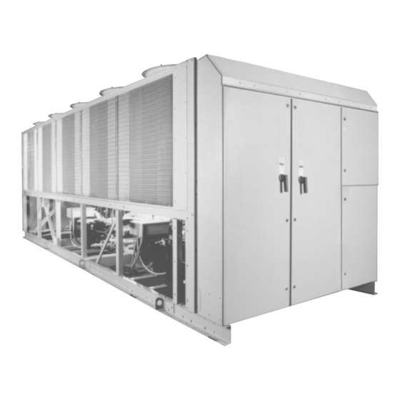
- Page 1 FORM 201.18-EG1 (200) Millennium ® Air Cooled Screw Liquid Chillers (STYLE F) 28971AR THE VAPOR APOR ® • • 200, 230, 380, 50 - 200 TONS 460, & 575 Models 80 - 420 TONS (310 - 1460 kW) 60 Hz...
-
Page 2: Table Of Contents
Typical Control Wiring – 2-Compressor Units ...94 Application Data ...96 Guide Specifications ...97 The Model Number denotes the following characteristics of the unit: YORK Chiller YC = YORK Chiller Air-Cooled Compressor Type S = Screw Nominal Capacity (tons) Unit Designator... -
Page 3: Introduction
Air Cooled Screw Liquid Chillers 28971AR YORK Millennium Air Cooled Screw Compressor machines are the state-of-the-art in air-cooled chillers, providing chilled fluids for all air conditioning applications. Completely self-contained and designed for outdoor installation, these chillers employ new, low noise, energy efficient, serviceable, semi-hermetic screw compressors designed and manufactured specifically for this new product line. -
Page 4: Specifications
Specifications These YORK air cooled chillers are shipped as a com- plete factory package. Each unit is completely as- sembled with all interconnecting refrigerant piping and internal wiring, ready for field installation: COMPLETE FACTORY PACKAGE • Each compressor is installed on its own indepen-... - Page 5 • Program – Low leaving liquid temperature cutout, 300 to 600 second anti-recycle timer, lag compressor start time delay, and average motor current unload point. Liquid temperature setpoint reset signal from YORK ISN or building automation system (by others) via: FORM 201.18-EG1...
- Page 6 40°F (22°C) reset using a: 4 to 20 milliamp, 0 to 10 VDC input, or discrete reset input. [NOTE: The Standard MicroPanel can be directly connected to a YORK ISN Build- ing Automation System via the standard on- board RS485 communication port. This Option also provides open system compatibility with other communications networks (BACNET™...
-
Page 7: Accessories And Options
Printed circuit board to accept 4 to 20 milliamp, 0 to 10 VDC, or dry contact closure input from the BAS. A YORK ISN Building Automation System can pro- vide a Pulse Width Modulated (PWM) signal di- rect to the standard control panel via the standard on-board RS485 port. - Page 8 USA (ASME, ASHRAE-15), Germany (TÜV), France (CODAP), Italy (ISPESL), and Poland (UDT) . Some available only on 50 Hz units. Consult with your YORK rep- resentative to ensure compliance with job require- ments (Factory Mounted). Flange Accessory – Consists of raised face flanges to convert grooved water nozzles to flanged cooler connections.
- Page 9 (Factory mounted.) YORK INTERNATIONAL Louvered (Condensers) / Wire (Mechanicals) – Louvered panels mounted over the exterior con-...
-
Page 10: Temperatures And Flows
1. For leaving brine temperature below 40°F (4.4°C), contact your nearest YORK office for application requirements. 2. For leaving water temperature higher than 55°F (12.8°C), contact the nearest YORK office for application guidelines. 3. The evaporator is protected against freezing to -20°F (-28.8°C) with an electric heater as standard. - Page 11 1. For leaving brine temperature below 40°F (4.4°C), contact your nearest YORK office for application requirements. 2. For leaving water temperature higher than 55°F (12.8°C), contact the nearest YORK office for application guidelines. 3. The evaporator is protected against freezing to -20°F (-28.8°C) with an electric heater as standard.
-
Page 12: Water Pressure Drop
Water Pressure Drop ENGLISH UNITS COOLER WATER PRESSURE DROP 100.0 1000.0 WATER FLOW (GPM) LD04481 MODEL NUMBER YCAS COOLER 0090, 0100, 0110, 0120, 0130, 0140 0150, 0160, 0170, 0180, 0200, 0210, 0230 0250, 0270, 0300, 0330 0360, 0400, 0440 YORK INTERNATIONAL... - Page 13 FORM 201.18-EG1 SI UNITS COOLER WATER PRESSURE DROP 1000 WATER FLOW (l/s) LD04482 MODEL NUMBER YCAS COOLER 0090, 0100, 0110, 0120, 0130, 0140 0150, 0160, 0170, 0180, 0200, 0210, 0230 0250, 0270, 0300, 0330 0360, 0400, 0440 YORK INTERNATIONAL...
-
Page 14: Ratings
105.8 109.7 10.1 102.9 117.7 107.5 110.2 10.2 104.6 118.3 109.3 110.7 10.3 106.3 118.8 112.9 111.7 10.6 109.8 119.9 116.6 112.6 10.9 113.4 120.9 120.4 113.6 11.1 117.1 122.0 10.2 126.2 115.1 11.5 122.7 123.6 10.5 YORK INTERNATIONAL 11.1 11.1 11.6... - Page 15 5. Rated in accordance with ARI Standard 550/590-98 6. Certified in accordance with the ARI Water-Chilling Packages Using the Vapor Compression Cycle Certification Program, which is based on ARI Standard 550/590. YORK INTERNATIONAL AIR TEMPERATURE ON CONDENSER (°F) kW EER TONS EER TONS kW EER TONS 70.0 110.9...
- Page 16 137.3 10.3 134.7 127.7 11.4 132.1 137.9 10.4 136.9 128.2 11.5 134.1 138.4 10.5 141.3 129.1 11.8 138.4 139.4 10.8 145.8 129.9 12.1 142.8 140.2 11.1 150.5 130.7 12.4 147.3 141.1 11.4 157.6 131.7 12.9 154.2 142.3 11.8 YORK INTERNATIONAL...
- Page 17 5. Rated in accordance with ARI Standard 550/590-98 6. Certified in accordance with the ARI Water-Chilling Packages Using the Vapor Compression Cycle Certification Program, which is based on ARI Standard 550/590. YORK INTERNATIONAL AIR TEMPERATURE ON CONDENSER (°F) kW EER TONS EER TONS kW EER TONS 97.4 153.8...
- Page 18 168.3 175.4 10.6 164.2 188.2 171.0 176.6 10.7 166.7 189.3 173.8 177.7 10.9 169.6 190.7 179.3 179.9 11.1 174.6 192.9 10.1 185.0 182.1 11.3 180.4 195.6 10.3 190.7 184.3 11.5 186.1 198.0 10.5 199.5 187.6 11.8 194.6 201.7 10.8 YORK INTERNATIONAL...
- Page 19 5. Rated in accordance with ARI Standard 550/590-98 6. Certified in accordance with the ARI Water-Chilling Packages Using the Vapor Compression Cycle Certification Program, which is based on ARI Standard 550/590. YORK INTERNATIONAL AIR TEMPERATURE ON CONDENSER (°F) kW EER TONS EER TONS kW EER TONS 7.4 123.8 205.0...
- Page 20 206.1 207.3 11.0 201.1 222.4 212.7 209.8 11.2 207.5 225.1 219.5 212.2 11.4 214.1 227.8 226.4 214.7 11.7 220.8 230.5 236.9 218.3 12.0 231.0 234.6 YORK INTERNATIONAL 10.0 10.2 10.4 10.7 11.0 10.1 10.3 10.5 10.8 10.0 10.2 10.4 10.7 11.0...
- Page 21 5. Rated in accordance with ARI Standard 550/590-98 6. Certified in accordance with the ARI Water-Chilling Packages Using the Vapor Compression Cycle Certification Program, which is based on ARI Standard 550/590. YORK INTERNATIONAL AIR TEMPERATURE ON CONDENSER (°F) kW EER TONS EER TONS kW EER TONS 7.3 152.9 258.1...
- Page 22 280.1 289.9 10.8 273.0 310.9 288.9 294.1 11.0 281.7 315.3 298.0 298.2 11.2 290.6 319.8 307.2 302.2 11.4 299.5 324.4 321.2 308.4 11.7 313.1 331.2 YORK INTERNATIONAL 10.0 10.2 10.3 10.4 10.7 10.9 11.2 11.5 10.0 10.1 10.2 10.4 10.5 10.7 11.0...
- Page 23 3. LCWT = Leaving Chilled Water Temperature 4. Ratings based on 2.4 GPM cooler water per ton 5. Rated in accordance with ARI Standard 550/590. YORK INTERNATIONAL AIR TEMPERATURE ON CONDENSER (°F) kW EER TONS EER TONS kW EER TONS 7.6 185.9 300.0...
- Page 24 375.3 391.1 10.7 363.7 417.2 387.4 397.8 10.9 375.7 424.3 399.8 404.4 11.1 387.7 431.4 412.3 411.0 11.2 399.8 438.8 431.3 421.0 11.5 418.4 449.8 YORK INTERNATIONAL 10.0 10.0 10.2 10.4 10.6 10.8 10.0 10.1 10.2 10.4 10.6 10.8 11.2 10.1 10.3...
- Page 25 3. LCWT = Leaving Chilled Water Temperature 4. Ratings based on 2.4 GPM cooler water per ton 5. Rated in accordance with ARI Standard 550/590. YORK INTERNATIONAL AIR TEMPERATURE ON CONDENSER (°F) kW EER TONS EER TONS kW EER TONS 7.3 240.1 407.9...
- Page 26 427.5 446.2 10.7 420.4 481.7 434.2 448.5 10.8 426.9 484.2 440.9 450.8 10.9 433.4 486.8 10.0 454.5 455.4 11.2 446.7 491.9 10.2 468.5 460.0 11.4 460.3 497.0 10.4 482.7 464.6 11.7 474.1 502.2 10.6 504.6 471.7 12.0 495.5 510.1 11.0 YORK INTERNATIONAL...
- Page 27 3. LCWT = Leaving Chilled Water Temperature 4. Ratings based on 2.4 GPM cooler water per ton 5. Rated in accordance with ARI Standard 550/590. YORK INTERNATIONAL AIR TEMPERATURE ON CONDENSER (°F) kW EER TONS EER TONS kW EER TONS 7.2 321.9 550.8...
- Page 28 295.5 161.4 1.7 334.9 152.1 300.5 160.9 1.7 344.9 153.4 305.6 160.5 1.7 355.1 154.7 310.7 160.2 1.8 365.5 156.1 315.8 159.9 1.8 376.0 157.5 320.9 159.7 1.8 386.7 159.0 325.0 159.0 1.9 397.6 160.5 327.0 157.6 1.9 YORK INTERNATIONAL...
- Page 29 = Chiller EER (includes power from compressors, fans, and control panel’s 0.8 KW) 3. LCWT = Leaving Chilled Water Temperature 4. Ratings based on 2.4 GPM cooler water per ton 5. Rated in accordance with ARI Standard 550/590. YORK INTERNATIONAL AIR TEMPERATURE – CONDENSER (°C) kWE COP 363.2 122.6 353.3 140.9...
- Page 30 419.1 229.2 1.7 554.2 246.0 2.1 421.8 227.8 1.7 570.8 249.2 2.2 424.3 226.4 1.8 586.8 252.4 2.2 426.8 225.0 1.8 602.7 255.2 2.2 429.3 223.7 1.8 611.8 255.3 2.3 431.6 222.4 1.8 621.9 255.6 2.3 433.5 221.0 1.8 YORK INTERNATIONAL...
- Page 31 = Chiller EER (includes power from compressors, fans, and control panel’s 0.8 KW) 3. LCWT = Leaving Chilled Water Temperature 4. Ratings based on 2.4 GPM cooler water per ton 5. Rated in accordance with ARI Standard 550/590. YORK INTERNATIONAL AIR TEMPERATURE – CONDENSER (°C) kWE COP 575.3 192.6 560.4 220.8...
- Page 32 2.1 660.9 337.5 1.8 856.6 378.8 2.1 666.6 333.8 1.9 875.5 380.2 2.2 672.2 330.2 1.9 893.5 381.4 2.2 677.6 326.7 1.9 912.6 382.9 2.3 682.9 323.4 2.0 931.9 384.6 2.3 687.9 320.1 2.0 951.3 386.3 2.3 692.8 316.9 2.1 YORK INTERNATIONAL...
- Page 33 = Chiller EER (includes power from compressors, fans, and control panel’s 0.8 KW) 3. LCWT = Leaving Chilled Water Temperature 4. Ratings based on 2.4 GPM cooler water per ton 5. Rated in accordance with ARI Standard 550/590. YORK INTERNATIONAL AIR TEMPERATURE – CONDENSER (°C) kWE COP 969.3 319.2 916.3 358.1...
- Page 34 2.5 1314.2 575.7 2.2 1037.0 509.1 1.9 2.6 1339.7 575.2 2.2 1044.9 503.5 2.0 2.6 1363.5 575.2 2.2 1052.9 498.4 2.0 2.6 1388.8 575.5 2.3 1060.2 493.3 2.0 2.7 1413.6 575.8 2.3 1067.0 488.4 2.1 kWE COP kWo kWE COP 995.4 529.3 1.8 YORK INTERNATIONAL...
- Page 35 3. LCWT = Leaving Chilled Water Temperature 4. Ratings based on 2.4 GPM cooler water per ton 5. Rated in accordance with ARI Standard 550/590. YORK INTERNATIONAL AIR TEMPERATURE – CONDENSER (°C) kWE COP 2.8 1375.9 543.0 2.4 1306.7 593.4 2.1 1017.9 516.8 1.9 2.8 1413.8 548.6 2.4 1334.7 594.7 2.1 1023.9 510.3 1.9...
-
Page 36: Physical Data
1140 1140 1140 35.4 35.4 35.4 35.4 10,575 10,575 10,575 10,575 114,400 114,400 114,400 YORK INTERNATIONAL 0170EC 164.3 5 / 5 10,694 11,960 11,358 12,624 85 / 78 Yes / No 4 / 4 2 / 1.8 1140 35.4 10,575 114,400 2 / 1.53... - Page 37 Maximum Refrigerant Side Pressure, PSIG Minimum Chilled Water Flow Rate, GPM Maximum Chilled Water Flow Rate, GPM Water Connections, inches 1 Optional 300 PSIG Waterside available YORK INTERNATIONAL ENGLISH UNITS MODEL NUMBER YCAS 0180EC 0200EC 0210EC 0230EC 0250EC 171.6 186.7 194.8...
- Page 38 19.0 19.0 19.0 53,989 53,989 53,989 53,989 10.7 11.5 11.9 37.9 37.9 47.1 47.1 YORK INTERNATIONAL 0170EC 578.0 86 / 86 19 / 19 4,850 5,424 5,152 5,726 Yes / No 23.78 4 / 4 2 / 1.8 19.0 53,989 2 / 1.53...
- Page 39 Maximum Refrigerant Side Pressure, Bar Minimum Chilled Water Flow Rate, l/sec. Maximum Chilled Water Flow Rate, l/sec. Water Connections, inches 1 Optional 21 Bar Waterside available YORK INTERNATIONAL SI UNITS MODEL NUMBER YCAS 0180EC 0200EC 0210EC 0230EC 0250EC 603.4 656.6 685.2...
-
Page 40: Dimensions
Site restrictions may compromise minimum clearances indicated below, resulting in unpre- dictable air flow patterns and possible diminished performance. YORK’s unit controls will optimize operation without nuisance high pres- sure safety cutout; however, the system designer must consider potential performance degradation. Access to the unit control center assumes the unit is no higher than on spring isolators. - Page 41 CENTER OF GRAVITY (Alum.) YCAS 0090 72.9" 0100 73.0" 23" 25" 69 3/4" 27 7/8" 15 3/4" YORK INTERNATIONAL 5/8" DIA. MOUNTING HOLES (TYP.) POWER ELEMENTS FOR SYS. 1 CONTROL/OPTIONS PANEL POWER ELEMENTS FOR SYS. 2 45 1/2" 45 1/2"...
- Page 42 Site restrictions may compromise minimum clearances indicated below, resulting in unpre- dictable air flow patterns and possible diminished performance. YORK’s unit controls will optimize operation without nuisance high pressure safety cutout; however, the system designer must consider potential performance degradation. Access to the unit control center assumes the unit is no higher than on spring isolators.
- Page 43 2235 ORIGIN CENTER OF GRAVITY (Alum.) YCAS 0090 1852.3 1057.4 902.0 0100 1855.4 1053.5 895.0 1772 YORK INTERNATIONAL 16 DIA. MOUNTING HOLES (TYP.) POWER ELEMENTS FOR SYS. 1 CONTROL/OPTIONS PANEL APPROX. OPERATING WEIGHT DISTRIBUTION POWER ELEMENTS FOR SYS. 2 1156...
- Page 44 Site restrictions may compromise minimum clearances indicated below, resulting in unpre- dictable air flow patterns and possible diminished performance. YORK’s unit controls will optimize operation without nuisance high pres- sure safety cutout; however, the system designer must consider potential performance degradation. Access to the unit control center assumes the unit is no higher than on spring isolators.
- Page 45 ORIGIN CENTER OF GRAVITY (Alum.) YCAS 0110 81.0" 0120 81.1" 23" 25" 69 3/4" 24 15/16" YORK INTERNATIONAL 5/8" DIA. MOUNTING HOLES (TYP.) POWER ELEMENTS FOR SYS. 1 CONTROL/OPTIONS PANEL POWER ELEMENTS FOR SYS. 2 55 13/16" 54 3/8" VIEW D-D...
- Page 46 Site restrictions may compromise minimum clearances indicated below, resulting in unpre- dictable air flow patterns and possible diminished performance. YORK’s unit controls will optimize operation without nuisance high pressure safety cutout; however, the system designer must consider potential performance degradation. Access to the unit control center assumes the unit is no higher than on spring isolators.
- Page 47 2235 ORIGIN CENTER OF GRAVITY (Alum.) YCAS 0110 1811.4 1093.5 877.2 0120 1814.1 1091.4 874.0 1772 YORK INTERNATIONAL 16 DIA. MOUNTING HOLES (TYP.) POWER ELEMENTS FOR SYS. 1 CONTROL/OPTIONS PANEL APPROX. OPERATING WEIGHT DISTRIBUTION POWER ELEMENTS FOR SYS. 2 1418...
- Page 48 Site restrictions may compromise minimum clearances indicated below, resulting in unpre- dictable air flow patterns and possible diminished performance. YORK’s unit controls will optimize operation without nuisance high pres- sure safety cutout; however, the system designer must consider potential performance degradation. Access to the unit control center assumes the unit is no higher than on spring isolators.
- Page 49 0160 107.0" 0170 107.0" 0180 107.0" 36" 78" 2" SYS. #1 7-1/2" POWER OPENING (BOTH SIDES) 54-1/2" 37-1/2" YORK INTERNATIONAL 5/8" DIA. MOUNTING HOLES (TYP.) 53-7/8" 53-7/8" TOP VIEW CENTER OF GRAVITY (Copper) YCAS 44.4" 37.8" 0130 103.5" 44.4" 37.8"...
- Page 50 Site restrictions may compromise minimum clearances indicated below, resulting in unpre- dictable air flow patterns and possible diminished performance. YORK’s unit controls will optimize operation without nuisance high pressure safety cutout; however, the system designer must consider potential performance degradation. Access to the unit control center assumes the unit is no higher than on spring isolators.
- Page 51 2717.8 1092.2 919.5 0170 2717.8 1092.2 919.5 0180 2717.8 1092.2 919.5 1981 SYS. #1 POWER OPENING (BOTH SIDES) 1385 YORK INTERNATIONAL 16 DIA. MOUNTING HOLES (TYP.) POWER ELEMENTS FOR SYS. #2 1368 1368 TOP VIEW CENTER OF GRAVITY (Copper) YCAS 0130 2628.9 1127.8 1033.8...
- Page 52 Site restrictions may compromise minimum clearances indicated below, resulting in unpre- dictable air flow patterns and possible diminished performance. YORK’s unit controls will optimize operation without nuisance high pressure safety cutout; however, the system designer must consider potential performance degradation. Access to the unit control center assumes the unit is no higher than on spring isolators.
- Page 53 0200 119.4" 0210 119.4" 0230 119.4" 36" 78" 2" SYS. #1 7-1/2" POWER OPENING (BOTH SIDES) 54-7/16" 37-1/2" YORK INTERNATIONAL 5/8" DIA. MOUNTING HOLES (TYP.) 65-5/16" TOP VIEW CENTER OF GRAVITY (Copper) YCAS 43.2" 38.0" 0200 122.3" 43.2" 38.0" 0210 122.3"...
- Page 54 Site restrictions may compromise minimum clearances indicated below, resulting in unpre- dictable air flow patterns and possible diminished performance. YORK’s unit controls will optimize operation without nuisance high pres- sure safety cutout; however, the system designer must consider potential performance degradation. Access to the unit control center assumes the unit is no higher than on spring isolators.
- Page 55 YCAS 0200 3032.8 1097.3 965.2 0210 3032.8 1097.3 965.2 0230 3032.8 1097.3 965.2 1981 SYS. #1 POWER OPENING (BOTH SIDES) YORK INTERNATIONAL 16 DIA. MOUNTING HOLES (TYP.) 1658 1658 TOP VIEW CENTER OF GRAVITY (Copper) YCAS 0200 3106.4 1099.8 1041.4 0210 3106.4 1099.8 1041.4...
- Page 56 Site restrictions may compromise minimum clearances indicated below, resulting in unpre- dictable air flow patterns and possible diminished performance. YORK’s unit controls will optimize operation without nuisance high pressure safety cutout; however, the system designer must consider potential performance degradation. Access to the unit control center assumes the unit is no higher than on spring isolators.
- Page 57 141.6" 0270 140.6" 36" 78" 2" SYS. #1 & #2 POWER OPENING 7-1/2" (BOTH SIDES) HOLES (EACH SIDE) 68" YORK INTERNATIONAL 57-3/16" 57-3/16" TOP VIEW CENTER OF GRAVITY (Copper) YCAS 41.6" 33.8" 0250 145.4" 41.7" 33.7" 0270 144.5" SYS. #3 10"...
- Page 58 Site restrictions may compromise minimum clearances indicated below, resulting in unpre- dictable air flow patterns and possible diminished performance. YORK’s unit controls will optimize operation without nuisance high pres- sure safety cutout; however, the system designer must consider potential performance degradation. Access to the unit control center assumes the unit is no higher than on spring isolators.
- Page 59 CENTER OF GRAVITY (Alum.) YCAS 0250 3597 0270 3572 1981 SYS. #1 & #2 POWER OPENING (BOTH SIDES) HOLES (EACH SIDE) 1727 YORK INTERNATIONAL 16 DIA. MOUNTING HOLES (TYP.) 1453 1453 TOP VIEW CENTER OF GRAVITY (Copper) YCAS 1057 0250 3693...
- Page 60 Site restrictions may compromise minimum clearances indicated below, resulting in unpre- dictable air flow patterns and possible diminished performance. YORK’s unit controls will optimize operation without nuisance high pressure safety cutout; however, the system designer must consider potential performance degradation. Access to the unit control center assumes the unit is no higher than on spring isolators.
- Page 61 36" 78" 2" SYS. #1 & #2 POWER OPENING 7-1/2" (4) 2-1/4" DIA. RIGGING (BOTH SIDES) HOLES (EACH SIDE) 146" 68" YORK INTERNATIONAL 56-5/16" 57-3/16" 57-3/16" TOP VIEW CENTER OF GRAVITY (Copper) YCAS 41.6" 34.8" 0300 159.2" 41.7" 34.5" 0330 156.8"...
- Page 62 Site restrictions may compromise minimum clearances indicated below, resulting in unpre- dictable air flow patterns and possible diminished performance. YORK’s unit controls will optimize operation without nuisance high pres- sure safety cutout; however, the system designer must consider potential performance degradation. Access to the unit control center assumes the unit is no higher than on spring isolators.
- Page 63 YCAS 0300 3911 0330 3842 1981 SYS. #1 & #2 (4) 57 DIA. RIGGING POWER OPENING HOLES (EACH SIDE) (BOTH SIDES) 3708 1727 YORK INTERNATIONAL 1453 1453 TOP VIEW CENTER OF GRAVITY (Copper) YCAS 1057 0300 4045 1058 0330 3982 SYS.
- Page 64 Site restrictions may compromise minimum clearances indicated below, resulting in unpre- dictable air flow patterns and possible diminished performance. YORK’s unit controls will optimize operation without nuisance high pressure safety cutout; however, the system designer must consider potential performance degradation. Access to the unit control center assumes the unit is no higher than on spring isolators.
- Page 65 78" 2" SYS. #1 & #2 7-1/2" POWER OPENING (4) 2-1/4" DIA. RIGGING (BOTH SIDES) HOLES (EACH SIDE) 68" 89-11/16" YORK INTERNATIONAL 36-5/16" 57-3/16" 56" TOP VIEW CENTER OF GRAVITY (Copper) YCAS 44.0" 33.2" 0360 200.7" SYS. #3 & #4 262-3/4"...
- Page 66 Site restrictions may compromise minimum clearances indicated below, resulting in unpre- dictable air flow patterns and possible diminished performance. YORK’s unit controls will optimize operation without nuisance high pres- sure safety cutout; however, the system designer must consider potential performance degradation. Access to the unit control center assumes the unit is no higher than on spring isolators.
- Page 67 ORIGIN CENTER OF GRAVITY (Alum.) YCAS 0360 5011 1981 (4) 57 DIA. RIGGING POWER OPENING HOLES (EACH SIDE) (BOTH SIDES) 1727 2277 YORK INTERNATIONAL 1453 1453 TOP VIEW CENTER OF GRAVITY (Copper) YCAS 1117 0360 5097 6673 1713 11132 SIDE VIEW FORM 201.18-EG1...
- Page 68 Site restrictions may compromise minimum clearances indicated below, resulting in unpre- dictable air flow patterns and possible diminished performance. YORK’s unit controls will optimize operation without nuisance high pressure safety cutout; however, the system designer must consider potential performance degradation. Access to the unit control center assumes the unit is no higher than on spring isolators.
- Page 69 36" 78" 2" SYS. #1 & #2 7-1/2" POWER OPENING (4) 2-1/4" DIA. RIGGING (BOTH SIDES) HOLES (EACH SIDE) 310-3/4" 68" 89-11/16" YORK INTERNATIONAL 84-5/16" 57-3/16" TOP VIEW CENTER OF GRAVITY (Copper) YCAS 44.0" 34.1" 0400 222.5" 0440 219.0" "...
- Page 70 Site restrictions may compromise minimum clearances indicated below, resulting in unpre- dictable air flow patterns and possible diminished performance. YORK’s unit controls will optimize operation without nuisance high pres- sure safety cutout; however, the system designer must consider potential performance degradation. Access to the unit control center assumes the unit is no higher than on spring isolators.
- Page 71 0400 5556 0440 5459 1981 SYS. #1 & #2 POWER OPENING (4) 57 DIA. RIGGING (BOTH SIDES) HOLES (EACH SIDE) 1727 2277 YORK INTERNATIONAL 1453 2142 TOP VIEW CENTER OF GRAVITY (Copper) YCAS 1117 0400 5650 1117 0440 5563 SYS. #3 & #4...
- Page 72 816.4 1.02 25.9 Green 2200 997.9 0.83 21.0 Gray 2600 1179.3 0.74 18.7 White 3000 1360.8 0.70 17.7 Gold YORK INTERNATIONAL TOTAL 7,552 7,660 8,554 8,608 10,315 10,537 11,263 11,247 11,358 11,358 12,513 12,634 12,745 17,334 17,531 18,896 19,251 24,191...
- Page 73 -1-532 -1-531 0360 -1-551 -1-553 -1-553 -1-532 -2-520 -1-553 0400 -1-551 -1-553 -1-553 -2-521 -2-520 -1-553 0440 -1-551 -1-553 -1-553 -2-521 -2-520 -1-553 YORK INTERNATIONAL Aluminum Fin Coils –– –– –– –– –– –– –– –– –– –– –– ––...
- Page 74 –– –– –– 5,726 –– –– –– –– –– 5,776 –– –– –– –– –– 6,398 –– –– –– –– –– 6,448 –– –– –– –– –– 6,499 8,725 8,814 9,576 9,737 1,030 12,121 1,080 12,887 1,082 13,107 YORK INTERNATIONAL...
- Page 75 0330 -1-551 -1-553 -2-531 -2-53 -1-532 -1-532 0360 -1-551 -1-553 -1-553 -1-532 -2-520 -2-530 0400 -1-552 -1-553 -1-553 -2-53 -2-521 -2-531 0440 -1-552 -1-553 -1-553 -2-53 -2-521 -2-531 YORK INTERNATIONAL Copper Fin Coils — — — — — — — — —...
-
Page 76: Isolator Details
R-4 or RD-4 (158.7) LD04033 LD04737 3.375" 2.875" 2.5" 0.5" (85.8) (73.2) (63.5) (12.7) 4.625" 2.75" 3.0" 0.5" (117.6) (69.8) (76.2) (12.7) R4 / RD4 SERIES LD04805 LD04804 4.125" 0.563" 0.25" (104.8) (14.4) (6.3) 5.0" 0.563" 0.375" (127.0) (14.4) (9.6) YORK INTERNATIONAL... - Page 77 AWMR-1-XXX DIMENSIONS – (In.) AWMR-1 10-1/2 50-553 11NC AWMR-2 50-553 10NC YORK INTERNATIONAL CP-2-XX LD02973 3-1/2 1-3/4 7-1/2 3-3/4 FORM 201.18-EG1 LD01089 AWMR-2-XXX 8-1/2 4-1/4 10-1/2 9-1/2 14-1/2 7-1/4 LD02974...
-
Page 78: Electrical Data
2045 33.0 1093 23.0 19.0 15.2 2256 38.0 2045 33.0 1093 23.0 19.0 15.2 2256 38.0 2045 33.0 1093 23.0 19.0 15.2 2256 38.0 2045 33.0 1093 23.0 19.0 15.2 2256 38.0 2045 33.0 1093 23.0 19.0 15.2 YORK INTERNATIONAL... - Page 79 0120EC 0130EC 0140EC 0150EC 0160EC 0170EC 0180EC 0200EC 0210EC 0230EC YORK INTERNATIONAL SYSTEM #2 FIELD-SUPPLIED WIRING FACTORY PROVIDED (LUGS) WIRE RANGE STD. TERMINAL OPT. NF. OPT. C.B. BLOCK DISC SW. # 2 - 300 # 6 - 350 250 - 500...
- Page 80 COMPRESSOR #3 DATA 1,093 1,093 23.0 19.0 15.2 1,093 1,093 23.0 19.0 15.2 1,093 1,093 23.0 19.0 15.2 1,093 1,093 23.0 19.0 15.2 1,093 1,093 23.0 19.0 15.2 1,093 1,093 23.0 19.0 15.2 1,093 1,093 23.0 19.0 15.2 YORK INTERNATIONAL...
- Page 81 3, 5 MAX. 0250EC 0270EC 0300EC 0330EC 0360EC 0400EC 0440EC YORK INTERNATIONAL ELECTRICAL SYSTEM #2 FIELD SUPPLIED WIRING FACTORY PROVIDED (LUGS) COMPRESSOR #2 WIRE RANGE STANDARD OPTIONAL NF RLA Y- LRA X-LRA RLA Y- LRA X-LRA QTY FLA(EA) LRA(EA) 4, 6 TERMINAL BLOCK DISC.
- Page 82 (3) 2/0-400 (2) 250-500 (2) 3/0-250 (2) 3/0-250 (4) 4/0-500 (3) 2/0-400 (2) 250-500 (2) 3/0-250 (2) 3/0-250 (4) 4/0-500 (4) 4/0-500 (2) 250-500 (2) 250-500 (2) 3/0-250 (4) 4/0-500 (4) 4/0-500 (2) 250-500 (2) 250-500 (2) 3/0-250 YORK INTERNATIONAL...
- Page 83 298.0 0200EC 181.0 149.0 119.0 374.0 325.0 0210EC 197.0 163.0 130.0 374.0 325.0 0230EC 197.0 163.0 130.0 YORK INTERNATIONAL SYSTEM #1 FAN DATA 11, 12 COMPRESSOR DATA X-LRA (EA.) (EA) 1257 38.0 159.0 1103 33.0 138.0 23.0 84.0 19.0 70.0 15.2...
- Page 84 (3) 2/0-250 (3) 2/0-400 (2) 250-500 (2) 250-500 (3) 2/0-400 (2) 250-500 (2) 250-500 (3) 2/0-400 (3) 2/0-400 (2) 250-500 (4) 4/0-500 (3) 2/0-400 (2) 250-500 (4) 4/0-500 (4) 4/0-500 (3) 2/0-400 (4) 4/0-500 (4) 4/0-500 (3 )2/0-400 YORK INTERNATIONAL...
- Page 85 1,093 1,093 1,093 1,093 1,093 1,093 1,093 1,093 1,093 1,093 1,093 1,093 1,093 YORK INTERNATIONAL ELECTRICAL SYSTEM #2 FIELD SUPPLIED WIRING 11, 12 FAN DATA COMPRESSOR #2 DATA RLA Y- LRA X-LRA 23.0 1,093 19.0 15.2 23.0 1,093 19.0 15.2 23.0...
- Page 86 # 6 - 350 (2) 3/0-250 # 6 - 350 (2) 3/0-250 (2) 3/0-250 (2) 3/0-250 (2) 3/0-250 (2) 3/0-250 (2) 3/0-250 (2) 3/0-250 (2) 3/0-250 (2) 3/0-250 (2) 3/0-250 (2) 250-500 (2) 3/0-250 (2) 250-500 (2) 3/0-250 YORK INTERNATIONAL...
- Page 87 COMPRESSOR DATA VOLTS YCAS X-LRA 0090EC 0100EC 0110EC 0120EC 0130EC 0140EC 0150EC 0160EC 0170EC 0180EC 0200EC 0210EC 0230EC YORK INTERNATIONAL SYSTEM #1 FAN DATA 11, 12 COMPRESSOR DATA (EA.) (EA) 23.0 19.0 15.2 23.0 19.0 15.2 21.0 27.0 26.0 21.0 27.0...
-
Page 88: Electrical Notes
19.0 15.2 19.0 15.2 19.0 15.2 19.0 15.2 VOLTAGE CODE -17 = 200-3-60 -28 = 230-3-60 -40 = 380-3-60 -46 = 460-3-60 -58 = 575-3-60 YORK INTERNATIONAL 23.0 19.0 15.2 23.0 19.0 15.2 21.0 27.0 26.0 21.0 27.0 26.0 19.0 15.2... - Page 89 11. Consult factory for Electrical Data on units equipped with “High Static Fan” option. High Static Fans are 3.8 kW each. 12. FLA for “Low Noise Fan” motors: 200V = 8.0A, 230V = 7.8A, 380V = 4.4A, 460V = 3.6A, 575V = 2.9A. 13. Group Rated breaker must be HACR type for cUL Machines. YORK INTERNATIONAL (Continued) POWER...
-
Page 90: Power Connection Options
FIG. 2 – OPTIONAL SINGLE-POINT POWER SUPPLY WITH INDIVIDUAL SYSTEM CIRCUIT BREAKERS Optional Field Provided 115-1-60 Micropanel Supply Suitable for Y- Start and Across-The-Line Start See Note 3 LD05548 Optional Field Provided 115-1-60 Micropanel Supply Suitable for Y- Start and Across-The-Line Start See Note 3 LD05549 YORK INTERNATIONAL... - Page 91 FIG. 3 – OPTIONAL SINGLE-POINT POWER SUPPLY CONNECTION WITH FIELD SUPPLIED CIRCUIT PROTECTION See page 93 for notes. FIG. 4 – OPTIONAL SINGLE-POINT POWER SUPPLY WIRING TO FACTORY CIRCUIT BREAKER YORK INTERNATIONAL Optional Field Provided 115-1-60 Micropanel Supply Suitable for:...
- Page 92 The Two Compressor Diagrams Field Supply #2 See Note 3 Field Supply #1 LD05552 Suitable for: Start and Across the Line Start Control Panel Wiring as shown on The Two-Compressor Diagrams Field Supply #2 See Note 3 Field Supply #1 YORK INTERNATIONAL...
- Page 93 Transient Voltage Suppression Terminal Block for Customer Connections Terminal Block for Customer Low Voltage (Class 2) Connections. See Note 2 Terminal Block for YORK Connections Only Wiring and Components by YORK Optional Equipment Wiring and/or Components by Others FORM 201.18-EG1...
-
Page 94: Typical Control Wiring – 2-Compressor Units
Typical Control Wiring – 2-Compressor Units YORK INTERNATIONAL... - Page 95 FORM 201.18-EG1 REFER TO BOTTOM OF PAGE 93 FOR LEGEND. YORK INTERNATIONAL...
-
Page 96: Application Data
A flow switch is available as an accessory on all units. A flow switch must be installed in the leaving water piping of the cooler and must not be used to start and stop the unit. YORK INTERNATIONAL... -
Page 97: Guide Specifications
Manufac- turer. B. Unit shall be stored and handled per Manufacturer’s instructions. YORK INTERNATIONAL PART 2 — PRODUCTS 2.01 CHILLER MATERIALS AND COMPONENTS A. General: Install and commission, as shown on the... - Page 98 (auto or manual), and maximum EMS- PWM reset temperature range. YORK INTERNATIONAL...
- Page 99 2.07 ACCESSORIES and OPTIONS Some accessories and options supercede standard product features. Your YORK representative will be pleased to provide assistance. A. Microprocessor controlled, Factory installed Wye- Delta compressor motor starters for reduced com- pressor inrush start current.
- Page 100 0.4 inches of water (100Pa) external static pressure at nominal condenser air flow. J. Microprocessor Membrane Keypad Graphics on in lieu of Standard English: 1. French language. 2. German language. 3. Spanish language. 4. Italian Language. YORK INTERNATIONAL...
- Page 101 2. 1 Inch Deflection Spring Isolators: Level adjust- able, spring and cage type isolators for mounting under the unit base rails. YORK INTERNATIONAL 3. 2 Inch Deflection Seismic Isolators: Level adjust- able, restrained mounts in rugged welded steel housing with vertical and horizontal limit stops.
- Page 102 This page intentionally left blank. YORK INTERNATIONAL...
- Page 103 FORM 201.18-EG1 This page intentionally left blank. YORK INTERNATIONAL...
- Page 104 P.O. Box 1592, York, Pennsylvania USA 17405-1592 Copyright © by York International Corporation 2000 Form 201.18-EG1 (200) Supersedes: 201.18-EG1 (999) 201.18-EG1 (399) (717) 771-7890 Subject to change without notice. Printed in USA www.york.com Proud Sponsor of the 2000 U.S. Olympic Team...