
Related Manuals for Nortel BayStack 350 Series


Summary of Contents for Nortel BayStack 350 Series
- Page 1 Software Release V3.0.0 Part No. 893-00992-E January 2000 4401 Great America Parkway Santa Clara, CA 95054 Using the BayStack 350 Series 10/100 Autosense Switch...
- Page 2 Nortel Networks NA Inc. does not assume any liability that may occur due to the use or application of the product(s) or circuit layout(s) described herein.
- Page 3 EC Declaration of Conformity This product conforms (or these products conform) to the provisions of Council Directive 89/336/EEC and 73/23/EEC. The Declaration of Conformity is available on the Nortel Networks World Wide Web site at http://libra2.corpwest.baynetworks.com/cgi-bin/ndCGI.exe/DocView/. Japan/Nippon Requirements Only Voluntary Control Council for Interference (VCCI) Statement...
- Page 4 Software is provided will be free from defects in materials and workmanship under normal use for a period of 90 days from the date Software is first shipped to Licensee. Nortel Networks will replace defective media at no charge if it is returned to Nortel Networks during the warranty period along with proof of the date of shipment.
- Page 5 Licensee will immediately destroy or return to Nortel Networks the Software, user manuals, and all copies. Nortel Networks is not liable to Licensee for damages in any form solely by reason of the termination of this license. 8. Export and Re-export. Licensee agrees not to export, directly or indirectly, the Software or related technical data or information without first obtaining any required export licenses or other governmental approvals.
-
Page 7: Table Of Contents
Contents Preface Audience ..........................xix Organization ........................xix Text Conventions ......................xxi Special Message Formats ..................xxii Acronyms ........................xxii Related Publications ...................... xxiii How to Get Help ......................xxiv Safety Messages Safety Alert Message Format ..................xxv Safety Alert Messages Used in This Guide ..............xxvii Chapter 1 Getting Started Hardware ........................1-1... - Page 8 Network Configuration ....................1-13 Power Workgroups ....................1-14 Power Workgroups and Shared Media Hub ............1-15 VLAN Workgroups ....................1-16 VLAN Configuration Screen Examples ............1-20 Additional Tips About Configuring VLANs ............1-23 MultiLink Trunks .....................1-24 Inter-Switch Trunk Configuration ..............1-24 Server Trunk Configuration ................1-26 Client/Server Configuration Utilizing MultiLink Trunks ........1-27 Trunk Configuration Screen Examples ............1-29 Before Configuring Trunks ................1-40 MultiLink Trunking Configuration Rules ............1-41...
- Page 9 Installing on a Table or Shelf ................2-7 Wall Mounting ......................2-8 Before You Begin ....................2-8 Wall Mounting the Model 350F and Model 350T ..........2-9 Rack Mounting .......................2-10 Connecting Port Cables ....................2-13 RJ-45 Port Cables ....................2-13 100BASE-FX Port Cables ..................2-14 Connecting Power ......................2-15 Verifying the Installation ....................2-16 Chapter 3 Using the Console Interface...
- Page 10 MAC Address Security Configuration ..............3-28 MAC Address Security Table ................3-31 Accelerator Keys for Repetitive Tasks ..............3-32 VLAN Configuration ....................3-34 Port Configuration ....................3-36 MultiLink Trunk Configuration .................3-39 Inter-Switch Trunk Configuration ..............3-41 Server Trunk Configuration ................3-43 Trunk Utilization ....................3-45 Port Mirroring Configuration ...................3-48 Rate Limiting Configuration ..................3-51 Port Statistics ......................3-54 Console/Service Port Configuration ................3-58...
- Page 11 Appendix A Technical Specifications Environmental ........................ A-1 Electrical ........................A-1 Physical Dimensions ...................... A-2 Performance Specifications ................... A-2 Network Protocol and Standards Compatibility ............. A-2 Data Rate ........................A-2 Interface Options ......................A-3 Safety Agency Certification ................... A-3 Electromagnetic Emissions ................... A-3 Electromagnetic Susceptibility ..................
- Page 13 Figures Figure 1-1. BayStack 350 Series Autosense Switch ..........1-1 Figure 1-2. Front-panel components ................1-2 Figure 1-3. Back-panel components ................1-4 Figure 1-4. BayStack 350 Switch Security Feature ............1-8 Figure 1-5. Configuring power workgroups ..............1-14 Figure 1-6. Configuring power workgroups and a shared media hub ......1-15 Figure 1-7.
- Page 14 Figure 1-30. Port-based mirroring configuration example ..........1-47 Figure 1-31. Port Mirroring port-based screen example ..........1-48 Figure 1-32. Address-based mirroring configuration example ........1-49 Figure 1-33. Port Mirroring address-based screen example ........1-50 Figure 1-34. Installation flowchart ................1-52 Figure 2-1. Package contents ..................2-2 Figure 2-2.
- Page 15 Figure 3-21. Trunk Utilization screen (2 of 2) .............3-46 Figure 3-22. Port Mirroring Configuration screen ............3-48 Figure 3-23. Model 350F-HD Rate Limiting Configuration screen (1 of 2) ....3-51 Figure 3-24. Model 350F-HD Rate Limiting Configuration screen (2 of 2) ....3-52 Figure 3-25.
- Page 17 Tables Table 1-1. Front-panel components ................1-3 Table 1-2. Back-panel components ................1-4 Table 2-1. Power-up sequence ................2-16 Table 3-1. Console interface main menu commands ..........3-7 Table 3-2. IP Configuration screen fields ..............3-11 Table 3-3. SNMP Configuration Menu Screen Options ..........3-15 Table 3-4. SNMP Configuration screen fields ............3-17 Table 3-5.
- Page 18 Table 3-27. Spanning Tree Port Configuration screen fields ........3-64 Table 3-28. Spanning Tree Switch Settings parameters ...........3-66 Table 3-29. TELNET Configuration screen fields ............3-69 Table 3-30. Software Download screen fields ............3-72 Table 3-31. LED indications during the software download process ......3-73 Table 3-32.
-
Page 19: Preface
BayStack 10/100 Switch line of communications products. ™ There are four versions of the BayStack 350 Series 10/100 Autosense Switch: the Model 350F-HD, the Model 350F, the Model 350T-HD, and the Model 350T. This guide describes the features, uses, and installation procedures for the four models. - Page 20 Using the BayStack 350 Series 10/100 Autosense Switch If you want to: Go to: Connect to the BayStack 350 switch Console/Service Port and Chapter 3 learn how to use the console interface (CI) menus to configure and manage the switch...
-
Page 21: Text Conventions
Preface Text Conventions This guide uses the following text conventions: bold text Indicates command names and options and text that you need to enter. Example: Enter show ip {alerts routes}. Example: Use the command. dinfo italic text Indicates file and directory names, new terms, book titles, and variables in command syntax descriptions. -
Page 22: Special Message Formats
Using the BayStack 350 Series 10/100 Autosense Switch Special Message Formats This guide uses the following formats to highlight special messages: Note: A note is used to highlight information of importance or special interest. Caution: A caution alerts the user to some action or set of conditions that could result in damage to the equipment. -
Page 23: Related Publications
Bay Networks Guide to Implementing BaySecure LAN Access for Ethernet (Part number 345-1106A) Describes Nortel Networks realtime security system that safeguards Ethernet networks from unauthorized surveillance and intrusion. You can print selected technical manuals and release notes free, directly from the Internet. -
Page 24: How To Get Help
Using the BayStack 350 Series 10/100 Autosense Switch How to Get Help If you purchased a service contract for your Nortel Networks product from a distributor or authorized reseller, contact the technical support staff for that distributor or reseller for assistance. -
Page 25: Safety Messages
Safety Messages Übersetzter Sicherheitshinweis Traduction des Messages de Sécurité Traducción de los mensajes de seguridad Messaggi relativi alla sicurezza This section translates the safety alert messages used in this guide. Safety alert messages notify users of unsafe actions or conditions that could lead to personal injury or equipment damage. - Page 26 Using the BayStack 350 Series 10/100 Autosense Switch Symbol Meaning (English, German, French, Spanish, Italian, Japanese) Vorsicht: Dieser Sicherheitshinweis macht den Benutzer auf Maßnahmen oder Bedingungen aufmerksam, die die Verletzung von Personen zur Folge haben können. Achtung: Dieser Sicherheitshinweis macht den Benutzer auf Maßnahmen oder Bedingungen aufmerksam, die eine Beschädigung der Geräte zur Folge...
-
Page 27: Safety Alert Messages Used In This Guide
Safety Messages Safety Alert Messages Used in This Guide The following safety alert messages are used in this guide. Please read and follow these instructions when you encounter them in the text. Class A Product Copyright page Caution: This device is a Class A product. In a domestic environment, this device can cause radio interference, in which case, the user may be required to take appropriate measures. - Page 28 Using the BayStack 350 Series 10/100 Autosense Switch Accumulated Weight (Wall Mount) Page 2-1 Caution: The screws and wall composition must be able to withstand the weight of the device, plus the additional weight of the attached network cables and power cords.
- Page 29 Safety Messages Accumulated Weight (Shelf or Table Mount) Page 2-3 Caution: When this device is installed in a stack on a shelf or tabletop, the accumulated weight of the port cables increases with the height of the shelf or tabletop. Achtung: Wenn dieses Gerät in einem Stapel auf einem Tisch oder einem Regalboden installiert wird, erhöht sich das Gesamtgewicht der Schnittstellenkabel mit der Höhe des Regalbodens oder Tisches.
- Page 30 Using the BayStack 350 Series 10/100 Autosense Switch Hazardous Electrical Current Page 2-5 Warning: To avoid bodily injury from hazardous electrical current, do not connect the power cord until instructed to do so. Vorsicht: Um Verletzungsgefahr durch einen elektrischen Stromschlag auszuschließen, schließen Sie das Netzstromkabel erst an, wenn Sie dazu...
- Page 31 Safety Messages Stacking Units in a Rack Page 2-10 Caution: When mounting this device in a rack, do not stack units directly on top of one another in the rack. Each unit must be secured to the rack with appropriate mounting brackets. Mounting brackets are not designed to support multiple units.
- Page 32 Using the BayStack 350 Series 10/100 Autosense Switch Hazardous Light Source Page 2-14 Warning: Fiber optic equipment can emit laser or infrared light that can injure your eyes. Never look into an optical fiber or connector port. Always assume that fiber optic cables are connected to a light source.
- Page 33 Safety Messages Turning Off Power to the Unit Page 2-15 Warning: Removal of the power cord is the only way to turn off power to this device. The power cord must always be connected in a location that can be accessed quickly and safely in case of an emergency.
- Page 34 Using the BayStack 350 Series 10/100 Autosense Switch Reset to Default Settings Command Page 3-9 Caution: If you choose the Reset to Default Settings command, all of your configured settings will be replaced with factory default settings when you press [Enter].
- Page 35 Safety Messages Choosing a Baud Rate Page 3-59 Caution: If you choose a baud rate that does not match your console terminal baud rate, you will lose communication with the configuration interface when you press [Enter]. If communication is lost, set your console terminal to match the new service port setting.
- Page 36 Using the BayStack 350 Series 10/100 Autosense Switch Changing Passwords Page 3-60 Caution: If you change the system-supplied default passwords, be sure to write the new passwords down and keep them in a safe place. If you forget the new passwords, you cannot access the console interface. In that case, contact Bay Networks for help.
- Page 37 Safety Messages Interrupting a Software Download Page 3-71 Caution: Do not interrupt power to the device during the software download process. If the power is interrupted, the firmware image can become corrupted. Achtung: Unterbrechen Sie die Stromzufuhr zum Gerät nicht, während die Software heruntergeladen wird.
- Page 38 Using the BayStack 350 Series 10/100 Autosense Switch Removing the Top Cover Page 4-1 Warning: To avoid bodily injury from hazardous electrical current, never remove the top cover of the device. There are no user-serviceable components inside. Vorsicht: Um Verletzungsgefahr durch einen elektrischen Stromschlag auszuschließen, nehmen Sie niemals die obere Abdeckung vom Gerät ab.
-
Page 39: Getting Started
Chapter 1 Getting Started This chapter introduces the BayStack 350 Series 10/100 Autosense Switch and provides network configuration examples. It also describes the Quick-Start procedures, which allow you to quickly set up parameters to manage the switch using the Simple Network Management Protocol (SNMP) or the console/service port. -
Page 40: Front-Panel Components
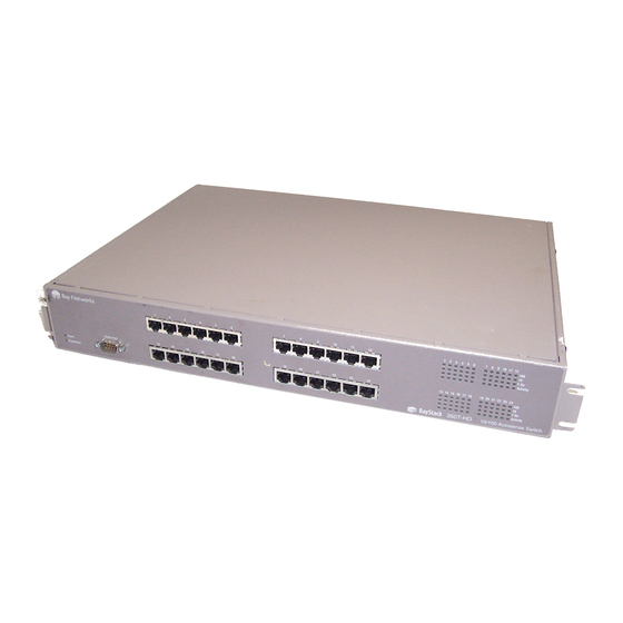
Using the BayStack 350 Series 10/100 Autosense Switch Front-Panel Components This section describes the front-panel components of the BayStack 350 switches (Figure 1-2). For a description of each numbered component, see Table 1-1. • The Model 350F-HD provides 24 autosense 10/100BASE-TX ports and two 100BASE-FX fiber optic ports. - Page 41 Getting Started Table 1-1. Front-panel components Item Icon/Label Description Power Power LED (green): On: DC power is available to the switch’s internal circuitry. Diagnostics Diagnostics LED (green): On: The switch passed the self-test. Blinking: A nonfatal error occurred during the self-test. Off: The switch failed the self-test.
-
Page 42: Back-Panel Components
Using the BayStack 350 Series 10/100 Autosense Switch Back-Panel Components This section describes the back-panel components of the BayStack 350 switches (Figure 1-3). • The console/service port for the Model 350F-HD and Model 350T-HD is located on the front panel (see “Front-Panel... -
Page 43: Cooling Fans
Getting Started Cooling Fans Variable-speed cooling fans in the BayStack 350 switch provide cooling for the internal components. When you install the switch, be sure to allow enough space on both sides of the switch for adequate air flow. Features BayStack 350 switches provide wire-speed, 100BASE-TX/100BASE-FX (Fast Ethernet) switching that allows high-performance, low-cost connections to full-duplex and half-duplex 10 Mb/s and 100 Mb/s Ethernet local area networks... - Page 44 Using the BayStack 350 Series 10/100 Autosense Switch • Configuration File download/upload support: Allows you to store your switch configuration parameters on a TFTP server. You can retrieve the configuration parameters for automatically configuring a replacement switch or other switches.
- Page 45 Getting Started • MultiLink Trunking -- Inter-switch trunks -- Server based trunks • Remote monitoring (RMON), with four groups integrated: -- Statistics -- History -- Alarms -- Events • Port-based virtual LANs (VLANs) • Port Mirroring -- Port-based -- MAC address-based •...
-
Page 46: Security
Using the BayStack 350 Series 10/100 Autosense Switch Security Your BayStack 350 switch security feature can provide three levels of security for your local area network (LAN): • MAC address-based security -- Limits access to the switch based on allowed source MAC addresses. -
Page 47: Mac Address-Based Security
LAN Access for Ethernet, a real-time security system that safeguards Ethernet networks from unauthorized surveillance and intrusion. To learn more about the Nortel Networks BaySecure LAN Access for Ethernet, refer to the Bay Networks Guide to Implementing BaySecure LAN Access for Ethernet (Part number 345-1106A). -
Page 48: Autosensing
Using the BayStack 350 Series 10/100 Autosense Switch Autosensing BayStack 350 switches are autosensing and autonegotiating devices. The term autosense refers to a port’s ability to sense the speed of an attached device. The term autonegotiation refers to a standardized protocol (IEEE 802.3u) that exists between two IEEE 802.3u-capable devices. -
Page 49: Port Mirroring
You can specify port-based monitoring, where all traffic on specified ports is monitored, or address-based monitoring, where traffic between specified MAC addresses is monitored. You can attach a probe device (such as a Nortel Networks StackProbe , or ™ equivalent) to the designated monitor port. The designated port can monitor all traffic on the network segment connected to the mirrored port. -
Page 50: Bootp Automatic Ip Configuration
Using the BayStack 350 Series 10/100 Autosense Switch BootP Automatic IP Configuration The BayStack 350 switch has a unique 48-bit hardware address, or MAC address, that is printed on a label on the back panel. You use this MAC address when you configure the network BootP server to recognize the BayStack 350 switch BootP requests. -
Page 51: Configuration And Switch Management
Configuration and Switch Management The BayStack 350 switch is shipped directly from the factory ready to operate in any 10BASE-T or 100BASE-TX standard network. You can manage the switch using the Nortel Networks Optivity network management software or any ®... -
Page 52: Power Workgroups
Using the BayStack 350 Series 10/100 Autosense Switch Power Workgroups Figure 1-5 shows BayStack 350 switches connecting dedicated power workgroups and standard departmental users. In this example, all users have access to 10 Mb/s bandwidth or 100 Mb/s bandwidth on any port. -
Page 53: Power Workgroups And Shared Media Hub
Getting Started Power Workgroups and Shared Media Hub Figure 1-6 shows power workgroups connected to servers through BayStack 350 switches in a small network. Network managers who do not want to provide each end station with the full 100 Mb/s bandwidth can designate a certain number of users that share the full bandwidth provided by one of the switch ports. -
Page 54: Vlan Workgroups
Figure 1-7. Port-based VLAN example This same type of segmentation can be extended to multiple switches across the network. Because BayStack 350 Series switches implement port-based VLANs, extending VLANs to another switch requires utilizing a single switch port for each VLAN (Figure 1-8). - Page 55 Getting Started In this example configuration (Figure 1-8), spanning tree participation must be set to Disabled because the spanning tree protocol (STP) is not supported across multiple VLANs (see “Spanning Tree Port Configuration” on page 3-63). VLAN 2 VLAN 1 9 10 11 12 F Dx F Dx...
-
Page 56: Figure 1-9. Multiple Vlans Sharing Resources
Using the BayStack 350 Series 10/100 Autosense Switch There are limitations when configuring multiple VLANs on a port and when configuring VLANs that cross multiple switches. For example, to have multiple VLANs that span multiple switches, no port should be configured to exist in more than one VLAN in any of the switches. -
Page 57: Figure 1-10. Vlan Configuration Spanning Multiple Baystack 350 Switches
Getting Started As shown in Figure 1-10, switch SW1 is configured with multiple VLANs: ports 7, 15, and 16 are in VLAN V1; ports 2, 4, 10, and 14 are in VLAN V2; and ports 1, 11, and 12 are in VLAN V1+V2. BayStack 350T switch (VLAN V1 + V2) BayStack 350T switch (VLAN V1) -
Page 58: Vlan Configuration Screen Examples
Using the BayStack 350 Series 10/100 Autosense Switch Although switch SW4 is shown with all ports configured in VLAN V1+V2, any of the ports can be assigned to additional VLANs as long as they are all in the same VLAN membership as the connecting port (port 1). -
Page 59: Figure 1-12. Vlan Configuration Screen For Switch Sw2
Getting Started VLAN Configuration Port Trunk ---- ----- ----- ----- ----- ----- ----- ----- ----- ----- [ X ] [ X ] [ X ] [ X ] [ X ] Use space bar to display choices, press <Return> or <Enter> to select choice. Press Ctrl-R to return to previous menu. -
Page 60: Figure 1-13. Vlan Configuration Screen For Switch Sw3
Using the BayStack 350 Series 10/100 Autosense Switch VLAN Configuration Port Trunk ---- ----- ----- ----- ----- ----- ----- ----- ----- ----- [ X ] [ X ] [ X ] [ X ] [ X ] [ X ] Use space bar to display choices, press <Return>... -
Page 61: Additional Tips About Configuring Vlans
Getting Started VLAN Configuration Port Trunk ---- ----- ----- ----- ----- ----- ----- ----- ----- ----- [ X ] [ X ] [ X ] [ X ] [ X ] [ X ] [ X ] [ X ] Use space bar to display choices, press <Return>... -
Page 62: Multilink Trunks
Using the BayStack 350 Series 10/100 Autosense Switch MultiLink Trunks BayStack 350 switches support two types of trunking configurations: • Inter-switch trunk configuration • Server trunk configuration You can choose the configuration type from the MultiLink Trunk Configuration Menu screen (see “MultiLink Trunk Configuration” on page 3-39). - Page 63 Getting Started You can configure individual trunks between multiple switches as shown in Figure 1-15. Although Figure 1-15 shows only two inter-switch trunks (I1 and I2) connecting switch SW1 to switches SW2 and SW3, you can configure any BayStack 350 switch with up to four inter-switch trunks.
- Page 64 Using the BayStack 350 Series 10/100 Autosense Switch Server Trunk Configuration Use the Server Trunk Configuration screen to connect switches to servers that support multiport, single-MAC, network interface controllers (NICs). Note: Do not use the server trunk configuration screen to create switch-to-switch trunk links.
-
Page 65: Client/Server Configuration Utilizing Multilink Trunks
Getting Started Figure 1-16 shows a typical server trunk topology utilizing the server trunk configuration. FS1 utilizes dual MAC addresses, using one MAC address for each NIC. For this reason, FS1 does not require a trunk assignment. FS2 is a single MAC server (with a four-port NIC) and is set up as a server trunk configuration (S1). - Page 66 Using the BayStack 350 Series 10/100 Autosense Switch Clients accessing data from the servers (FS1 and FS2) are provided with maximized bandwidth through server trunk S1 and inter-switch trunks I1, I2, I3, and I4. Trunk members (the ports making up each trunk) do not have to be consecutive switch ports;...
-
Page 67: Trunk Configuration Screen Examples
Getting Started Trunk Configuration Screen Examples This section shows examples of the Trunk Configuration screens for the client/ server configuration example shown in Figure 1-17. The screens show how you could set up the trunk configuration screens for switches SW1 to SW4. For more information about configuring trunks, see “Before Configuring Trunks”... - Page 68 Using the BayStack 350 Series 10/100 Autosense Switch The Server Trunk Configuration screen opens (Figure 1-19). Note: The screen items shown in boldface type represent example configuration settings you could enter to obtain the topology configuration shown in Figure 1-17.
-
Page 69: Figure 1-20. Choosing The Inter-Switch Trunk Configuration Screen
Getting Started Setting up the Inter-switch Trunk Configuration For SW1: To set up the inter-switch trunk configuration, choose Inter-Switch Trunk Configuration from the MultiLink Trunk Configuration Menu screen (Figure 1-20). MultiLink Trunk Configuration Menu Inter-Switch Trunk Configuration... Server Trunk Configuration... Trunk Utilization... - Page 70 Using the BayStack 350 Series 10/100 Autosense Switch Inter-Switch Trunk Configuration Trunk Trunk Members Trunk Mode Trunk Status ----- ---------------------------- ------------ --------------- ------------ [ 25 ][ 26 [ Enabled Enhanced [ Enabled [ 13 ][ 14 [ Enabled Enhanced [ Enabled...
- Page 71 Getting Started • Trunk Mode indicates the Trunk Mode for each of the trunks: In this example, the Trunk Mode fields for trunks I1 through I4 are set to Enhanced. When in this mode, the switch evenly distributes source MAC addresses to the trunk members, balancing traffic throughout each trunk.
- Page 72 Using the BayStack 350 Series 10/100 Autosense Switch Note: All ports in a trunk must be configured in the same VLAN(s) before they can become trunk members. Figure 1-22 shows the first VLAN screen for switch SW1. It displays the settings for switch ports 1 to 16.
-
Page 73: Figure 1-23. Vlan Configuration Screen Example For Switch Sw1 (2 Of 2)
Getting Started VLAN Configuration Port Trunk ---- ----- ----- ----- ----- ----- ----- [ X ] [ X ] [ X ] [ X ] [ X ] [ X ] [ X ] [ X ] [ X ] [ X ] [ X ] [ X ]... - Page 74 Using the BayStack 350 Series 10/100 Autosense Switch Inter-Switch Trunk Configuration Trunk Trunk Members Trunk Mode Trunk Status ----- ---------------------------- ------------ --------------- ------------ [ 25 ][ 26 [ Enabled Enhanced [ Enabled [ Enabled Enhanced [ Enabled [ Enabled Enhanced...
- Page 75 Getting Started • Trunk Mode indicates the Trunk Mode for each of the trunks: In this example, the Trunk Mode fields for trunks I1 and I2 are set to Enhanced. When in this mode, the switch evenly distributes source MAC addresses to the trunk members, balancing traffic throughout each trunk (see Note on page...
- Page 76 Using the BayStack 350 Series 10/100 Autosense Switch The Inter-Switch Trunk Configuration screen for switch SW3 is configured as follows: • Trunk field (read only) indicates the trunk (I1 for this switch) that corresponds to the switch ports specified in the Trunk Members fields.
- Page 77 Getting Started Inter-Switch Trunk Configuration Trunk Trunk Members Trunk Mode Trunk Status ----- ---------------------------- ------------ --------------- ------------ [ Enabled Enhanced [ Enabled [ Enabled Enhanced [ Disabled ] [ Enabled Enhanced [ Disabled ] [ Enabled Enhanced [ Disabled ] Valid inter-switch trunk configurations are: 1 or 2 trunks of up to 4 links each Up to 4 trunks of 2 links each...
-
Page 78: Before Configuring Trunks
Using the BayStack 350 Series 10/100 Autosense Switch • Trunk Status indicates the Trunk Status for each of the trunks. When set to Enabled, the configuration settings for that specific trunk are activated. Before Configuring Trunks When you create and enable a trunk, the trunk members (switch ports) take on certain settings necessary for correct operation of the MultiLink Trunking feature. -
Page 79: Multilink Trunking Configuration Rules
Getting Started MultiLink Trunking Configuration Rules The MultiLink Trunking feature is deterministic; that is, it operates according to specific configuration rules. When creating trunks, consider the following rules that determine how the MultiLink trunk reacts in any network topology: Any port that participates in MultiLink Trunking must be an active port (set to Enabled via the Port Configuration screen or through network management). -
Page 80: Spanning Tree Considerations
Using the BayStack 350 Series 10/100 Autosense Switch Spanning Tree Considerations The spanning tree Path Cost parameter is recalculated based on the aggregate bandwidth of the trunk. For example, Figure 1-27 shows a four port inter-switch trunk (I1) with two port members operating at 100 Mb/s and the other two port members operating at 10 Mb/s. - Page 81 Getting Started The switch can also detect trunk member ports that are physically misconfigured. For example, in Figure 1-28, trunk member ports 2, 3, and 4 of switch SW1 are configured correctly to trunk member ports 8, 9, and 10 of switch SW2. The Spanning Tree Port Configuration screen for each switch shows the port State field for each port in the Forwarding state.
-
Page 82: Figure 1-29. Example 2: Detecting A Misconfigured Port
Using the BayStack 350 Series 10/100 Autosense Switch If switch SW2’s trunk member port 10 is physically disconnected and then reconnected to port 12, the Spanning Tree Port Configuration screen for switch SW1 changes to show port 4 in the Blocking state (Figure 1-29). -
Page 83: Additional Tips About The Multilink Trunking Feature
(port-based) or to monitor traffic to or from any two specified addresses that the switch has learned (address-based). Note: A probe device, such as the Nortel Networks StackProbe or equivalent, must be connected to the designated monitor port to use this feature (contact your Nortel Networks sales agent for details about the StackProbe). -
Page 84: Port-Based Mirroring Configuration
Using the BayStack 350 Series 10/100 Autosense Switch The following sections provide example configurations for both monitoring modes available with the Port Mirroring feature: • Port-based Mirroring • Address-based Mirroring A sample of the Port Mirroring Configuration screen is provided with each of the examples to support the network configuration example. - Page 85 Getting Started StackProbe Monitor port (port 12) Port X 9 10 11 12 (port 25) F Dx F Dx Activity Activity 13 14 15 16 17 18 19 20 21 22 23 24 Comm Port Power F Dx Diagnostics Activity 350F-HD 10/100 Autosense Switch Port Y...
- Page 86 Using the BayStack 350 Series 10/100 Autosense Switch As shown in the Port Mirroring Configuration screen example (Figure 1-31), a user has designated port 12 as the Monitor Port for ports 24 and 25 in switch SW1. The Monitoring Mode field [ - > Port X or Port Y - > ] indicates that all traffic received by port X or all traffic transmitted by port Y is currently being monitored by the StackProbe attached to Monitor Port 12.
-
Page 87: Address-Based Mirroring Configuration
Getting Started Address-Based Mirroring Configuration Figure 1-32 shows an example of an address-based mirroring configuration where port 12, the designated monitor port for switch SW1, is monitoring traffic occurring between address A and address B. Address A StackProbe Monitor port (port 12) 9 10 11 12 F Dx... - Page 88 Using the BayStack 350 Series 10/100 Autosense Switch Figure 1-33 shows the Port Mirroring Configuration screen setup for this example. In this example, port 12 becomes the designated Monitor Port for switch SW1 when you press [Enter] in response to the [Yes] screen prompt. The screen data displayed at the bottom of the screen changes to show the new currently active port mirroring configuration.
-
Page 89: Port Mirroring Configuration Rules
Getting Started Port Mirroring Configuration Rules The following configuration rules must be applied to any port mirroring configuration: A monitor port cannot be configured as a trunk member. When a port is configured and enabled as a monitor port, the port is automatically disabled from participating in the spanning tree. -
Page 90: Quick-Start To Installing The Baystack 350 Switch
Using the BayStack 350 Series 10/100 Autosense Switch Quick-Start to Installing the BayStack 350 Switch You can use the installation flowchart (Figure 1-34) to install the BayStack 350 switch. If you need more information about any of the steps in the flowchart, see the appropriate section in Chapter 2, “Installing the BayStack 350 Switch.”... -
Page 91: Quick-Start To Managing The Baystack 350 Switch
Getting Started Quick-Start to Managing the BayStack 350 Switch If you are already familiar with managing network devices, you can use the Quick-Start procedures in this section to set up and begin managing the BayStack 350 switch. Before you begin these procedures, make sure that the BayStack 350 switch has been installed and verified (as described in Chapter 2, “Installing the BayStack 350 Switch”), and that the network cables are attached to the switch. -
Page 92: Snmp Management Applications
Using the BayStack 350 Series 10/100 Autosense Switch SNMP Management Applications To use an SNMP application to manage the BayStack 350 switch, you must assign an IP address to the switch so that the SNMP application can communicate with it. -
Page 93: Installing The Baystack 350 Switch
Chapter 2 Installing the BayStack 350 Switch This chapter explains how to install the BayStack 350 switch. The switch can be placed on a table or shelf, mounted on a wall, or installed in a standard 19-inch equipment rack. To install the BayStack 350 switch, you unpack the equipment, physically install the switch, connect the network cables, connect the power, and then verify the installation. -
Page 94: Package Contents
Using the BayStack 350 Series 10/100 Autosense Switch Package Contents Verify that your BayStack 350 switch shipment includes all of the items shown in Figure 2-1. power cord Installation hardware: BayStack 350 10/100 Autosense Switch (Model 350F-HD, Model 350F, Documentation:... -
Page 95: Site Preparation
-- Wall-mounting hardware: Mounting brackets are provided for securing the BayStack 350 switch (Model 350F and Model 350T only) on a table, shelf, or wall. However, because wall compositions vary at different sites, Nortel Networks recommends that an experienced maintenance person choose the appropriate wall-mounting hardware to install your BayStack 350 switch properly. -
Page 96: Software
Using the BayStack 350 Series 10/100 Autosense Switch Software Verify that you have the software components appropriate for your method of installation: • BootP server: The BayStack 350 switch can learn its IP address through BootP. To use this feature, ensure that you have a properly configured BootP server in your network. -
Page 97: Installation
Installing the BayStack 350 Switch Installation This section explains how to install, power up, and verify the operation of the BayStack 350 switch. Before you begin these procedures, read and follow the instructions in “Site Preparation” on page 2-3. Warning: To avoid bodily injury from hazardous electrical current, do not connect the power cord until instructed to do so. -
Page 98: Attaching The Mounting Brackets
Using the BayStack 350 Series 10/100 Autosense Switch Attaching the Mounting Brackets Figure 2-2 shows the mounting-bracket positions for mounting the Model 350F or Model 350T switch on a flat surface such as a table, shelf, or wall. When rack... -
Page 99: Installing On A Table Or Shelf
Installing the BayStack 350 Switch Installing on a Table or Shelf To install the BayStack 350 switch on a table or shelf, follow these steps: Attach a rubber footpad to each corner on the bottom of the switch (Figure 2-3). Position the switch on the table or shelf, with the front panel facing you. -
Page 100: Wall Mounting
Using the BayStack 350 Series 10/100 Autosense Switch Wall Mounting You can mount the Model 350F and Model 350T on any wall that can safely support the weight of the device and attached cables (see “Site Preparation” on page 2-3 for safety considerations). -
Page 101: Wall Mounting The Model 350F And Model 350T
Installing the BayStack 350 Switch Wall Mounting the Model 350F and Model 350T To mount the Model 350F or Model 350T on a wall, follow these steps: Using a Phillips or crosshead screwdriver, attach a mounting bracket to each side of the switch using the supplied screws (Figure 2-2). -
Page 102: Rack Mounting
Using the BayStack 350 Series 10/100 Autosense Switch Rack Mounting You can install the BayStack 350 switch in most standard equipment racks. The Model 350F and Model 350T require a single-unit (1u) rack space for installation. The Model 350F-HD requires a 1.5-unit (1.5u) rack space for installation. -
Page 103: Figure 2-5. Attaching Mounting Brackets For A Rack Mount (Standard Method)
Installing the BayStack 350 Switch w it c h 3 5 0 T 10 /1 00 A ut os en se S w itc 610FA Figure 2-5. Attaching mounting brackets for a rack mount (standard method) w it c h 3 5 0 T 10 /1 00 A ut os... - Page 104 Using the BayStack 350 Series 10/100 Autosense Switch Position the switch in the rack and align the holes in the mounting brackets with the holes in the rails (Figure 2-7). Insert two screws (not supplied) through each of the mounting brackets, then tighten the screws.
-
Page 105: Connecting Port Cables
Installing the BayStack 350 Switch Connecting Port Cables This section describes how to connect the BayStack 350 switch ports to the network. Depending on your network configuration requirements, you connect the RJ-45 port cables, 100BASE-FX port cables, or both. After connecting the port cables, proceed to “Connecting Power”... -
Page 106: 100Base-Fx Port Cables
Using the BayStack 350 Series 10/100 Autosense Switch 100BASE-FX Port Cables Warning: Fiber optic equipment can emit laser or infrared light that can injure your eyes. Never look into an optical fiber or connector port. Always assume that fiber optic cables are connected to a light source. -
Page 107: Connecting Power
Installing the BayStack 350 Switch Connecting Power The BayStack 350 switch does not have a power on/off switch. When you connect the AC power cord to a suitable AC power outlet, the switch powers up immediately. Warning: Removal of the power cord is the only way to turn off power to this device. -
Page 108: Verifying The Installation
Using the BayStack 350 Series 10/100 Autosense Switch Verifying the Installation To verify proper operation of the BayStack 350 switch, observe the front-panel LEDs as described in Table 2-1. Table 2-1. Power-up sequence Stage Description LED indication Immediately after The Power LED turns on within 5 seconds (Figure 2-10). -
Page 109: Using The Console Interface
(CI). You can access the CI menus and screens through the console/service port located on the switch back panel. You can also manage the BayStack 350 switch using Nortel Networks Optivity network management software or any generic SNMP-based management software;... -
Page 110: Console/Service Port Cabling
Using the BayStack 350 Series 10/100 Autosense Switch Console/Service Port Cabling You can connect a console terminal directly to the BayStack 350 switch console/ service port, or you can connect a modem to the console/service port for remote access to the CI menus and screens. -
Page 111: Connecting To The Baystack 350 Switch Console/Service Port
Using the Console Interface Connecting to the BayStack 350 Switch Console/Service Port To connect a console terminal or modem to the console/service port, follow these steps: Note: The console/service port is configured as a data communications equipment (DCE) connector. Ensure that your RS-232 cable pinouts are configured for DCE connections (see “Appendix C, “Connectors and Pin Assignments”). -
Page 112: Using The Ci Menus And Screens
Using the BayStack 350 Series 10/100 Autosense Switch To access the CI menus and screens, follow these steps: Turn on the console terminal, or make sure that your PC is running in terminal-emulation mode. Set the console terminal configuration parameters as follows: •... -
Page 113: Navigating The Ci Menus And Screens
Using the Console Interface Navigating the CI Menus and Screens Use the following methods to navigate the CI menus and screens: • To select a command: Use the arrow keys to highlight the command name. Press [Enter]. The command takes effect immediately after you press [Enter]. Alternatively, you can press the key corresponding to the underlined letter in the command name. -
Page 114: Screen Fields And Descriptions
Using the BayStack 350 Series 10/100 Autosense Switch Screen Fields and Descriptions Figure 3-1 shows a map of the CI screens. The remainder of this chapter describes the CI screens and their fields, beginning with the main menu. Main Menu... -
Page 115: Main Menu
Using the Console Interface Main Menu This section describes the commands available from the CI main menu (Figure 3-2). The CI screens and submenus for these commands are described in the following sections. BayStack 350T Main Menu IP Configuration... SN MP Configuration... System Characteristics... - Page 116 Using the BayStack 350 Series 10/100 Autosense Switch Table 3-1. Console interface main menu commands (continued) Command Description SNMP Configuration... Displays the SNMP Configuration Menu screen (see “SNMP Configuration” on page 3-14). This screen allows you to set or modify the SNMP read-only...
- Page 117 Using the Console Interface Table 3-1. Console interface main menu commands (continued) Command Description Reset Resets the switch with the current configuration settings. When you select this command, the switch resets, runs a self-test, then displays the main menu. This command is followed by a screen prompt which precedes the action.
-
Page 118: Ip Configuration
Using the BayStack 350 Series 10/100 Autosense Switch IP Configuration The IP Configuration screen (Figure 3-3) allows you to set or modify the BayStack 350 switch IP configuration parameters. Data that you enter in the user-configurable fields takes effect as soon as you press [Enter]. -
Page 119: Table 3-2. Ip Configuration Screen Fields
Using the Console Interface Table 3-2 describes the IP Configuration screen fields. Table 3-2. IP Configuration screen fields Field Description BootP Request Mode One of four modes of operation for BootP . (See “Choosing a BootP Request Mode” page 3-12 for details about the four modes.) Default BootP When Needed... -
Page 120: Choosing A Bootp Request Mode
Using the BayStack 350 Series 10/100 Autosense Switch Choosing a BootP Request Mode The BootP Request Mode field in the IP Configuration screen allows you to choose which method the switch uses to broadcast BootP requests: • BootP When Needed •... -
Page 121: Bootp Disabled
Using the Console Interface • If the switch does not receive a BootP reply, the switch cannot be managed using the in-band IP address set from the console terminal. If an IP address is not currently in use, these actions take effect immediately. If an IP address is currently in use, these actions take effect only after the switch is reset or power cycled. -
Page 122: Snmp Configuration
Using the BayStack 350 Series 10/100 Autosense Switch SNMP Configuration The SNMP Configuration Menu screen (Figure 3-4) allows you to set or modify your SNMP configuration parameters. Choose SNMP Configuration (or press m) from the main menu to open the SNMP Configuration Menu screen. - Page 123 Using the Console Interface Table 3-3. SNMP Configuration Menu Screen Options Option Description Displays the SNMP Community Strings and Trap Addresses screen SNMP Community Strings and Trap Addresses... (see “SNMP Community Strings and Trap Addresses” on 3-16). This screen allows you to set or modify your SNMP configuration parameters.
-
Page 124: Snmp Community Strings And Trap Addresses
Using the BayStack 350 Series 10/100 Autosense Switch SNMP Community Strings and Trap Addresses The SNMP Community Strings and Trap Addresses screen (Figure 3-5) allows you to set or modify your SNMP configuration parameters. Choose SNMP Community Strings and Trap Address (or press c) from the SNMP Configuration Menu screen to open the SNMP Community Strings and Trap Addresses screen. - Page 125 Enabled, Disabled The Trap IP Address and Community String fields can be set using a MIB table (in a Nortel Networks proprietary MIB). The status of the row in the MIB table can be set to Ignore. If the row status is set to Ignore, the fields appear to be set when viewed from the console terminal;...
-
Page 126: Snmp Port Trap Enable/Disable Options
Using the BayStack 350 Series 10/100 Autosense Switch SNMP Port Trap Enable/Disable Options The SNMP Port Link Up/Down Trap Options screen (Figure 3-6) allows you to set or modify SNMP port link up/down traps for any (or all) switch ports. - Page 127 Using the Console Interface Table 3-5. SNMP Port Link Up/Down Trap Option Screen Fields Field Description Indicates the switch port numbers that correspond to the values in that row Port of the screen (for example, the values in row 2 apply to switch port 2). Note that the settings in the All row (bottom row) apply to all switch ports.
-
Page 128: System Characteristics
Using the BayStack 350 Series 10/100 Autosense Switch System Characteristics The System Characteristics screen (Figure 3-7) allows you to view system characteristics and contains three user-configurable fields: sysContact, sysName, and sysLocation. Choose System Characteristics (or press s) from the main menu to open the System Characteristics screen. - Page 129 Using the Console Interface Table 3-6 describes the System Characteristics screen fields. Table 3-6. System Characteristics screen fields Field Description The MAC address of the BayStack 350 switch. MAC Address Reset Count A read-only field that indicates the number of resets since the operational firmware was first loaded on the switch.
-
Page 130: Switch Configuration
Using the BayStack 350 Series 10/100 Autosense Switch Switch Configuration The Switch Configuration Menu screen (Figure 3-8) allows you to set or modify your switch configuration. Choose Switch Configuration (or press w) from the main menu to open the Switch Configuration Menu screen. - Page 131 Using the Console Interface Table 3-7 describes the Switch Configuration Menu options. Table 3-7. Switch Configuration Menu Options Option Description Displays the MAC Address Table screen (see “MAC Address Table” on MAC Address Table page 3-24). This screen allows you to view the MAC addresses that the switch has learned.
-
Page 132: Mac Address Table
Using the BayStack 350 Series 10/100 Autosense Switch MAC Address Table The MAC Address Table screen (Figure 3-9) allows you to view the MAC addresses that the switch has learned or to search for a specific MAC address. The MAC Address screen also operates in conjunction with the Port Mirroring Configuration screen. - Page 133 Using the Console Interface Table 3-8 describes the MAC Address Table screen fields. Table 3-8. MAC Address Table screen fields Field Description Specifies how long a learned MAC address remains in the switch’s Aging Time forwarding database. If an entry is inactive for a period of time that exceeds the specified aging time, the address is removed.
-
Page 134: Mac Address-Based Security
Using the BayStack 350 Series 10/100 Autosense Switch MAC Address-Based Security The MAC Address Security Configuration Menu screen (Figure 3-10) allows you to specify a range of system responses to unauthorized network access to your switch. The system response can range from sending a trap to disabling the port. - Page 135 Using the Console Interface Table 3-9 describes the MAC Address Security Configuration Menu options. Table 3-9. MAC Address Security Configuration Menu Options Option Description Displays the MAC Address Security Configuration screen (see “MAC MAC Address Security Configuration... Address Security Configuration” on page 3-28).
-
Page 136: Mac Address Security Configuration
Using the BayStack 350 Series 10/100 Autosense Switch MAC Address Security Configuration The MAC Address Security Configuration screen (Figure 3-11) allows you to Enable (or Disable) the MAC Address Security feature and to specify the appropriate system response to any unauthorized network access to your switch. -
Page 137: Table 3-10. Mac Address Security Configuration Screen Fields
Using the Console Interface Table 3-10. MAC Address Security Configuration Screen Fields Field Description When this field is set to Enabled, the MAC Address Security screens cannot MAC Address Security SNMP-Locked be modified using SNMP . Default Disabled Range Disabled, Enabled MAC Address Security When this field is set to Enabled, the software checks source MAC addresses of packets that arrive on secure ports against MAC Addresses listed in the... - Page 138 Using the BayStack 350 Series 10/100 Autosense Switch Table 3-10. MAC Address Security Configuration Screen Fields (continued) Field Description DA Filtering on Intrusion When set to Enabled, this field isolates the intruding node by filtering (discarding) packets sent to that MAC address.
-
Page 139: Mac Address Security Table
Using the Console Interface MAC Address Security Table The MAC Address Security Table screen (Figure 3-12) allows you to specify the ports that each MAC Address is allowed to access. As shown in Figure 3-12, the options for allowed port access include: NONE, ALL, and ports that are specified in a list (for example, 1-4, 6, 9, etc.). -
Page 140: Accelerator Keys For Repetitive Tasks
Using the BayStack 350 Series 10/100 Autosense Switch Table 3-11. MAC Address Security Table Screen Fields Field Description Allows you to specify up to 98 MAC addresses that are authorized to access MAC Address the switch. You can specify the ports that each MAC address is allowed to access using the Allowed Source Ports field (see next field description). - Page 141 Using the Console Interface Instead, you can highlight the field, and then enter +14 [Return]. The existing field keeps the previous list, and adds the new port number (14) between ports 12 and (If you had chosen to add port 15 to the existing port number list, the field accepts the new port 15 but shows the new port number list field as: 1, 3, 5, 9, 12, 15-16.) Removing a Port from an Existing Port Number List: To remove a port from the port number list, use the minus sign (-) character...
-
Page 142: Vlan Configuration
Using the BayStack 350 Series 10/100 Autosense Switch VLAN Configuration The VLAN Configuration screen allows you to configure the BayStack 350 switch with up to eight virtual LANs (VLANs). Note: When MultiLink trunking is active, only five VLANs can be configured and the VLAN Configuration screen shows only five VLAN columns. - Page 143 Using the Console Interface VLAN Configuration Port Trunk ---- ----- ----- ----- ----- ----- ----- [ X ] [ X ] [ X ] [ X ] [ X ] [ X ] [ X ] [ X ] [ X ] [ X ] [ X ] [ X ]...
-
Page 144: Port Configuration
Range Enabled [ x ], Disabled [ ] MultiLink trunking is available for BayStack 350 Series switches using software release version V2.0 (or later). Earlier version BayStack 350 Series switches do not display this field in the VLAN Configuration screens. -
Page 145: Figure 3-16. Model 350F-Hd Port Configuration Screen (2 Of 2)
Using the Console Interface Port Configuration Port Trunk Status Link Auto Negotiation Speed Duplex ---- ----- ------------ ---- ---------------- ----------------- [ Enabled [ Enabled [ 100Mbs / Full ] [ Enabled [ Enabled [ 100Mbs / Full ] [ Enabled [ Enabled [ 100Mbs / Full ] [ Enabled... - Page 146 Using the BayStack 350 Series 10/100 Autosense Switch Table 3-13. Port Configuration screen fields (continued) Field Description Status Allows you to disable any of the switch ports. You can also use this field to control access to any switch port.
-
Page 147: Multilink Trunk Configuration
Using the Console Interface MultiLink Trunk Configuration The MultiLink Trunk Configuration Menu screen (see Figure 3-17) allows you to select the appropriate screen to configure up to four inter-switch trunks and four server trunks. Any combination of each configuration type (inter-switch and server trunk) can be used to configure up to 16 trunk members on each switch). - Page 148 Using the BayStack 350 Series 10/100 Autosense Switch Table 3-14 describes the MultiLink Trunk Configuration Menu options. Table 3-14. MultiLink Trunk Configuration Menu Options Option Description Displays the Inter-Switch Trunk Configuration screen (Figure 3-18). This screen Inter-Switch Trunk Configuration... allows you to logically connect up to eight switch ports together to form up to four inter-switch trunks to another switch.
-
Page 149: Inter-Switch Trunk Configuration
Using the Console Interface Inter-Switch Trunk Configuration The Inter-Switch Trunk Configuration screen allows you to configure two to eight switch ports together as members of an inter-switch trunk. Up to four inter-switch trunks can be created for each BayStack 350 switch. Figure 3-18 shows an example of the Inter-Switch Trunk Configuration screen. - Page 150 Using the BayStack 350 Series 10/100 Autosense Switch Table 3-15 describes the Inter-Switch Trunk Configuration screen fields. Table 3-15. Inter-Switch Trunk Configuration screen fields Field Description Column header for the read-only fields in this screen. The read-only data displayed in the...
-
Page 151: Server Trunk Configuration
Using the Console Interface Server Trunk Configuration The Server Trunk Configuration screen allows you to configure two to eight switch ports together as members of a server trunk. Up to four server trunks can be created for each BayStack 350 switch. Figure 3-19 shows an example of the Server Trunk Configuration screen. -
Page 152: Table 3-16. Server Trunk Configuration Screen Fields
Using the BayStack 350 Series 10/100 Autosense Switch Table 3-16 describes the Server Trunk Configuration screen fields. Table 3-16. Server Trunk Configuration screen fields Field Description Column header for the read-only fields in this screen. The read-only data displayed in the... -
Page 153: Trunk Utilization
Using the Console Interface Trunk Utilization The Trunk Utilization screen (Figure 3-20 Figure 3-21) allows you to monitor the percentage of bandwidth used by configured trunk members. You can choose the type of traffic to monitor. Figure 3-20 shows an example of bandwidth utilization rates for the trunk member ports configured in inter-switch trunks I1, I2, I3, and I4. - Page 154 Using the BayStack 350 Series 10/100 Autosense Switch Trunk Utilization Trunk Traffic Type Port Last 5 Minutes Last 30 Minutes Last Hour ----- ------------- ---- -------------- --------------- --------- [ Rx and Tx ] 40.0% 20.0% 55.0% 20.0% 70.0% 10.0% 25.0% 15.0%...
- Page 155 Using the Console Interface Table 3-17. Trunk Utilization screen fields (continued) Field Description Last 5 Minutes This read-only field indicates the percentage of packets (of the type specified in the Traffic Type field) utilized by the port in the last five minutes. This field provides a running average of network activity and is updated every 15 seconds.
-
Page 156: Port Mirroring Configuration
Using the BayStack 350 Series 10/100 Autosense Switch Port Mirroring Configuration The Port Mirroring Configuration screen allows you to configure a specific switch port to monitor up to two specified ports. You can specify port-based monitoring or address-based monitoring. For more information about the port mirroring feature, see “Port Mirroring (Conversation Steering)”... -
Page 157: Table 3-18. Port Mirroring Configuration Screen Fields
Using the Console Interface Table 3-18 describes the Port Mirroring Configuration screen fields. Table 3-18. Port Mirroring Configuration screen fields Field Description This field allows a user to select any one of six port-based monitoring modes or any Monitoring Mode one of five address-based monitoring modes (see Table 3-19). - Page 158 Using the BayStack 350 Series 10/100 Autosense Switch Table 3-18. Port Mirroring Configuration screen fields (continued) Field Description Address B Indicates the MAC addresses that will be monitored by the designated port monitor when one of the address-based monitoring modes is selected. This port will be monitored according to the value “Address B”...
-
Page 159: Rate Limiting Configuration
Using the Console Interface Rate Limiting Configuration The Rate Limiting Configuration screen allows you to limit the forwarding rate of broadcast and multicast packets. Choose Rate Limiting Configuration (or press l) from the Switch Configuration Menu screen to open the Rate Limiting Configuration screen. Figure 3-23 Figure 3-24 show sample rate limiting settings for the two Model... -
Page 160: Figure 3-24. Model 350F-Hd Rate Limiting Configuration Screen (2 Of 2)
Using the BayStack 350 Series 10/100 Autosense Switch Rate Limiting Configuration Port Packet Type Limit Last 5 Minutes Last Hour Last 24 Hours ---- ------------- -------- -------------- --------- ------------- [ Both [ None ] 44.0% 0.0% 0.0% [ Multicast ] [ None ] 34.0%... - Page 161 Using the Console Interface Table 3-20 describes the Rate Limiting Configuration screen fields. Table 3-20. Rate Limiting Configuration screen fields Field Description Indicates the switch port numbers, from 1 to 26, that correspond to the field Port settings in that row of the screen (for example, the field settings in row 2 apply to switch port 2).
-
Page 162: Port Statistics
Using the BayStack 350 Series 10/100 Autosense Switch Port Statistics The Port Statistics screen (Figure 3-25) allows you to view detailed information about a switch port. The screen is divided into two sections (Received and Transmitted) so that you can compare and evaluate throughput or other port parameters. - Page 163 Using the Console Interface Table 3-21 describes the Port Statistics screen fields. Note: With the exception of the Port field, all fields in this screen are read-only. Table 3-21. Port Statistics screen fields Field Description Port Allows you to select the number of the port you want to view or reset to zero. To view another port, type its port number and press [Enter], or press the spacebar on your keyboard to toggle the port numbers.
- Page 164 Using the BayStack 350 Series 10/100 Autosense Switch Table 3-21. Port Statistics screen fields (continued) Field Description Undersized Packets Indicates the total number of packets received on this port with fewer than 64 bytes and with proper CRC and framing (also known as short frames or runts).
- Page 165 Using the Console Interface Table 3-21. Port Statistics screen fields (continued) Field Description Filtered Packets Indicates the number of packets filtered (not forwarded) by this port. Flooded Packets Indicates the total number of packets flooded (forwarded) through this port because the destination address was not in the address database. Deferred Packets Indicates the total number of frames that were delayed on the first transmission attempt, but never incurred a collision.
-
Page 166: Console/Service Port Configuration
Using the BayStack 350 Series 10/100 Autosense Switch Console/Service Port Configuration The Console/Service Port Configuration screen (Figure 3-26) allows you to configure and modify the console/service port parameters. Choose Console/Service Port Configuration (or press v) from the main menu to open the Console/Service Port Configuration screen. - Page 167 Using the Console Interface Table 3-22. Console/Service Port Configuration screen fields (continued) Field Description Service Port Stop Bits A read-only field that indicates the current service port stop bit setting. Console Port Speed Allows you to set the console/service port baud rate to match the baud rate of the console terminal.
-
Page 168: Setting Security Passwords
Using the BayStack 350 Series 10/100 Autosense Switch Table 3-22. Console/Service Port Configuration screen fields (continued) Field Description Caution: If you change the system-supplied default passwords, be sure to write the new passwords down and keep them in a safe place. If you forget the new passwords, you cannot access the console interface. -
Page 169: Spanning Tree Configuration
Using the Console Interface Apply the values to Table 3-25. Consider the values you choose from Tables 3-23 3-24 as a set (for example, CL and TL). Find your value set in the matrix (Table 3-25). Set the field value (shown shaded to the left of the set) in the Console/ Service Port Configuration screen. -
Page 170: Spanning Tree Port Configuration
Using the BayStack 350 Series 10/100 Autosense Switch Spanning Tree Configuration Menu Spanning Tree Port Configuration... Display Spanning Tree Switch Settings Return to Main Menu Use arrow keys to highlight option, press <Return> or <Enter> to select option. Press Ctrl-R to return to previous menu. -
Page 171: Figure 3-28. Model 350T Spanning Tree Port Configuration Screen
Using the Console Interface Spanning Tree Port Configuration The Spanning Tree Port Configuration screen allows you to configure individual switch ports or all switch ports for participation in the STA. Choose Spanning Tree Port Configuration (or press c) from the Spanning Tree Configuration Menu to open the Spanning Tree Port Configuration screen. - Page 172 Using the BayStack 350 Series 10/100 Autosense Switch Table 3-27. Spanning Tree Port Configuration screen fields Field Description Indicates the switch port numbers, from 1 to 16, that correspond to the field settings in Port that row of the screen (for example, the field settings in row 2 apply to switch port 2).
-
Page 173: Display Spanning Tree Switch Settings
Using the Console Interface Display Spanning Tree Switch Settings The Spanning Tree Switch Settings screen (Figure 3-29) allows you to view spanning tree parameter settings for the BayStack 350 switch. Choose Display Spanning Tree Switch Settings (or press d) from the Spanning Tree Configuration Menu to open the Spanning Tree Switch Settings screen. - Page 174 Using the BayStack 350 Series 10/100 Autosense Switch Table 3-28 describes the Spanning Tree Switch Settings parameters. Table 3-28. Spanning Tree Switch Settings parameters Parameter Description Indicates the management-assigned priority value of the bridge ID in hexadecimal Bridge Priority notation, which is the most significant byte of the bridge ID. The STA uses this parameter to determine the root bridge (or designated bridge).
- Page 175 Using the Console Interface Table 3-28. Spanning Tree Switch Settings parameters (continued) Parameter Description Forward Delay Indicates the Forward Delay parameter value that the root bridge is currently using. This value specifies the amount of time that the bridge ports remain in the Listening and Learning states before entering the Forwarding state.
-
Page 176: Telnet Configuration
Using the BayStack 350 Series 10/100 Autosense Switch TELNET Configuration The TELNET Configuration screen (Figure 3-30) allows a user at a remote console terminal to communicate with the BayStack 350 switch as if the console terminal were directly connected to it. You can have up to four active TELNET sessions at one time. - Page 177 Using the Console Interface Table 3-29. TELNET Configuration screen fields Field Description TELNET Access Allows a user remote access to the CI through a TELNET session. Default Enabled Range Enabled, Disabled Login Timeout Specifies the amount of time a user has to enter the correct password at the console-terminal prompt.
- Page 178 Using the BayStack 350 Series 10/100 Autosense Switch Table 3-29. TELNET Configuration screen fields (continued) Field Description Allowed Source Specifies up to 10 user-assigned host IP addresses that are allowed TELNET and SNMP access to the switch. IP Address Default 0.0.0.0 (no IP address assigned)
-
Page 179: Software Download
Using the Console Interface Software Download The Software Download screen (Figure 3-31) allows you to revise the BayStack 350 switch software image that is located in nonvolatile flash memory. To download the BayStack 350 switch software image, a properly configured Trivial File Transfer Protocol (TFTP) server must be present in your network, and the switch must have an IP address. - Page 180 Using the BayStack 350 Series 10/100 Autosense Switch Table 3-30 describes the Software Download screen fields. Table 3-30. Software Download screen fields Field Description Image Filename The software image load file name. Default Zero-length string Range An ASCII string of up to 30 printable characters TFTP Server IP The IP address of your TFTP load host.
-
Page 181: Table 3-31. Led Indications During The Software Download Process
Using the Console Interface Table 3-31 describes the LED indications displayed by the Model 350T during the software download process. Other BayStack 350 Series models show similar indications, but the indications correspond to the port numbers for the specific model. -
Page 182: Configuration File
Using the BayStack 350 Series 10/100 Autosense Switch Configuration File The Configuration File Download/Upload screen (Figure 3-32) allows you to store your switch configuration parameters on a TFTP server. You can retrieve the configuration parameters and use the retrieved parameters to automatically configure a replacement switch or a group of switches if required. - Page 183 Using the Console Interface Table 3-32 describes the Configuration File Download/Upload screen fields. Table 3-32. Configuration File Download/Upload Screen Fields Field Description The file name you have chosen for the configuration file. Choose a meaningful Configuration Image Filename file name that will allow you to identify the file for retrieval when required. The file must already exist on your TFTP server and must be read/write enabled.
-
Page 184: Table 3-33. Parameters Not Saved To The Configuration File
Using the BayStack 350 Series 10/100 Autosense Switch Table 3-33 lists the parameters that are Not saved to the Configuration File. Table 3-33. Parameters Not Saved to the Configuration File These parameters are not saved: Used in this screen: See page:... -
Page 185: Network Security
Using the Console Interface Network Security The RADIUS Network Security screen (Figure 3-33) allows you to set up or modify the Radius server. You can configure a primary RADIUS server and also add a secondary RADIUS server to provide redundant security in case the Primary server is out of commision. - Page 186 Using the BayStack 350 Series 10/100 Autosense Switch Table 3-34 describes the RADIUS Network Security screen fields. Table 3-34. RADIUS Network Security Screen Fields Field Description The IP address of the Primary RADIUS server. Primary RADIUS Server Default 0.0.0.0 (no IP address assigned)
-
Page 187: Display Event Log
Using the Console Interface Display Event Log The Event Log screen (Figure 3-34) provides the following information: • Software download: Indicates the new software version. • Authentication failure: Indicates any attempted SNMP access that specified an invalid community string. • TELNET session status: Indicates various TELNET events. -
Page 188: Excessive Bad Entries
Using the BayStack 350 Series 10/100 Autosense Switch Excessive Bad Entries If the firmware detects excessive bad entries in the event log’s flash memory (errors exceeding 75 percent of the memory buffer), the event log is cleared (all entries are discarded) and an event entry is displayed in the Event Log screen. -
Page 189: Reset
Using the Console Interface The write threshold is reset when either of the following occurs: • The BayStack 350 switch is reset. • The firmware determines that compression is required for maintenance of the event log’s flash memory. Reset The Reset command (accessed from the main menu) allows you to reset the BayStack 350 switch without erasing any configured switch parameters. -
Page 190: Reset To Default Settings
Using the BayStack 350 Series 10/100 Autosense Switch Reset to Default Settings The Reset to Default Settings command (accessed from the main menu) allows you to reset the BayStack 350 switch and replace all configured switch parameters with the factory default settings. For a list of the factory default settings, see Appendix D, “Default Settings.”... -
Page 191: Logout
Using the Console Interface Logout The Logout command (accessed from the main menu) allows a user working at a password-protected console terminal or in an active TELNET session to terminate the session. The Logout command works as follows: • If you are accessing the BayStack 350 switch through a TELNET session, the Logout command terminates the TELNET session. -
Page 193: Troubleshooting
Chapter 4 Troubleshooting This chapter explains how to isolate and diagnose problems with the BayStack 350 switch. Warning: To avoid bodily injury from hazardous electrical current, never remove the top cover of the device. There are no user-serviceable components inside. This chapter is organized to help lead you through a logical process for troubleshooting the BayStack 350 switch. -
Page 194: Led Indications
Using the BayStack 350 Series 10/100 Autosense Switch LED Indications The BayStack 350 switch LEDs are located on the front panel (Figure 4-1). 9 10 11 12 F Dx F Dx Activity Activity 13 14 15 16 17 18 19 20 21 22 23 24... -
Page 195: Table 4-1. Led Indications
Troubleshooting Table 4-1 describes the BayStack 350 switch LEDs, as numbered in Figure 4-1. Table 4-1. LED indications Item Icon/Label Description Power Power LED (green): On: DC power is available to the switch’s internal circuitry. Diagnostics Diagnostics LED (green): On: The switch passed the self-test. Blinking: A nonfatal error occured during the self-test. -
Page 196: Diagnosing And Correcting The Problem
Using the BayStack 350 Series 10/100 Autosense Switch Diagnosing and Correcting the Problem Before you perform the problem-solving steps in this section, cycle the power to the BayStack 350 switch (disconnect and then reconnect the AC power cord); then, verify that the switch follows the normal power-up sequence. -
Page 197: Port Connection Problems
Cycle the power to the switch (disconnect and blinking. during the self-test. then reconnect the AC power cord). If the problem persists, contact the Nortel Networks Technical Solutions Center. Port Connection Problems Port connection problems can usually be traced to a poor cable connection or an improper connection of the port cables at either end of the link. -
Page 198: Port Interface
BayStack 350 switch port. Note: Nortel Networks recommends that you manually set the BayStack 350 switch port to the desired speed/duplex mode when connecting to any of the following Nortel Networks products: •... -
Page 199: Technical Specifications
Appendix A Technical Specifications This appendix lists the technical specifications for the BayStack 350 switch. Environmental Temperature: Operating: 0° to 40°C (32° to 104°F) Storage: -25° to 70°C (-13° to 158°F) Humidity: Operating: 85% maximum relative humidity, noncondensing Storage: 95% maximum relative humidity, noncondensing Altitude: Operating: 3024 m (10,000 ft) -
Page 200: Physical Dimensions
Using the BayStack 350 Series 10/100 Autosense Switch Physical Dimensions Dimension Model 350T/350F Model 350T-HD/350F-HD Height 4.37 cm (1.72 in.) 6.35 cm (2.50 in.) Width 44.58 cm (17.55 in.) 44.07 cm (17.35 in.) Depth 30.48 cm (12.0 in.) 32.39 cm (12.75 in.) Weight 4.31 kg (9.50 lb) -
Page 201: Interface Options
Technical Specifications Interface Options • RJ-45 (8-pin modular) connectors for MDI-X interface • Models 350F-HD and 350F have 100BASE-FX SC connectors for supporting switched 100 Mb/s (100BASE-FX) connections over 50/125 and 62.5/125 micron multimode fiber optic cable Safety Agency Certification •... -
Page 202: Declaration Of Conformity
The Declaration of Conformity for the BayStack 350 switches complies with ISO/ IEC Guide 22 and EN45014. The declaration identifies the product models, the Nortel Networks name and address, and the specifications recognized by the European community. As stated in the Declaration of Conformity, the BayStack 350 switches comply with the provisions of Council Directives 89/336/EEC and 73/23/EEC. -
Page 203: Appendix B Server/Trunk Connections
Appendix B Server/Trunk Connections Optimal Server/Trunk Connections When you connect MultiLink Trunks to servers that use a single MAC address, configure the trunk members using the port groups shown in Table B-1 for optimal throughput: Table B-1. Optimal server/trunk connections to a 2-port server, to a 3-port server, to a 4-port server,... -
Page 205: Connectors And Pin Assignments
Appendix C Connectors and Pin Assignments This appendix describes the BayStack 350 switch port connectors and pin assignments. RJ-45 (10BASE-T/100BASE-TX) Port Connectors The RJ-45 port connectors (Figure C-1) are wired as MDI-X ports to connect end stations without using crossover cables. (See “MDI and MDI-X Devices”... -
Page 206: Mdi And Mdi-X Devices
Using the BayStack 350 Series 10/100 Autosense Switch Table C-1 lists the RJ-45 (8-pin modular) port connector pin assignments. Table C-1. RJ-45 port connector pin assignments Signal Description Receive Data + Receive Data - Transmit Data + Not applicable Not applicable... -
Page 207: Mdi-X To Mdi Cable Connections
Connectors and Pin Assignments MDI-X to MDI Cable Connections BayStack 350 switches use MDI-X ports that allow you to connect directly to end stations without using crossover cables (Figure C-2). BayStack 350 switch End station MDI-X port Straight-through cable MDI port 617EA Figure C-2. -
Page 208: Mdi-X To Mdi-X Cable Connections
Using the BayStack 350 Series 10/100 Autosense Switch MDI-X to MDI-X Cable Connections If you are connecting the BayStack 350 switch to a device that also implements MDI-X ports, use a crossover cable (Figure C-3). BayStack 350 switch Switch or hub... -
Page 209: Db-9 (Rs-232-D) Console/Service Port Connector
Connectors and Pin Assignments DB-9 (RS-232-D) Console/Service Port Connector The DB-9 console/service port connector (Figure C-4) is configured as a data communications equipment (DCE) connector. The DSR and CTS signal outputs are always asserted; the CD, DTR, RTS, and RI signal inputs are not used. This configuration enables a management station (a PC or console terminal) to connect directly to the switch using a straight-through cable. -
Page 210: 100Base-Fx Fiber Optic Port Connectors
Using the BayStack 350 Series 10/100 Autosense Switch 100BASE-FX Fiber Optic Port Connectors The Models 350F-HD and 350F have 100BASE-FX SC connectors for supporting switched 100 Mb/s (100BASE-FX) connections over 50/125 and 62.5/125 micron multimode fiber optic cable. Warning: Fiber optic equipment can emit laser or infrared light that can injure your eyes. -
Page 211: Appendix D Default Settings
Appendix D Default Settings Table D-1 lists the factory default settings for the BayStack 350 switch. Table D-1. Factory default settings for the BayStack 350 switch Field Default setting Appears in this CI screen BootP Request Mode BootP When Needed IP Configuration In-Band IP Address 0.0.0.0... - Page 212 Using the BayStack 350 Series 10/100 Autosense Switch Table D-1. Factory default settings for the BayStack 350 switch (continued) Field Default setting Appears in this CI screen Aging Time 300 seconds MAC Address Table Find an Address 00-00-00-00-00-00 (no MAC address assigned)
- Page 213 Default Settings Table D-1. Factory default settings for the BayStack 350 switch (continued) Field Default setting Appears in this CI screen Participation Enabled Spanning Tree Port Configuration Priority Path Cost 10 or 100 Bridge Priority 8000 Spanning Tree Switch Settings Designated Root 8000 (bridge_id) Root Port...
- Page 215 Appendix E Sample BootP Configuration File This appendix provides a sample BootP configuration file. The BootP server searches for this file, called bootptab (or BOOTPTAB.TXT, depending on your operating system), which contains the site-specific information (including IP addresses) needed to perform the software download and configuration. You can modify this sample BootP configuration file or create one of your own.
- Page 216 Using the BayStack 350 Series 10/100 Autosense Switch # Caution Omitting a Forward slash (/) when the entry is continued to the next line, can cause the interruption of the booting process or the incorrect image file to download. Always include forward slashes where needed.
- Page 217 Index setting IP address with 1-13 acronyms xxii When Needed setting 3-12 Activity LEDs Bridge Forward Delay field 3-67 Actual Hello Interval 3-66 Bridge Hello Time field 3-67 Aging Time field 3-25 Bridge Maximum Age Time field 3-67 Allowed Source IP Address field 3-70 Bridge Priority field 3-66...
- Page 218 Community String field 3-17 Diagnostics LED 2-16 Configurable field 3-11 Display Event Log command connectors Display Port Statistics command 3-23 100BASE-FX fiber optic port connectors Display Spanning Tree Switch Settings command AC power receptacle 3-62 DB-9 console/service port connector RJ-45 port connector console interface (CI) access options Event Log screen...
- Page 219 In Use field 3-11 Inactivity Timeout field 3-69 MAC address In-Band IP Address field 3-11 location 1-12 In-Band Subnet Mask field 3-11 when configuring the BootP server 1-12 installation MAC Address field 3-21 console terminal MAC Address Table command 3-23 environmental specifications MAC Address Table screen 3-24...
- Page 220 Optivity Quick-Start procedures 1-51 Oversized Packets field 3-56 Rate limiting broadcast and multicast storms 3-52 Packets field 3-55 configuration 3-51 Participation field 3-64 Rate Limiting Configuration command 3-23 password prompt screen 3-83 Rate Limiting Configuration screen 3-51 Path Cost field 3-64 Read-Only Community String field 3-17...
- Page 221 Start TFTP Load of New Image field 3-72 using to upgrade firmware State field 3-64 troubleshooting Status field 3-38 port interface support, Nortel Networks xxiv power-up sequence Switch Configuration command Switch Configuration Menu 3-22 commands 3-15 3-23 Undersized Packets field...