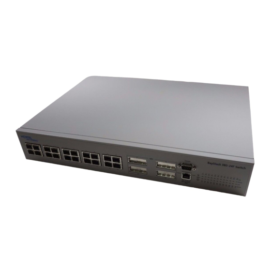
Summary of Contents for Nortel BayStack 380-24F 1000
- Page 1 Part No. 214390-A December 2002 4655 Great America Parkway Santa Clara, CA 95054 Installing the BayStack 380-24F 1000 Switch...
-
Page 2: Statement Of Conditions
Nortel Networks NA Inc. does not assume any liability that may occur due to the use or application of the product(s) or circuit layout(s) described herein. -
Page 3: About This Guide
Adequate space at the front and rear of the switch for access to cables. If you are installing a single BayStack 380-24F 1000 Switch on a table or shelf, make sure the surface will support at least 5 to 10 pounds. -
Page 4: Package Contents
[Draft Level—Nortel Confidential] Package contents Ba yS ta ck 38 0- 24 F Sw itc h 10524FC 1 = BayStack 380-24F 1000 Switch 2 = Rack-mounting hardware: • Rack-mount brackets • Screws for attaching brackets to the switch • Screws for attaching the switch to the equipment rack... -
Page 5: Installing The Switch On A Table Or Shelf
Installing the switch on a table or shelf You can install a single BayStack 380-24F 1000 Switch on any flat surface that can safely support the weight of the switch (5 to 10 pounds). Attach the rubber feet at the marked locations. -
Page 6: Installing The Switch In An Equipment Rack
[Draft Level—Nortel Confidential] Installing the switch in an equipment rack Required tool: Phillips screwdriver for attaching brackets to the switch Rack requirements: • A space of 2.8 inches is provided for each switch in an EIA or IEC standard 19-inch (48.2-centimeter) equipment rack. -
Page 7: Connection Requirements
Pin number Signal Carrier detect (not used) Transmit data (TXD) Receive data (RXD) Data terminal ready (not used) Signal ground (GND) 9473EA Not used Request to send (not used) Not used Ring indicator (not used) Installing the BayStack 380-24F 1000 Switch... -
Page 8: Ac Power Specifications
Refer to the illustration and tables that follow for descriptions of the LEDs on the BayStack 380-24F 1000 Switch. The tables describe LED operation for a switch that has completed its power-on self-tests. Figure 1 BayStack 380-24F 1000 Switch LED display panel BayStack 380-24F Switch Console... -
Page 9: Initial Switch Setup
Initial switch setup The BayStack 380-24F 1000 Switch begins switching as soon as you attach network devices and connect the switch to power. To manage the switch over the network or to perform TFTP operations, you must set certain IP parameters. Refer to Using the BayStack 380-24F 1000 Switch for more information about the console menus and configuring your switch. -
Page 10: Setting Ip Parameters
To set the IP parameters: Connect a terminal to the Console port on a standalone switch. Set the terminal protocol as described in Using the BayStack 380-24F 1000 Switch. Connect the switch to power. After the Nortel Networks logo is displayed, press [Ctrl]-Y to display the Main Menu. - Page 11 [Draft Level—Nortel Confidential] Select IP Configuration/Setup (or press i) to display the IP Configuration/Setup menu. Note: The default management VLAN in the BayStack 380-24F 1000 Switch is VLAN 1. To manage the switch, make sure the network management station is on the management VLAN or is connected to the management VLAN through routers.
- Page 12 [Draft Level—Nortel Confidential] 214390-A...


