Table of Contents
Advertisement
Quick Links
Advertisement
Table of Contents

Related Manuals for Shindaiwa DGK70F


Summary of Contents for Shindaiwa DGK70F
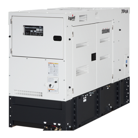
- Page 1 SERVICE MANUAL Disassembly & Assembly DGK70F File № DGO-530_DGK70F...
-
Page 2: Table Of Contents
Table of Contents Attention Statement ········································································ 1 General Safety Instructions ····························································· 2 Disassembly & Assembly ································································· 4 Disassembly ···················································································· 4 1. Remove the battery ········································································ 4 2. Remove the bonnet ········································································ 5 3. Remove the door ··········································································· 8 4. Remove the side door ····································································· 9 5. -
Page 3: Attention Statement
Attention Statement ・Only technicians with enough knowledge and experience should perform maintenance and operational checks after maintenance. ・Before maintenance, always read this service manual as well as the owner’s manual and be familiar with the contents thoroughly before starting the service and maintenance of the equipment. -
Page 4: General Safety Instructions
General Safety Instructions WARNING! ELECTRIC SHOCK Entangled Injuries under By Moving Componen NEVER touch the output terminals during operation NEVER touch the output terminal during NEVER reach or touch moving operation even though the breaker on the components during operation! load is being set at “OFF”... - Page 5 CAUTION! Work Safely! STOP the equipment immediately when Generators and welders operate at very high abnormal circumstances are noticed! STSTOP the equipment immediately whenever speeds and can do serious damage or injury if they are misused or abused. Never abnormal circumstances are noticed such as unusual noise, smell vibration and etc.
-
Page 6: Disassembly & Assembly
DGK70F Disassembly & Assembly WARNING! Before start servicing, prepare; 1. Stop engine and make sure it stopped. 2. Allow the engine and other moving component to cool before servicing. 3. Work on a flat open area. Do not serve the equipment on the tilted ground. -
Page 7: Remove The Bonnet
2. Remove the bonnet (1) Unfasten the 18 bolts (M8 x 20) and 4 bolts (M16 x 30) and remove the bonnet. Right Side :M8 × 20 :M16 × 30 Bonnet:2 bolts (M16×30) Left Side :M8 × 20 :M16 × 30 Bonnet:2 bolts (M16×30) WARNING! Always wear safety shoes, gloves and eye protection for your safety! - Page 8 (M8 x 20) Bonnet:12 bolts...
- Page 9 (2) Loosen the screw that adjusts the metal band and remove the intake hose. Left Side 1. Loosen the screw in the metal band. 2. Remove the intake hose. Intake Hose Screw (3) Remove the negative pressure sensor and mass air flow sensor that locate in the air cleaner.
-
Page 10: Remove The Door
3. Remove the door WARNING! 1. Always wear safety shoes, gloves and eye protection for your safety. Hold the upper door to prevent a fall when removed the hinge pin. (1) Unlock and open the door. (2) Lift the door up slightly until the two hinges separate. Left Side Right Side... -
Page 11: Remove The Side Door
4. Remove the side door WARNING! Remove the bolts in order as per the numbers that are described in 4-(2) for your safety. Incorrect removal may cause for a door fall and serious injury. (1) Remove the 2 bolts (M6 x 16) and open the side door. Left Side Bolt Side Door... - Page 12 (3) Remove the 6 pcs. M12 nuts and 1 pc. of the M8 nut. Unfasten the nut with the wrench and remove the terminal. (M8) 1 location (M12) 6 locations (4) Turn the 2 knobs to counter-clockwise and open the operation panel. Operational Panel Knob (5) Disconnect the connector in the control box.
- Page 13 (6) Remove the bolt (M8 x 35) that tighten the stopper cable. Left Side Bolt Stopper Cable (7) Slightly lift the side door up until the two hinges separate. Left Side Inside view after the panel cover removed.
-
Page 14: Remove The
5. Remove the front cover Disconnect the connector. (1) Disconnect the cable. Loosen the screw (M5 x 10) and unfasten the cable. Loosen the nut (M10) and remove the cable. Left View Disconnect the connector. Loosen the bolt (M10 x 25) and remove the cable. - Page 15 Loosen the bolt (M12 x 25) and remove the cable. Loosen the nut (M8) and remove the cable. Right Side Oil Filter Dynamo Disconnect the connector. Disconnect the connector. Fuel Pump Disconnect the connector.
- Page 16 (2) Removal of the cables between the alternator and front cover. 1. Unlock and open the front door. 2. Slightly lift the front door until the two hinges separate. Front Door Loosen the 5 bolts at the upper of the breaker with a hex.
- Page 17 Loosen the 2 bolts. (M6 x 16) Switch Case Left Side Loosen the 2 bolts (M6 x 16) while holding the switch case. Switch Case Loosen the 3 bolts. (M6 x 16)
- Page 18 Voltage Selector Switch (Top View) (1) Loosen the 8 bolts. (M6 x 12) Left View Right View U1 11 20 30...
- Page 19 (3) Unfasten the 4 bolts (M10 x 25) and separate the front cover and base frame. NOTE: The below photos show the top cover mounted but the cover should already be removed per “2. Remove the bonnet” on page 5. Top Cover Front Cover Left Side...
-
Page 20: Remove The Flexible Tube
6. Remove the flexible tube (1) Remove the 7 nuts (M8) that tighten the flexible tube. Flexible Tube Gasket Right Side 1. Unfasten the 7 nuts (M8). 2. Remove the flexible tube and gasket. NOTE: Carefully remove the flexible tube to prevent a damage of the gasket. Gasket may reuse if it was not visuall damaged. -
Page 21: Remove The Alternator
7. Remove the alternator (1) Unfasten the bolt (M4 x 30) that fit the fan cover. Fan Cover Bolt (M4 x 30) (2) Separate the stator and AV rubber. 1) Remove the 2 nuts (M12) and separate the stator from the AV rubber. - Page 22 4) Slowly pull the nylon slings up and lift the stator. 5) Insert the wooden support between the engine cover and bed until the edge of wood contacts the housing. (3) Remove the 10 bolts and 2 nuts. Separate the stator from the fly wheel housing. 6) Unfasten the 10 bolts (M10 x 55) and 2 nuts (M10) that are directly Bolt...
-
Page 23: Remove The Rotor
(5) Remove the Cover. 9) Unfasten the 3 bolts (M5 x 12) and remove the cover. Bolt 8. Remove the rotor (1) Lift the alternator. 1) Lace the nylon slings through the cooling grid as arrow indicates in the photo. 2) Slowly lift the alternator up with the nylon slings so the fan mounted in the alternator should face up. - Page 24 (2) Separate the rotor. 4) Put the 2 bolts (M10 x 60) through the hole mounted in the rotor on a diagonal line. 5) Fasten the bolt with the eye nut. (M10) Eye Nut (M10) Bolt (M10 x 60) 6) Lace the shackle through the eye nut.
- Page 25 10) Slowly pull the nylon slings up until the rotor separates from the stator. Rotor Stator (3) Lay the alternator on the side to the “flat” floor. 11) Slowly lay the alternator on its side down to the “flat” floor. (4) Remove the housing.
- Page 26 Guide Bolt Housing 15) Slide the housing in front. 16) Unfasten the guide bolt. (M10 x 100) Housing (5) Remove the exciter stator. 17) Unfasten the 4 bolts. (M8 x 40) 18) Remove the exciter stator. Bolt...
-
Page 27: Assembly
Exciter Stator The excitor stator after remved. Assembly 1. Mount the stator and rotor (1) Assemble the rotor. 1) Insert the guide bolt (M10 x 100 and Fly Wheel M10 x 120) to the fly wheel on a diagonal line. NOTE: Use a different length of the bolts to ease installation and alignment of the rotor and stator. - Page 28 4) Temporarily put the 6 bolts (M10 x 60) on a diagonal line. 5) Unfasten the 2 guide bolts. (M10 x 100 and M10 x 120) 6) Torque the 2 bolts (M10 x 60) with a torque wrench. Torque required value described below. 7) Torque the other 6 bolts (M10 x 60) with a torque wrench.
- Page 29 ② Mount the housing. 2) Install the guide bolt (M10 x 100) to the upper of the alternator. 3) Align the guide bolt with the hole in the housing. 4) Torque the bolt #2 and #3 (M10 x 35) with a torque wrench. Torque to the required value.
- Page 30 ④ Assemble the stator. 8) Put the stator housing over the Engine Housing 2 bolts that are mounted to the engine housing. Stator Housing Bolt 9) Put the eye bolt (M16) to the stator Nylon Slings as picture shows. 10) Lace the nylon slings through the eyelet of the eye bolt and pull the rope tight to hold the stator.
- Page 31 11) Fit the stator and the engine housing. 12) Temporarily fasten the 2 bolts (M10 x 55) on a diagonal line until the bearing come toward the engine cover. 13) Fasten the 2 bolts (M10 x 55) until the gap between the stator and engine cover would be approx.
- Page 32 ⑤ Mount the AV Rubber. 20) Slowly lift the stator up and pull the wooden support out. Nylon Slings Eye Bolt 21) Slowly lift the stator down and align the hole mounted on the stay in the stator with the bolt in the AV rubber. 22) Remove the nylon slings and the eye bolt from the stator in order.
-
Page 33: Mount The Flexible Tube
⑥ Assemble the fan cover. 24) Mount the fan cover over the stator housing. Torque the bolt (M4 x 30) with a torque wrench. Torque to the required value. [Fastening Torque] 1.3~1.9 N・m (13~19 kgf・cm) Fan Cover Bolt 2. Mount the flexible tube (1) Mount the Flexible Tube. -
Page 34: Reinstall The Cover And Rewire
3. Reinstall the cover and rewire (1) Reinstall the front cover to the base frame. Nylon Slings WARNING! 1. Hold the front cover with the nylon sling before removing the cover to prevent a fall. 2. Always tightly retain the nylon slings for your safety! Front Cover (2) Retighten the 4 bolts. - Page 35 (3) Wire the engine . (Left Side) NOTE: Torque to the required value with a torque wrench. Torque the screw (M5 x 10) Torque to the nut (M10) to the wire with the cable by a torque harness with a torque wrench. wrench.
- Page 36 (4) Wire the the engine. (Right Side) Retighten the 3 [Fastening Torque] terminals with the 37.0~54.0 N・m (377~551 kgf・cm) bolt (M12 x 25). Retighten the terminal with the nut (M8) [Fastening Torque] 11.0~16.0 N・m (112~163 kgf・cm) Right Side Oil Filter Dynamo Fuel Strainer Connect the connector.
- Page 37 (5) Wire the stator to the terminal bed. Breaker White Blue Blue Control Unit Torque the terminals for #L1 (red), #L2 (white), #L3 (blue), #U (red) and #W (blue) with the 5 hex. bolts. [Fastening Torque] 11.0~16.0 N・m (112~163 kgf・cm) Torque the cable with the screw (M4 x 10).
- Page 38 Torque the 3 bolts (M6 x 16) with a torque wrench. Torque to the required value. [Fastening Torque] 4.3~6.4 N・m (44~65 kgf・cm) Switch Case [Fastening Torque] Torque the 2 bolts (M6 x 16) with a 4.3~6.4 N・m (44~65kgf・cm) torque wrench. Torque to the required value.
-
Page 39: Rewire The Side Door
4. Rewire the side door (1) Lift the side door up and engage the two hinges. Left Side (2) Tighten the stopper with the bolt. (M8 x 35) Left Side [Fastening Torque] 11~16 N・m (112~163 kgf・cm) Bolt Stopper (3) Torque the 6 terminals and 1 terminal with the nuts. (M12 & M8). Blue Black Blue... - Page 40 [Fastening Torque] (4) Fasten the black cover with the 8 bolts. (M6 x 16). 4.3~6.4 N・m (44~65 kgf・cm) Left Side Cover (back) Side Door Bolt (M6 x 16) WARNING! Hold the cover with your hand and keep your safety during retightening. (5) Connect the connectors.
-
Page 41: Reinstall The Bonnet
(7) Refasten the side door with the 2 bolts. (M6 x 16) Left Side [Fastening Torque] 4.3~6.4 N・m (44~65kgf・cm) Side Door 5. Reinstall the bonnet (1) Mount the intake hose. Left Side 1) Reinstall the intake hose to the air cleaner intake. - Page 42 Mass air flow sensor Negative pressure sensor (3) Torque the 18 bolts (M8 x 20) and 4 bolts (M16 x 30) and retorque the bonnet with a torque wrench. Torque to the required value. [Fastening Torque] :M 8×20 :11~16 N・m (112~163 kgf・cm) :M16×30:90~130 N・m (918~1326 kgf・cm)...
- Page 43 (M8 x 20) Bonnet:12 pcs. [Fastening Torque] 11~16 N・m(112~163 kgf・cm) ひ ひ...
-
Page 44: Mount The Door
6. Mount the door 1) Engage the hinges and mount the door. Left Side Right Side... -
Page 45: Mount The Battery
7. Mount the battery 1. Return the battery to the original position in the bed. Connect the clamp and terminal to positive (+) post to the battery first. 3. Connect the clamp and terminal to negative (-) post to the battery. 4. -
Page 46: Tightening Torque
Tightening Torque 1. Specific Tightening Torque Part to be Nomenclature Size Allowance Reference tighten Nm(kgf/cm) Stator, 49.0-56.0 Insert with spring washer. (p/n Bolt M10x55 ASM~Engine (500-571) 90060500010) Stator, 44.2-53.9 Nut, 10 ASM~Engine (451-549) 49.0-56.0 Insert with spring washer. (p/n Rotor~Engine Bolt M10x60 (500-571) - Page 47 Torque Part to be Nomenclature Size Allowance Reference tighten Nm(kgf/cm) Drain Plug~ 68.7-88.2 Install o-ring in the groove with Drain Plug Socket (701-899) lubricant oil. Apply Loctite #638. Fasten as Valve~Socket Valve handle positions upright. Nipple~Valve Nipple Apply Loctite #638. Install O-ring in the groove with Hose Joint~ 49.1-58.8...
- Page 48 Torque Part to be Nomenclature Size Allowance Reference tighten Nm(kgf/cm) Attention direction of the installation on elbow. -Mount the valve among the Exhaust Pipe~ 14.8-21.5 Bolt、Nut 8 M8x70 two pipes. Exhaust Pipe (151-219) -Use the exhaust gasket. -Mount the washer and spring washer with the bolt.
-
Page 49: General Tightening
2. General Tightening Unit: N・m {kgf・cm} Intensity 4.6, 4.8, 5.6, 5.8, 6.3 (4T, 5T, 6T) 8.8, 9.8, 10.9, 12.9 (7T) Tightening Tightening Nominal Tightening Torque Tightening Torque Nominal Strength Nominal Strength Designation Allowance Limit Allowance Limit N{kgf} N{kgf} 0.5 ~ 0.8 1.0 ~... - Page 50 YAMABIKO CORPORATION 35 SHIN-UJIGAMI, KITA-HIROSHIMA-CHO, YAMAGATA-GUN, HIROSHIMA 731-1597 JAPAN Telephone: (81)826-72-5140 Fax: (81) 82-826-72-7004 www.yamabiko-corp.co.jp...