Table of Contents
Advertisement
Quick Links
Advertisement
Table of Contents

Related Manuals for Shindaiwa DGK25F


Summary of Contents for Shindaiwa DGK25F
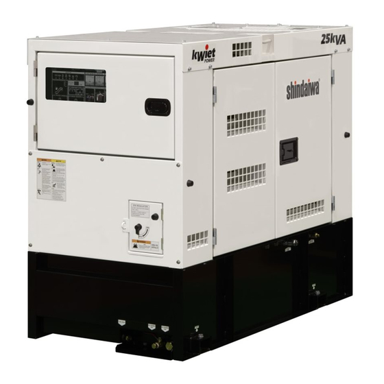
- Page 1 SERVICE MANUAL DGK25F File №DGO-391_DGK25F...
- Page 2 Shindaiwa diesel engine generators, designated as DGK25F It is inevitably necessary to maintain and adjust shindaiwa products periodically in order to use fully and safely for long time. Therefore, understand this service manual fully enough before use and proper maintenance.
-
Page 3: Table Of Contents
Table of Contents 1. Attention Statements ················································································ 2. General Safety Instructions ····································································· 3. Specifications ······························································································ 4. General ········································································································· 4-1 Dimension ·························································································· 5 5. General Par ts Description ································································ 7 5-1 Main Parts and Feature ········································································· 7 5-2 Main Components ················································································ 8 6. -
Page 4: Attention Statements
1. Attention Statements ・Technicians only who own enough knowledge and experience should work for maintenance and operational check after maintenance. ・Before maintenance, always read this service manual as well as owner’s manual and familiarize contents thoroughly before starting the service and maintenance of the equipment for understanding of the equipment, safety instructions and cautions. -
Page 5: General Safety Instructions
2. General Safety Instructions WARNING ELECTRIC SHOCK Entangled Injuries under NEVER touch the output terminals Moving Componen during operation NEVER touch the output terminal during NEVER reach and touch the moving operation even though the breaker on the component during operation! load is being set at “OFF”... - Page 6 CAUTION STOP the equipment immediately when Work Safely abnormal circumstances are noticed! Generators and welders operate at very high STSTOP the equipment immediately whenever speeds and can do serious damage or injury abnormal circumstances are noticed such if they are misused or abused. Never allow a as unusual noise, smell, vibration and etc.
-
Page 7: Specifications
3. Specifications Model Unit DGK25F Revolving Field Brushless Generator Type Rated Frequency Three phase Rated Output(Prime) 15 [7.5] *1 Single phase 15 [7.5] *1 27.5 Three phase Standby Output 16.5 [8.3] *1 Single phase 16.5 [8.3] *1 Three phase 208/240/ [480] *1... -
Page 8: General
4. General 4-1 Dimension Unit in the drawings below is shown by mm. -
Page 10: General Parts Description
5. General Parts Description 5-1 Main Parts and Feature (1) Serial Number Engine Serial Number Unit Serial Number... -
Page 11: Main Components
5-2 Main Component ⑳ Voltage Selector Switch Feature: Switch to change the voltage. Caution This switch should never be changed while the generator is running or serious damage may occur. - Page 12 Panel Inside ECM (Engine Control Module) Engine Operation Switch Feature: Control engine in accordance to emission standard. Engine Operation Switch Table Nomenclature Function Remarks Maintain rated speed (1800 rpm) ISOCHLONOUS automatically at any load factor. Increase up to 110% of rated rpm. SPEED INC.
- Page 13 Output Terminal Cover Inside Terminal Rest Feature: Relay terminal block of the power output from the alternator. Circuit Breaker (1-Phase 240/120) Circuit Breaker (1-Phase) Feature: Protect electrical circuit Feature: Protect electrical circuit from damage caused by from damage caused by overload or short-circuit.
- Page 14 Air Cleaner Feature: Clean intake air. Pre Fuel Filter Feature: Filter water or dust in the fuel. Main Fuel Filter Feature: Filter water or dust in the fuel. Accessory Standard Accessory ① Owners Manual ② Starter Key – 2 sets ③...
-
Page 15: Service Data
6. Service Data ELECTRIC SHOCK WARNING Never touch the output terminals during operation. Never touch the output terminal during operation even though the breaker on the load being set at OFF. Be sure to check and confirm the engine stop whenever touching terminals to connect loads. 6-1 Technical Specification Items Reference Value... -
Page 16: Generator
6-2 Generator Thermo label Rear bracket Main stator Exciter armature Bolt Thermo label Main bearing Exciter stator Rotor Exciter field Armature Fan cover Stator Rotor... -
Page 17: Exciting Amperage
(1) Exciting Amperage Amperage fluctuates based upon the winding temperature. Following is for reference only. Frequency/Rated Output Load Exciting Amperage (Measured) No load 0.34A 3-Phase 60Hz: 20 kW Full load( power factor=1.0) 0.60A (2) Resistance Value Nominal resistance of the winding is tolerated within ±... - Page 18 2. Armature (Main Stator ) #2 when the voltage selector switch is set at 240V: Measure the resistance among the U-W by the low ohm tester. Each shall be 0.16Ω. 3. Excitation Winding (Main Stator) Remove the wire harness from the AVR and measure; The resistance among A~B, B~C and C~A by the low ohm tester.
- Page 19 4. Stator J (Gray)-K(Violet) K (Vi) J (Gr) 23.2Ω. Measure resistance among the J~K by the low ohm tester. It shall be 5. Rotor There are two windings in the rotor and measure the resistance between #1~#4 and #2~#3. Rotor Rectifier Remove the varnish by a sand paper and measure;...
-
Page 20: Tightening Torque
7. Tightening Torque 7-1 Specific Tightening Torque Torque Part to Allowance Nomenclature Size Reference tighten Nm(kgf/cm) 3.0-4.9 Exciter Stator Bolt M5x45 (30-50) Rear Bracket 29.5-32.3 Bolt M12x160 (Main Stator) (300-330) Bolt, 19.7-24.5 Generator Stator M10x30 Shim (200-250) 40.7-49.5 Rotor Bolt M10x1.25x30 (415-505) Bolt,... -
Page 21: General Tightening Torque
7-2 General Tightening Torque Unit: N・m {kgf・cm} Intensity 4.6, 4.8, 5.6, 5.8, 6.3 (4T, 5T, 6T) 8.8, 9.8, 10.9, 12.9 (7T) Tightening Tightening Nominal Tightening Torque Tightening Torque Nominal Strength Nominal Strength Designation Allowance Limit Allowance Limit N{kgf} N{kgf} 0.5 ~ 0.8 1.0 ~... -
Page 22: Periodical Check For Engine
8. Periodical Check for Engine ●Consult Kubota Service Dealer ○User Check ◎Replace Parts Checking interval Start up Items Check Every Every Every Every Every 50hrs 100hrs 200hrs 400hrs 1000hrs 2000hrs ○ Check and Supply Fuel Check and Supply Engine ○ ◎... -
Page 23: Trouble Shooting
9. Trouble Shooting 9-1 Engine Note: As this unit is equipped with a Tier 4 engine, use “E-IDSS” for is a diagnosis. Note: Refer to “ISUZU NONROAD DIESEL ENGINES MEETING INTERIM TIER 4 EMISSIONS REGULATIONS E-IDSS introduction” for the details of the error code. 9-2 Generator <... - Page 24 Problem Possible Cause Inspection Remedy High output voltage. 1. Faulty volt meter. 1. Check the voltage of the volt meter 1. Replace the volt meter. 2. Faulty adjusting AVR. 2. Check the dial gauge [VR1] on the 2. Adjust the voltage properly. AVR.
-
Page 25: Engine Error Code
10. Engine Error Code 10-1 Error Code (Digital Display) This unit is equipped with monitoring function. When it detects the engine error, the monitor lamp would illuminate. Refer to the “12. Engine Error Code Chart” for the details in this manual on pages 49-52. Error Code Display Engine Monitor Lamp... - Page 26 Note a) Past record of malfunction is stored in the ECM (Engine Control Module) even after the past malfunction had cured. b) Each engine code displayed in the “engine output monitor” and “engine monitor panel” is not identical. c) Monitor lamp does not function when engine is running. The monitor lamp will blink when there was no malfunction today and in the past.
-
Page 27: After Repair
“Monitor Lamp” Flashing – when the monitor lamp will blink 3 times and twice shorter, it shows the engine code “32”, for example. Monitor Lamp: ON Monitor Lamp: OFF t1= approx.0.3 sec. t2= approx. sec. 1 digit 10th digit t3= approx.1.2 sec. t4= approx.2.4 sec. - Page 28 4) Disconnect the 1-pin connector from a battery and release the “engine operation button”. 5) Turn and remain the starter switch to “STOP” for more than 10 sec. 6) Turn the starter switch to “RUN”. 7) When there is no past record displayed when the “memory clear button” is pressed, it completed the elimination work.
-
Page 29: Wiring Diagram
11. Wiring Diagram... - Page 31 YAMABIKO CORPORATION 35 SHIN-UJIGAMI, KITA-HIROSHIMA-CHO, YAMAGATA-GUN, HIROSHIMA 731-1597 JAPAN Telephone: (81)826-72-5140 Fax: (81) 826-72-7004 www.yamabiko-corp.co.jp...