Table of Contents
Advertisement
Quick Links
Advertisement
Table of Contents

Related Manuals for Shindaiwa DGK150DU


Summary of Contents for Shindaiwa DGK150DU
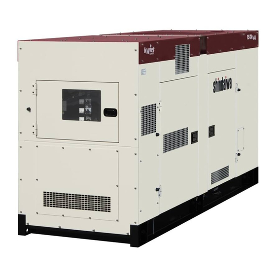
- Page 1 S AND OPERATOR S MANUAL Vertical, Water-Cooled 4-Cycle Diesel Engine CAUTION Do not operate the Generator, or any other appliance, before you have read and understood the instructions for use and keep near for ready use. DGK150DU/01 X750-022 32 5 X750801-400 5...
- Page 3 Introduction Thank you for purchasing this Shindaiwa soundproof diesel engine generator. This manual has been created to ensure safe usage of this generator. Be sure to read this manual before operation. Improper operation/handling of this generator will result in an accident or malfunction.
-
Page 4: Table Of Contents
Table of Contents Safety Instructions ................2 2. Specifications ................... 5 2-1. Specifications ................5 2-2. Ambient Conditions ..............6 Applications ..................6 Part Names ..................6 4-1. External View/Part Names ............6 4-2. Operation Panel Part Names ............ 8 4-3. -
Page 5: Safety Instructions
Safety Instructions WARNING : SUFFOCATION FROM EXHAUST FUME Do not operate the generator in poorly ventilated areas such as indoors or tunnels, as the exhaust gas of the engine contains substances that are harmful to human health. Do not direct exhaust fumes at pedestrians or buildings. WARNING : ELECTRIC SHOCK Before connecting or disconnecting the load cables to/from the output terminal, always turn the output circuit breakers to the OFF position, stop the engine, and remove the engine key. - Page 6 CAUTION : EYE/SKIN INJURY Wear rubber gloves and other protective wear to protect eyes, skin and clothing from the battery fluid which contains diluted sulfuric acid. If the battery fluid contacts eyes or skin, wash out immediately with a sufficient amount of clean water. Be sure to receive medical treatment, especially if the fluid contacts the eyes.
- Page 7 Before starting operation, always be sure to turn off all switches of equipment using the generator and all breakers to OFF. Do not move the generator during operation. Do not operate the generator if it has been modified or any parts have been removed. CAUTION : PROPERTY DAMAGE If using this generator for medical equipment, check before use with the medical equipment manufacturer, doctor, hospital or similar entity.
-
Page 8: Specifications
2. Specifications 2-1. Specifications Model Unit DGK150DU/01 Rotating Filed, Brushless 3-Phase Generating Type Synchronous Alternator Rated Output Voltage – Three phase 208 / 480 Voltage – Single phase 120 / 240 / 277 Three phase – 480V Three phase – 208V Amps Single phase –... -
Page 9: Ambient Conditions
2-2. Ambient Conditions Use this generator in ambient conditions as described below. Failure to provide these conditions can result in problems such as malfunction, insufficient output and reduced durability. ■ Ambient temperature: 5 to 104 ° F ( -15 to 40 ° C ) ■... - Page 10 LEFT SIDE Engine Check Door Coolant Sub-Tank Air Cleaner PCV Filter Voltage Selector Switch Terminal Cover Alternator Check Door Fuel Inlet Fuel Tank Receptacle Panel Cover Receptacle Panel Fuel Filter Electromagnetic Pump Oil Filler Cap & Oil Level Indicator Oil Filter Fuel Drain Water Sedimenter Oil Drain...
-
Page 11: Operation Panel Part Names
4-2. Operation Panel Part Names Circuit Breaker Voltage Adjust Regulator Pilot Lamp Monitor Lights Panel Light Hour Meter Voltmeter Water Temperature Gauge Ammeter Oil Pressure Gauge Frequency Meter Fuel Gauge Auto start Panel (Optional) Glow Lamp Auto start Switch (Optional) Emergency Stop Button Panel Light Switch Starter Switch... -
Page 12: Main Terminal Board
4-3. Main Terminal Board Main Terminals Plexiglass Cover 4-4. Receptacle Panel < NOTE > All duplex receptacles are GFCI protected and are rated at 20 amps. All twist loc receptacles are rated at 30 amps. -
Page 13: Equipment
Equipment 5-1. Warning Indicators WARNING : INJURY Close all doors and place locks during operation, to avoid injuries by unintentionally contact with moving parts such as the cooling fan and fan belt. Before performing any equipment check or maintenance, stop the engine, and remove the engine key. - Page 14 (1) WATER TEMP (Coolant Temperature) Warning Indicator (High Water Temp) CAUTION: BURNS Do not open the radiator cap immediately after stopping the engine, to avoid sustaining burns from hot vapor. Hot steam gushes out from the coolant sub-tank if the generator overheats. Do not touch the coolant sub-tank.
- Page 15 (4) Diagnosis Indicator CAUTION: BURNS Always be sure to stop the engine and allow the engine to cool when performing inspection or maintenance of engine oil. Opening the oil gauge or oil filler cap during operation will result in hot oil cause personal injury. If the electronic control module detects a fault that could affect engine operation it will flash the diagnosis lamp to indicate that further diagnosis as to the source of fault is necessary.
-
Page 16: Meters And Gauges
5-2. Meters and Gauges Engine Meters and Gauges (1) Hour Meter Displays the operating time. Use this to schedule periodic inspection. Be careful as the hour meter operates when the starter switch is at RUN regardless of whether the engine is running or stopped. - Page 17 Generator Meters and Gauges (1) Voltmeter The volt meter displays the voltage output from the generator. The voltage will be displayed depend on the position of the voltage selector switch. Only L1 or L3 voltage will be displayed for single-phase operation. (2) Ammeter The amp meter displays the electrical current output from the generator.
- Page 18 (2) Pilot Lamp The pilot lamp is located on the generator control panel and indicates whether or not the engine is running. When the lamp is lit the engine is running. When the lamp is not lit the engine is not running. (3) Panel Light The panel light is located on the generator control panel and is used to illuminate the generator and engine control panels.
- Page 19 (2) Emergency Stop Button This button is used to stop the engine in emergency. Keep pressing the button until the engine comes to complete stop. < NOTE > Keep pressing the button until the engine stops in several seconds. After the engine stops, be sure to return the starter switch to the <STOP>...
- Page 20 (5) Voltmeter Selector Switch The voltmeter selector switch is a 5 position switch located on the control panel to the left of the voltmeter. The voltmeter selector switch selects which phase voltage is displayed on the voltmeter. Positions: Off: There are two off positions on the voltmeter selector switch. One at the full clockwise position and one at the full counter-clockwise position of the switch.
- Page 21 Voltage Regulator / Engine Speed Switch (1) Voltage Regulator The dial adjusts generator output voltage. Turn the dial clockwise to increase, or counter-clockwise to decrease the voltage. (2) Engine Speed Switch Throttle Switch Set the toggle switch to “START” position for warm-up or cool-down the engine, and set to “RUN”...
-
Page 22: Voltage Selector Switch
5-3. Voltage Selector Switch The voltage selector switch is located above the terminal panel. The lockable voltage selector switch makes a quick and convenient method of changing the generator output voltage. < NOTE > Serious damage may occur when the selector switch is changed while generator is running. -
Page 23: Fuel Piping Switch (3Way Fuel Valve)
5-4. Fuel Piping Switch (3Way Fuel Valve) CAUTION: Always make sure that the engine is stopped when working on fuel line. Always be sure to wipe up any spilled fuel. After working on the piping, check that there is no Diesel fuel leakage. By switching three-way valve, fuel will be supplied from the external tank. -
Page 24: Transporting/Installing
Transporting/Installing 6-1. Transport Procedures WARNING : INJURY Always be sure to use lifting hooks when lifting up the generator. The other thing could result in the generator falling. This lifting hook is designed to lift the generator only. Do not lift any additional added weight such as fuel tanks and/or trailers with this lifting hook. -
Page 25: Installation Procedures
6-2. Installation Procedures WARNING : SUFFOCATION FROM EXHAUST FUME Do not operate the generator in poorly ventilated areas such as indoors or tunnels, as the exhaust gas of the engine contains substances that are harmful to human health. Do not direct exhaust fumes at pedestrians or buildings. CAUTION : FIRE Do not bring flammable items (such as fuel, gas and paint) or items that are highly combustible near the generator as the muffler, exhaust gas and other... -
Page 26: Load Connections
Load Connections 7-1. Load Cable Selection CAUTION : PROPERTY DAMAGE Cable burnout can occur due to generated heat if the load current exceeds the allowable current of the cable. The voltage drop between cables is large if the cable is excessively long or thin, resulting in decreased input voltage to equipment using the generator, thereby causing decreased performance, faulty operation and malfunction. -
Page 27: Connecting Load Cables
7-2. Connecting Load Cables WARNING : ELECTRIC SHOCK Before connecting or disconnecting the load cables to/from the output terminal, always turn the output circuit breakers to the OFF position, stop the engine, and remove the engine key. The person performing the maintenance should always keep the key. Close the output terminal cover before operating. - Page 28 ● 208 Volt Three Phase and 120 Volt Single Phase Switch Position ● 240 Volt Single Phase and 120 Volt Single Phase Switch Position < NOTE > Select the voltmeter selector switch for L3-L1 position and the ammeter selector switch for L1 or L3 position when the Voltage Selector Switch is set for 1 Phase 240/120V position.
-
Page 29: Pre-Operation Inspection
Pre-Operation Inspection WARNING : ELECTRIC SHOCK/ / / / INJURY Before performing any equipment check or maintenance, stop the engine, and remove the engine key. A person performing the maintenance should always keep the key. Close all doors and place locks during operating this equipment, to avoid injuries by unintentionally touching cooling fan and fan belt. -
Page 30: Checking Coolant
(1) Types of Engine Oil Use the API class CD grade or higher. (2) Engine Oil Viscosity Use a diesel engine oil with an appropriate viscosity corresponding to the ambient temperature (refer to the table). Relation of Viscosity/Temperature SAE40 SAE20/20W SAE10W SAE30... -
Page 31: Checking The Fan Belt
(2) Filling the Radiator Radiator Cap Remove the radiator cap. Fill with coolant through the filler neck until the radiator is full. Re-attach and tighten the radiator cap. Sub-tank < NOTE > Use a 50:50 mix of Long Life Coolant (LLC) for engine coolant. Use GM SPEC 6277M or equivalent. -
Page 32: Checking The Fuel
(2) Fan Belt Condition Check the fan belt for damage and replace if any damage or other fault is found. (3) Replacing the Fan Belt Request the authorized distributor where the generator was purchased to replace the fan belt. < NOTE > Use of a loose or damaged fan belt could result in overheating or insufficient charging. -
Page 33: Checking For Fuel, Oil And Coolant Leaks
The engine is designed to use either Number 1-D or No. 2-D diesel fuel. However, for better fuel economy, use No. 2-D diesel fuel whenever possible. At temperatures less than 19.4 ° F ( -7 ° C ), No.2-D fuel may pose operating problems (see “Cold Weather Operation”... - Page 34 TERMINAL TERMINAL ■Replacing the Battery < NOTE > Two batteries are connected in series order. Whenever you replace battery or disconnect cables, always proceed with the following steps, otherwise battery Fixing Rod may short-circuit. BATTERY - A BATTERY - B (1) BATTERY - A Remove the clamp and cable from negative (-) post from the battery on the right side (always remove negative side first).
-
Page 35: Operating Procedures
Operating Procedures 9-1. Initial Startup/Pre-Check WARNING : SUFFOCATION FROM EXHAUST FUME Do not operate the generator in poorly ventilated areas such as an indoors or tunnels, as the exhaust gas of the engine contains substances that are harmful to human health. Do not direct exhaust fumes at pedestrians or buildings. - Page 36 Circuit Breaker Throttle Switch Glow Lamp Starter Switch Voltage Adjust Regulator After starting the engine, remove your hand from the starter switch. Keep the idling rpm for approximately 10 minutes. Turn the throttle switch to RUN. Adjust the voltage regulator dial to the specified voltage. For three-phase load 60Hz 480V / 208V...
-
Page 37: Voltage Switching Function
9-2. Voltage Switching Function WARNING : ELECTRIC SHOCK If performing any electric voltage switching, turn all breakers to OFF position and stop operation. Lock the generator using a padlock to be operated by designated operators only. CAUTION : PROPERTY DAMAGE Check that the voltages of the generator output setting, output terminal connection and load power source are consistent. -
Page 38: Procedures During Operation
9-3. Procedures during Operation (1) Checks after Startup Make sure that all meters and indicators are in normal status. (Refer to section “5. Equipment”) Check that there is no abnormal vibration or noise. Check that the exhaust gas color is normal. When operation is normal, the exhaust gas should be colorless or slightly bluish. -
Page 39: Protective Functions
9-5. Protective Functions WARNING : INJURY Close all doors and place locks during operating this equipment, to avoid injuries by unintentionally touching cooling fan and fan belt. Before performing any equipment check or maintenance, stop the engine, and remove the engine key. A person performing the maintenance should always keep the key. -
Page 40: Connecting With External Fuel Tank
9-6. Connecting with External Fuel Tank CAUTION : FIRE Always make sure that the engine is stopped when working on the fuel line. Always be sure to wipe up any spilled Diesel fuel. After working on the piping, check that there is no Diesel fuel leakage. Turn the 3way fuel valve lever to the “A”... -
Page 41: Inspection/Maintenance
10. Inspection/Maintenance WARNING : ELECTRIC SHOCK/ / / / INJURY Before performing any equipment check or maintenance, stop the engine, and remove the engine key. A person performing the maintenance should always keep the key. Do not touch the generator if the Alternator or casing becomes wet during operation. - Page 42 When check doors are open during maintenance, take measures so that unrelated personnel cannot accidentally come close to the generator. Close all doors and covers if you are going to be away from this generator. In the event you are using Fuel Oil (A) as a fuel, the interval of replacing engine oil, oil filter and fuel filters and the inspection of fuel injection nozzle will be more frequently at every half the hours shown in the matrix.
- Page 43 (1) Engine Oil Replacement First Time 50 hours Oil Filler Cap ( Oil Level Indicator ) Thereafter Every 500 hours Remove the oil filler cap. Remove the oil drain plug, and turn the spigot counterclockwise to open the ball valve and drain the engine oil.
- Page 44 Oil filter tightening torque: 63.7 ± 4.9 Nm ( 6.5 ± 0.5 kgfm / 47.0 ± 3.6 lbf・ft ) < NOTE > Request the authorized distributor where the generator was purchased to perform this procedure if you do not have a filter wrench. Oil filter part no ISUZU Part No.
- Page 45 < NOTE > Always make sure that the arrow mark on the cleaner cap is pointing upward. Clog Indicator Clean more frequently, if used in dusty environment. Outer element : ISUZU Part No. 114215-1880 Inner element : ISUZU Part No. 114215-0340 To clean the air filter element: If the element has dried contaminants, it may be cleaned by blowing compressed air from...
- Page 46 < NOTE > After draining finishes, extract the air in fuel line. (Refer to “9-3. Procedures during Operation”) (6) Cleaning / Changing Fuel Filter and Water Sedimenter Air-Bleeding Plug Clean Every 250 hours Replace Every 500 hours Loosen the air-bleeding plug. Loosen the drain plug on the bottom to drain the fuel.
- Page 47 (7) Fuel System Air Bleeding The entry of air into the fuel system will cause hard engine starting or engine malfunction. When performing maintenance such as emptying the fuel tank, draining for the water sediment, and the fuel filter element is done, be sure to conduct air bleeding procedure. Loosen the air bleeding screw located on top of the main fuel filter housing.
- Page 48 Electromagnetic Pump Filter element : ISUZU Part No. 898071-4010 Electromagnetic Pump Gasket : ISUZU Part No. 898071-4040 (9) Clean Strainer in Engine Feed Pump ( Fuel Suppuly Pump ) Clean Every 500 hours Remove eyebolts. Remove strainer in eyebolts. Clean the strainer with the compressed air and rinse it in the fuel oil and reinstall in the reverse order.
- Page 49 (10) Draining Water from Fuel Tank Drain water Every 250 hours Ball Valve Remove the fuel drain plug, and turn the spigot counterclockwise to open the ball valve and drain the water. After the water has been completely drained, turn the spigot clockwise to close the ball valve, and tighten the fuel drain plug.
- Page 50 (12) Bleeding air from EGR cooler Bleeding air Every after coolant change Loosen the air release plug of the EGR cooler in order to bleed air from within the EGR and improve cooling performance. When coolant flows out from the air release plug, tighten the air release plug. Air bleeder plug tightening torque: 19.0 to 25.0 Nm ( 1.9 to 2.5 kgfm / 14.0 to 18.4 lbf・ft.
-
Page 51: Long-Term Storage
11. Long-Term Storage WARNING : INJURY Before performing any equipment check or maintenance, stop the engine, and remove the engine key. A person performing the maintenance should always keep the key. CAUTION : FIRE Always be sure to wipe up any spilled fuel or oil. Allow the generator to cool before covering with the protective cover. -
Page 52: Troubleshooting
(2) Double-Stacking Procedures WARNING : INJURY Always be sure to observe the following items when double stacking this generator in a warehouse or similar location. Check that the Top cover of this generator is not dented, and that bolts are not loosen or missing. Set in a location with a flat hard floor capable of withstanding the double-stacking weight. - Page 53 Problem Suspected cause Action Starter motor Battery output is weak Check/ battery liquid/ or Charge does not drive Battery is deteriorated Change battery or speed is low. Battery terminal is OFF or loose Fix/Tighten terminal Battery terminal is corroded Clean terminal Starter switch or relay is defective Contact your distributor to repair Starter motor is defective...
- Page 54 1. Air filter element is clogged 1. Check/Change air filter element 2. Fuel injection nozzle is defective 2. Contact your distributor to repair 3. Improper fuel is used 3. Change to clean fuel White smoke comes 1. Too much or too little oil to cylinder 1.
-
Page 55: Generator Circuit Diagram
13. Generator Circuit Diagram... -
Page 56: Engine Electrical Circuit Diagram
14. Engine Electrical Circuit Diagram... - Page 58 ©2016...