Table of Contents
Advertisement
Quick Links
Advertisement
Table of Contents

Related Manuals for Tenda W15E


Summary of Contents for Tenda W15E
- Page 1 AC1200 Wireless Hotspot Router W15E User Guide...
- Page 2 Tenda reserves the right to make changes to the products without obligation to notify any person or organization of such revisions or changes. Tenda does not assume any liability that may occur due to the use or application of the product described herein. Every effort has been made in the preparation of this document to ensure accuracy of the contents, but all statements, information and recommendations in this document do not constitute a warranty of any kind, express or implied.
- Page 3 Preface Thank you for choosing Tenda! Please read this user guide before you start with W15E. Conventions The typographical elements that may be found in this document are defined as follows. Item Presentation Example Cascading menus > System > Live Users...
- Page 4 For more information, search this product model on our website at http://www.tendacn.com. Technical Support If you need more help, contact us by any of the following means. We will be glad to assist you as soon as possible. Canada: 1-888-998-8966 support@tenda.cn Hong Kong: 00852-81931998 Hotline Email http://www.tendacn.com...
-
Page 5: Table Of Contents
Contents Get to Know Your Device ............................. 1 1.1 Overview ................................ 1 1.2 Features ................................. 1 1.3 Appearance ..............................1 1.3.1 Front Panel ............................1 1.3.2 Rear Panel ............................2 1.3.3 Label ..............................2 1.4 Packing List ..............................3 Installing the Router ............................4 2.1 Installation Notes ............................ - Page 6 5.3.2 Modifying the LAN IP ........................23 5.3.3 Configuring the DHCP Server Parameters ..................24 5.3.4 DHCP Reservation ..........................24 5.4 Port Mirroring .............................. 25 5.4.1 Overview ............................25 5.4.2 Example of Port Mirroring ........................ 26 5.5 Static Routing ............................... 28 5.5.1 Overview ............................
- Page 7 Filter Management ............................55 7.1 IP Group & Time Group..........................55 7.1.1 Overview ............................55 7.1.2 Adding a Time Group ........................56 7.1.3 Adding an IP Group ........................... 57 7.2 IP Filter ................................. 57 7.2.1 Overview ............................57 7.2.2 Adding an IP Filter Rule ........................59 7.2.3 Example of IP Filter ...........................
- Page 8 8.4.3 Verification ............................88 VPN Service ................................ 89 9.1 PPTP/L2TP Client ............................89 9.2 PPTP/L2TP Server ............................91 9.3 IPSec ................................93 9.4 Example of PPTP/L2TP Configuration ......................97 9.4.1 Networking requirement ........................97 9.4.2 Solution ............................. 97 9.4.3 Configuration procedure ........................98 9.4.4 Verification ............................
- Page 9 11.3.4 Verification ............................ 122 PPPoE Authentication ..........................124 12.1 Basic Settings ............................124 12.1.1 Overview ............................124 12.1.2 Enabling PPPoE Authentication ....................126 12.2 User Management ........................... 127 12.2.1 Overview ............................127 12.2.2 Adding a PPPoE Account ....................... 128 12.3 Example of PPPoE Authentication ......................129 12.3.1 Networking requirement ......................
- Page 10 14.4.2 Adding a DDNS rule........................150 14.4.3 Example of DDNS .......................... 151 Maintenance ............................155 15.1 Login Password ............................155 15.1.1 Overview ............................155 15.1.2 Modify the Login Password ......................156 15.2 Reboot ..............................156 15.2.1 Overview ............................156 15.2.2 Manual Reboot ..........................157 15.2.3 Automatic Reboot .........................
- Page 11 System Status ............................168 16.1 System Info .............................. 168 16.2 Live Users ..............................169 16.3 Traffic Statistics ............................171 16.4 Defense Logs ............................172 16.5 System Logs.............................. 173...
-
Page 12: Get To Know Your Device
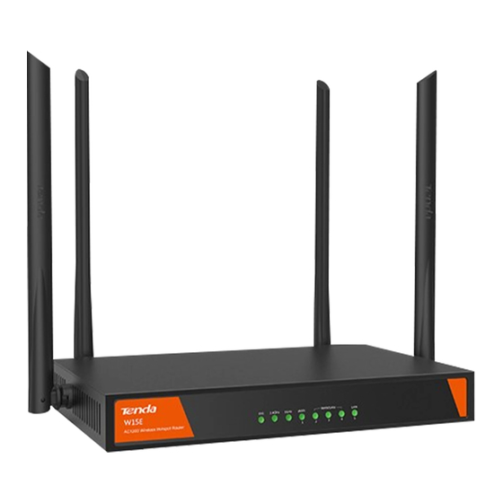
Tenda W15E is a 1200 Mbps 11AC dual-band wireless router dedicated for small and medium enterprises and chain hotels. With high-performance processor operating at a frequency of as high as 900 MHz, W15E supports up to 4 WAN ports, and integrates WeChat authentication, Web authentication, multi-WAN load balancing, and intelligent bandwidth control. -
Page 13: Rear Panel
Description When booting, Solid on indicates that the system is powered on; after the system is started, Solid on indicates that the system is faulty; Blinking indicates that the system works properly, and Off indicates that the system is not powered on. Solid on: The 2.4 GHz wireless function is enabled but no data is transmitted;... -
Page 14: Packing List
(1): IP address of the router. You can use this IP address to log in to the web UI of the router. (2): Serial number of the router. (3): Default wireless network name (WiFi name) of the router. The clients can scan and connect to the wireless network, and log in to the web UI of the router for setting. -
Page 15: Installing The Router
Installing the Router Installation Notes Follow the notes below to avoid device damages or personal injuries caused by misoperation. 2.1.1 Safety Precautions Power on the device using the power adapter included with the package. Make sure that the input voltage matches the value specified on the label of the device. ... -
Page 16: Installing The Router
Installing the Router Step 1 Place the router upside down on the workbench, and paste the four pad stickers into the round recesses in the coroner of the device. Step 2 Place the router right side up on the workbench, and adjust the position of the antennas. See the following figure. - Page 17 adapter included with the package.
-
Page 18: Internet Connection Setup
Internet Connection Setup Step 1 Set the local connection of your computer to Obtain an IP address automatically and Obtain DNS server address automatically. See Configure IP Address of Your Computer in Appendix 1 for detailed instructions. Step 2 Start a browser, enter tendawifi.com or 192.168.0.1, and press Enter. Click Start. - Page 19 Step 3 The system automatically detects your internet connection type. Enter related values according to the on-screen instructions, and click Next. Step 4 Set your SSID and WiFi password, and click Next.
- Page 20 ---End By default, the Set the wireless password as login password is enabled. You can also disable this option and customize your login password.
- Page 21 Wait a second for the completion of settings. For more settings, visit http://www.tendacn.com to download user guide of the router. By default, the wireless network has no password. You need to reconnect to the WiFi signal once the SSID and/or WiFi ...
-
Page 22: Managing Devices
Managing Devices Log in to the Router Web UI Step 1 Set the local connection of your computer to Obtain an IP address automatically and Obtain DNS server address automatically. See Configure IP Address of Your Computer in Appendix 1 for detailed instructions. -
Page 23: Log Out Of The Router Web Ui
---End The router web UI appears. Log out of the Router Web UI If you log in to the web UI of the router and perform no operation within 5 minutes, the router logs you out. Clicking Logout in the upper right corner of the web UI can log you out as well. Click here to logout Web UI Layout The web UI is composed of three parts, including the level-1 and level-2 navigation bars, and configuration area. - Page 24 Name Description The navigation bar displays the level-1 function menu of the router. Choosing the Level-1 function in level-1 navigation bar will expand the corresponding level-2 navigation ❶ navigation bar bars. The navigation bars display the function menu of the router. When you select a Level-2 ❷...
-
Page 25: Network Settings
Network Settings This Chapter includes the following sections: Internet Settings: This module enables to view and modify the internet settings of the router. WAN Parameters: This module enables you to modify the WAN parameters, including WAN speed, MTU, and MAC address. - Page 26 Parameter description Parameter Description It is used to configure the number of WAN ports, and view the status of RJ45 ports (connection status and types of the ports).One WAN port is enabled by default. If you modify the number of WAN ports, the status of RJ45 ports changes as well. See the following figure.
-
Page 27: Pppoe
Parameter Description Primary/Secondary information, ask your ISP. It specifies the connection status of WAN ports. The connection status includes: Connected: The router connects to the internet successfully. Connecting…: The router is connecting to the internet. Connection Status Disconnected: The router is disconnected, or connection fails. In this case, check ... -
Page 28: Static Ip
---End Wait a second. You can access the internet when the connection status is Connected. 5.1.3 Static IP If your ISP provides a fixed IP address, you can choose Static IP as the connection type. The following describes the configuration steps. Step 1 Choose Network >... -
Page 29: Configuring Mac Address Cloning
Parameter description Parameter Description It specifies the WAN speed of the router. Auto-negotiation is selected by default. You are WAN Speed recommended to retain the default value. Maximum transmission unit (MTU). It specifies the size of the largest data packet that can be transmitted by the router. -
Page 30: Lan Settings
Make sure that the MAC address cloned is the MAC address of the computer that can access the internet without the router. LAN Settings 5.3.1 Overview This section enables you to modify the IP address of the LAN port, DHCP server parameters, and to bind/unbind the MAC address and IP address of the clients. - Page 31 LAN IP LAN IP is the management IP address of the router, which can be modified if necessary. Parameter description Parameter Description It specifies the IP address of this router’s LAN port, namely the IP address for logging in to the web UI of the router.
- Page 32 When the lease time expires: If the client is still connected to the router, the client automatically extends the lease time and continues to use this IP address. If the client is disconnected (the client is shutdown, the Ethernet cable is plugged out, ...
- Page 33 Manual DHCP Reservation The client obtains the same IP address assigned by the DHCP server all the time so as to enable the Filter Management, Bandwidth Control, and VPN, and so on. Manual DHCP Reservation module enables you to manually bind the IP address and MAC address of the client. Adding a Rule Step 1 To access the Manual DHCP Reservation module, choose Network >...
-
Page 34: Modifying The Lan Ip
Parameter description Parameter Description This button enables you to manually bind a static IP address for the client. To bind, you need to know the MAC address of the client. It is used to delete the selected bind rule of the IP address and MAC address. IP Address It specifies the IP address corresponding to the MAC address of the client which it assigned to. -
Page 35: Configuring The Dhcp Server Parameters
5.3.3 Configuring the DHCP Server Parameters Step 1 To access the DHCP Server module, choose Network > LAN Settings. Step 2 DHCP Server: Click Enable. Step 3 Start/End IP: Set the start IP and end IP of the IP address pool that the DHCP server can automatically assign to the clients. -
Page 36: Port Mirroring
In the windrow that appears, enter the MAC address of the client and the IP address you want to bind. Click OK. ---End Bind successfully. See the following figure. Port Mirroring 5.4.1 Overview Port mirroring is used to copy the data packets from one or more ports of a device to the monitoring port. It is an approach for the network administrators to monitor network traffic and troubleshoot problems. -
Page 37: Example Of Port Mirroring
5.4.2 Example of Port Mirroring Networking requirement A company uses W15E to deploy a network. However, network anomaly occurs recently and the internet cannot be accessed. They need to find out the problem. Solution The Port Mirroring function can be used to receive and analyze the data transmitted through WAN/LAN ports. - Page 38 Install monitoring software on the computer connected to LAN5, and set other ports as mirrored ports. The following figure shows the scenario: Configuration procedure Step 1 Choose Network > Port Mirroring. Step 2 Click Enable check box of Port Mirroring. Step 3 Select the mirrored ports, such as WAN1, LAN2, LAN3, and LAN4, and click OK.
-
Page 39: Static Routing
5.5.2 Example of Static Routing Networking requirement A company uses W15E to deploy a network. The company intents to allow the clients connected to the router to access both the internet and the company’s intranet. Solution The static route funtion can address this requirement. Set the router to access the internet through WAN1 port, and to the intranet through WAN2 port, and add a static route rule. - Page 40 The company’s intranet information: IP Address 192.168.58.190 Gateway 192.168.58.1 Subnet Primary DNS 255.255.255.0 192.168.58.1 Mask The company’s internet information: User tenda name Password tenda The company’s intranet server information: IP Address 172.16.0.0 Subnet 255.255.0.0 Mask The following figure shows the topology. Configuration procedure Step 1 Set the WAN port according to the company’s network information (WAN1 for internet and WAN2 for...
- Page 41 Step 2 Configure a static routing rule. Click +Add. In the window that appears, configure the relevant parameters. Destination Network: Enter the IP address of the destination network, which is 172.16.0.0 in this example.
-
Page 42: Any Ip
Subnet mask: Enter the subnet mask of the destination IP address, which is 255.255.0.0 in this example. Gateway: Enter the gateway of WAN2 port of the router, which is 192.168.58.1 in this example. Interface: Select the port for the destination network, which is WAN2 in this example. Click OK. -
Page 43: Dns Cache
To access the page, choose Network > Any IP. By default, this function is disabled. Select the corresponding check box to enable or disable as required, and click DNS Cache The router supports DNS cache function, that is the system can record the DNS resolving information of the websites accessed by the user. -
Page 44: Wireless Settings
Wireless Settings This Chapter includes the following sections: Basic: It is used to set the basic information of the wireless network of the router, including the SSID, security type and so on. Advanced: It is used to set the advanced parameters. ... - Page 45 By default, the SSID (wireless network name) of the device is Tenda_XXXXXX. See the label at the bottom of the router, or the LAN Settings module for the specific information. Without the guidance of professional personnel, you are only recommended to change the SSID and password, and retain the default configuration of other values.
-
Page 46: Modifying Basic Parameters
Parameter Description It specifies whether to enable the SSID broadcast. Enable: It indicates that the router broadcasts the SSID and the SSID can be detected by clients. SSID Broadcast Disable: It indicates that the router does not broadcast the SSID and the SSID does ... -
Page 47: Advanced Settings
---End Advanced Settings 6.2.1 Overview This module enables you to set the advanced wireless parameters. Without the guidance of professional personnel, you are only recommended to modify the wireless channel and retain the default configuration of other options. To access the page, choose Wireless > Advanced. Parameter description... - Page 48 Parameter Description It specifies the country or region where the router is used. Different countries or regions Country/Region have different channel regulations. It specifies the transmit power of the router. The unit is dBm. A greater transmission Transmit Power power of the router offers broader network coverage. You can slightly reduce the transmit power to improve the wireless network performance and security.
-
Page 49: Modifying Advanced Parameters
Parameter Description bandwidth. It specifies the channel for wireless data transmission. You are recommended to choose Wireless Channel 1, 6, or 11. It specifies an additional channel used to increase the channel bandwidth if the channel Extension Channel bandwidth option 40 MHz is selected. 6.2.2 Modifying Advanced Parameters Step 1... - Page 50 By default, the WMM function of this router is enabled. Three optimization modes are provided for different application scenarios, as described in the following: Optimized for scenario with 1 – 10 users: If 10 or less clients are connected to the router, you are recommended to select this mode to increase client throughput.
- Page 51 Parameter description Parameter Description No ACK policy is applicable to scenarios where the interference is mild. According to this policy, no ACK packet is used during wireless packet transmission to acknowledge packet reception. No ACK No ACK policy can effectively improve transmission rate. However, in case of strong interference, lost packets are not sent again if this policy is adopted.
-
Page 52: Changing Wmm Advanced Parameters
average backoff period. The period increases along with these two values. Arbitration Inter Frame Spacing Number (AIFSN): Different from the fixed distributed inter-frame spacing (DIFS) specified in the 802.11 protocol family, AIFSN varies across ACs. A greater AIFSN indicates a longer backoff period. Transmission Opportunity (TXOP): It specifies the maximum channel use duration after ... - Page 53 Parameter description Parameter Description Guard Interval (GI): The data is divided into different data blocks when the RF chip uses OFDM to transmit it. For data transmission reliability, the guard intervals between data blocks are used to ensure that the receiving client can correctly resolve the data blocks. Propagation delays may occur on the receiver side due to factors such as multipath wireless network Short GI transmission.
- Page 54 users, and no more than 10 wireless networks nearby. Capacity-oriented: It is applicable environment with large and spacious area, intensive users, and over 25 wireless networks nearby. Moderate Density: It specifies the standard operating mode of the router. It is applicable ...
-
Page 55: Modifying Advanced Parameters
improving user experience. 6.4.2 Modifying Advanced Parameters It is recommended that you change the settings only under the instruction of professional personnel, so as to prevent decreasing the wireless performance of the router. Step 1 Choose Wireless > RF Optimization. Step 2 Modify the parameters as required. - Page 56 Enable the Guest Network, see the following figure: Parameter description Parameter Description Guest Network It specifies whether to enable the Guest Network. It is disabled by default. It specifies whether to isolate the wireless clients connected to the guest network. Basic Settings Isolate Client Enable: It indicates that the wireless clients connected to the guest...
-
Page 57: Changing Parameters Of The Guest Network
Parameter Description Disable: It indicates that the wireless clients connected to the guest network can communicate with each other. It specifies the WiFi name of the guest network. By default, the SSID at 2.4 GHz is Tenda_Guest, whereas the SSID at 5 GHz is Tenda_Guest_5G. SSID You can modify it as required. -
Page 58: Wireless Repeater
6.6.2 Example of Configuring of Wireless Repeater Networking requirement A company uses W15E to deploy a network. However, due to the large area of the company, one wireless gateway cannot provide enough wireless coverage. Solution To expand the wireless network coverage, place a router with wireless repeater function at the range covered by the original router, enable the wireless repeater function of the newly added router so as to bridge the two routers. - Page 59 Configuration procedure Log in to the web UI of Router 2 to set the wireless repeater. Step 1 Choose Wireless > Wireless Repeater. Step 2 Wireless Repeater: Click Enable. Click to scan. Step 3 Select the SSID you want to repeat from the drop-down list box. Step 4 Enter the WiFi password of the selected SSID.
- Page 60 Step 6 Click OK in the dialog box that appears. ---End Verification It takes effect after rebooting the router. Access the Wireless Repeater page again, repeating succeeds when the connection status is Connected. Clients connected to SSID of Router 2 can access the internet. You can access the Wireless >...
-
Page 61: Access Control
Access Control 6.7.1 Overview The access control function disallows the specified clients to connect to the WiFi. Clients, such as notebooks, pads, and smart phones have MAC addresses. The access control function of the router enables you to implement access control based on MAC addresses of wireless clients. To use the function, choose Wireless >... -
Page 62: Example Of Configuring Access Control
6.7.2 Example of Configuring Access Control Networking requirement A company uses W15E to deploy a network. Generally, it disallows clients connected to the WiFi to access the internet. HR personnel now need to connect toTenda_888888 to access the internet. Solution The access control function can address this requirement. - Page 63 Step 4 Enter the MAC address in the corresponding text box. Step 5 (Optional) Enter the remark. Step 6 Click OK. Step 7 Return to the Access Control page, and click OK.
- Page 64 ---End Verification Verify that only devices with MAC address of CC:3A:61:71:1B:6E can access the internet over Tenda_888888.
-
Page 66: Filter Management
Filter Management This Chapter includes the following sections: IP Group & Time Group: Settings of IP Group & Time Group is applicable to the filter management applications. IP Filter: This module enables you to set the IP addresses on which you want to implement access control. -
Page 67: Adding A Time Group
7.1.2 Adding a Time Group Step 1 Click +Add. Step 2 Configure the rule parameters in the window that appears. Name: Set the name of the rule. Time & Day: Set the specific time and day. Click OK. ---End... -
Page 68: Adding An Ip Group
7.1.3 Adding an IP Group Step 1 Click +Add. Step 2 Configure the rule parameters in the window that appears. Name: Set the name of the rule. IP Range: Set the specific IP address or IP address range applied to the filter management functions. Click OK. - Page 69 Parameter description Parameter Description IP Filter It specifies whether to enable the IP filter function. It is disabled by default. It is used to add the IP filter rule. It is used to delete the selected rule. It specifies whether the IP Group covered by the rule can access the internet. Type Whitelist: It specifies the IP group that can access the internet.
-
Page 70: Adding An Ip Filter Rule
7.2.2 Adding an IP Filter Rule Step 1 To access the page, choose Filter Management > IP Filter. Step 2 Enable IP Filter, and click OK. Step 3 Click +Add. Step 4 Configure the rule parameters in the window that appears, and click OK. -
Page 71: Example Of Ip Filter
7.2.3 Example of IP Filter Networking requirement A company uses W15E to deploy a network. According to the company’s regulation, employees are disallowed to access the internet from 8:00 ~ 18:00. The LAN IP range is 192.168.0.2 ~ 192.168.0.250. Solution The IP filter function is recommended to address this problem. - Page 72 Click +Add. Filter Type: Select the rule as required, which is Forbid to access the Internet in this example. IP Group: Select the IP group to which the rule is applied from the drop-down list box. Time Group: Select the time group to which the rule is applied from the drop-down list box. Remark:(Optional) Enter the remark, which is staff in this example.
-
Page 73: Mac Filter
The rule is added successfully, see the following figure. Verification Verify that IP address through 192.168.0.2~192.168.0.250 cannot access the internet during 8:00~18:00. MAC Filter 7.3.1 Overview Clients, such as notebooks and pads all have MAC addresses. Mac filter function enables you to implement access control on clients on LAN network.MAC filter includes two modes: Allow to access the Internet and Forbid to access the Internet. - Page 74 Parameter description Parameter Description MAC Filter It specifies whether to enable the MAC filter function. It is disabled by default. It is used to add the MAC filter rule. It is used to delete the selected rule. It specifies whether the MAC address covered by the rule is accessible to the internet. Type Whitelist: It indicates the MAC addresses that can access the internet.
-
Page 75: Adding The Mac Filter Rule
7.3.2 Adding the MAC Filter Rule Step 1 To access the page, choose Filter Management > MAC Filter. Step 2 Enable the MAC Filter, and click OK. Step 3 Click +Add. Step 4 Configure the rule parameters in the window that appears, and click OK. -
Page 76: Example Of Mac Filter
7.3.3 Example of MAC Filter Networking requirement A company uses W15E to deploy a network. According to the company’s regulations, only HR personnel can access the internet during 8:00~18:00. Solution The MAC filter function is recommended to address this problem. Assume that the MAC address allowed to access the internet is CC:3A:61:71:1B:6E. - Page 77 MAC Address: Enter the MAC address, which is CC:3A:61:71:1B:6E in this example. (Optional) Enter the remark of this rule, which is HR in this example. Click OK. Return to the MAC Filter page, disable Allow hosts covered by disabled rules of not covered by the preceding rules to access the internet, and click OK.
-
Page 78: Port Filter
Verification Verify that only devices with the MAC address of CC:3A:61:71:1B:6E can access the internet during 8:00~18:00. Port Filter 7.4.1 Overview Specific port numbers are often used to identify specific services. 0~1023 are common port numbers reserved for specific service types. The port filter function can be used to control the access of clients to internet service ports. To access the page, choose Filter Management >... -
Page 79: Adding The Port Filter Rule
Parameter description Parameter Description Port Filter It specifies whether to enable the port filter function. It is disabled by default. It is used to add the port filter rule. It is used to delete the selected rule. IP Group It specifies the IP Group to which the rule is applied. It specifies the time when the rules take effect, that is the specified time when the specified Time Group devices in the IP group cannot access the internet. -
Page 80: Example Of Port Filter
Example of Port Filter Networking requirement A company uses W15E to deploy a network. According to the company’s regulations, devices on LAN covered by the IP group of 192.168.0.2~192.168.0.250 cannot browse web pages (default port number is 80) during 8:00~18:00 (working hours) from Monday to Friday. - Page 81 Step 2 Set the IP Group (IP range: 192.168.0.2 ~ 192.168.0.250). See 7.1.3 Adding the IP Group for detailed configuration steps. Step 3 Add the Port Filter rule To access the page, choose Filter Management > Port Filter. Enable the Port Filter, and click OK. Click +Add.
- Page 82 IP Group: Select the IP group to which the rule is applied, from the drop-down list box. Time Group: Select the time group to which the rule is applied from the drop-down list box. Ports: Set the port or ports inaccessible from the LAN network. Protocol Type: Set the protocol type used by the inaccessible service.
-
Page 83: Web Filter
Verification Verify that clients covered by the IP group of 192.168.0.2~192.168.0.250 cannot access the web pages during 8:00~18:00. Web Filter 7.5.1 Overview This module enables you to set the web filter function. Web filter function disallows the specified clients on LAN network to access the specified websites, such as shopping, group shopping and video websites. -
Page 84: Add A Web Filter Rule
Parameter description Parameter Description Web Filter It specifies whether to enable the web filter function. It is disabled by default. It is used to add a web filter rule. It is used to delete the selected rule. IP Group It specifies the IP Group to which the rule is applied. It specifies the time when the rules take effect, that is the specified time when the specified Time Group devices in the IP group cannot access the websites. - Page 85 Step 3 Click +Add. Step 4 Configure the rule parameters in the window that appears, including IP group, time group, websites and so on.
-
Page 86: Adding A Web Category
---End 7.5.3 Adding a Web Category Step 1 To access the page, choose Filter Management > Web Filter. Step 2 Select the check box of the Web Filter, and click OK. - Page 87 Step 3 Click Website Management. Step 4 Click +New. Step 5 Set the website category parameters in the window that appears. ---End...
-
Page 88: Example Of Web Filter
7.5.4 Example of Web Filter Networking requirement A company uses W15E to deploy a network. According to the company’s regulations, the devices on LAN network belonging to the IP group of 192.168.0.2~192.168.0.250 cannot access the entertainment and shopping websites. Solution The web filter function is recommended to resolve this problem. - Page 89 Click +Add. IP Group: Select the IP group to which the rule is applied from the drop-down list box. Time Group: Select the time group to which the rule is applied from the drop-down list box. Category: Select the website category inaccessible to the clients. Please select: Select the websites inaccessible to the clients.
- Page 90 ---End The entry shown in the following figure appears.
-
Page 91: Multi-Wan Policy
Verification Verify that computers on LAN network belonging to IP group of 192.168.0.2~192.168.0.250 cannot access the selected websites. Multi-WAN Policy 7.6.1 Overview This module enables you to set the WAN port policy of the router. You can enable this function when multiple WAN ports are used. - Page 92 Step 4 Set the multi-WAN policy parameters. ---End Parameter description Parameter Description It is used to add the multi-WAN policy rule. It is used to delete the selected rule. IP Group It specifies the IP Group to which the rule is applied. Specified WAN It specifies the WAN port of ingoing and out going packet of a IP group.
-
Page 93: Example Of Custom Policy
7.6.3 Example of Custom Policy Networking requirement A company uses W15E to deploy a network. The company uses broadband services provided by China Telecom and China Mobile. To manage the networks more conveniently, the multi-WAN policy is recommended. Configuration procedure Step 1 Add the IP group, which is 192.168.0.2~192.168.0.250 in this example. - Page 94 ---End The entry shown in the following figure appears. Verification Data of devices on the LAN network covered by the IP group of 192.168.0.2~192.168.0.250 is transmitted over WAN1.
-
Page 95: Bandwidth Control
Bandwidth Control Overview This Chapter allows you to set limitation rules for various data flows so as to distribute the bandwidth resources appropriately and improve the effective utilization of the current bandwidth. To access the page, choose Bandwidth Control. Parameter description Parameter Description Set the download and upload rate values according to your broadband connection. - Page 96 Step 2 Select Manual bandwidth control from the drop-down list box of Control Mode. Step 3 Set the control rule in the window that appears. Step 4 Click OK. ---End Parameter description Parameter Description It is used to add client bandwidth control rules. It is used to delete the selected rule.
-
Page 97: Example Of Manual Bandwidth Control
Networking requirement A company uses W15E to deploy a network. The LAN IP of the router is 192.168.0.1, and the subnet mask is 255.255.255.0.The bandwidth control function is used to enable every client connected to the router to share a fixed bandwidth. - Page 98 Step 3 Add the Manual bandwidth control rule. Choose Bandwidth Control. Select Manual bandwidth control from the drop-down list box of the Control Mode, and click OK. Click +Add. IP Group: Select the IP group to which the rule is applied from the drop-down list box. Time Group: Select the time group to which the rule is applied from the drop-down list box.
-
Page 99: Verification
Mode: Select Shared. Upload/Download: Set the clients’ maximum upload/download rate. Click OK. ---End The entry shown in the following figure appears. 8.4.3 Verification During 8:00~18:00, devices covered by the rule can reach a maximum uploading rate of 128 KB/s and a maximum downloading rate of 512 KB/s. -
Page 100: Vpn Service
VPN Service This Chapter includes the following sections: PPTP/L2TP Client: The router connects to the VPN server as a VPN client. PPTP/L2TP server: The router operated as a VPN server can be connected to specified VPN clients. IPSec: It enables VPN transmission using an IPSec tunnel. - Page 101 Enable the PPTP/L2TP Client, see the following figure. Parameter description Parameter Description It specifies whether to enable the PPTP/L2TP client function. After enabled, the PPTP/L2TP Client router functions as a PPTP/L2TP client. Client Type It specifies whether the router is a PPTP client or an L2TP client. It specifies the WAN port of the router for PPTP/L2TP client.
-
Page 102: Pptp/L2Tp Server
Parameter Description Remote LAN It specifies the LAN network segment of the VPN server. Remote Subnet Mask It specifies the LAN subnet mask attached to the VPN server. Status It specifies the current connection status of the VPN client. PPTP/L2TP Server PPTP/L2TP server allows dial-up connection of specified clients. - Page 103 Parameter description Parameter Description It specifies whether to enable the PPTP/L2TP server function. After VPN Server the function is enabled, the router functions as a VPN server. It specifies whether the router functions as a PPTP server or L2TP Server Type server.
-
Page 104: Ipsec
Parameter Description It specifies whether the client is a network or a host. When PPTP/L2TP is a network, you need to configure the PPTP/L2TP LAN Network Users network segment and subnet mask. It is configurable when the PPTP/L2TP is a network. It indicates the Network Segment LAN IP of the PPTP/L2TP client, such as 192.168.1.0. - Page 105 Parameter description Parameter Description IPSec It specifies whether to enable the IPSec function. It specifies the WAN port of the router IPSec function. The IP address of this WAN port indicates the remote gateway address of the peer router. Connection Name It indicates the name of the IPSec tunnel for easy identification.
- Page 106 Key Negotiation Method – Auto Negotiation In this mode, the negotiation process undergoes two periods. In period 1, both peers negotiate and exchange security proposals such as authentication algorithm and encryption algorithm, and establish one ISAKMP SA for further information exchange in period 2. In period 2, IPSec SA is established using the negotiation parameters for security protocols of IPSec based on the ISAKMP SA established in period 1 to protect the communication data.
- Page 107 Parameter Description Algorithm The router supports the following two encryption algorithms: DES: Data Encryption Standard. It uses a 56-bits key to encrypt 64 bits data with the last 8 bits reserved for parity checking.3DES, or triple DES, uses three 56-bit keys to encrypt.
-
Page 108: Example Of Pptp/L2Tp Configuration
9.4.1 Networking requirement A company uses W15E to deploy a network both of headquarter and branch offices. Employees from branch offices need to access the headquarter resources over internet anytime, and the resources include internal materials, OA system, ERP system, CRM system and project management system, and so on. -
Page 109: Configuration Procedure
9.4.3 Configuration procedure Step1: Set Router 1 to function as the server. Step 1 To access the page, choose VPN > PPTP/L2TP Server. Step 2 Enable VPN Server. VPN Server: Click Enable. Server Type: Click PPTP. WAN: Select the WAN port used by router 1 for the VPN server, which is WAN1 in this example. Encryption: Click Enable. - Page 110 Username/Password: Set the username/password for connecting the VPN clients to VPN server, which are tenda in this example. Network Users: Specify whether the VPN client is a network, which is Yes in this example. Network Segment/Subnet Mask: Enter the LAN network segment and subnet mask of the client, which are 192.168.1.0 and 255.255.255.0 respectively in this example.
- Page 111 Step 3 Set the router 2 functioned as VPN client. To access the page, choose VPN > PPTP/L2TP Client. PPTP/L2TP Client: Click Enable. Client Type: Click PPTP. WAN: Select the WAN port used by router 2 for the VPN client, which is WAN1 in this example. Server IP Address/Domain Name: Enter the IP address (or corresponding domain name) of the WAN port used by the VPN server.
-
Page 112: Verification
---End 9.4.4 Verification VPN connection is established when the status on VPN > PPTP/L2TP page shows connected and an IP address is obtained. Employees from headquarter and branch office can securely access each other’s intranet resources. See the following figure. - Page 113 Branch office employees can access the headquarter’s resources now. The following explains how branch office employees access headquarter’s FTP server. The company’s project materials are stored in FTP server. Assume that the information of the FTP server is as follows: ...
- Page 114 Step 2 Enter the login username and password in the window that appears, which are admin in this example. Step 3 Click Login. The internal resources are displayed..
-
Page 115: Example Of Ipsec Configuration
9.5.1 Networking requirement A company uses W15E to deploy a network for both of headquarter and branch offices. Employees from branch offices need to access the headquarter resources over internet anytime, and the resources include internal materials, OA system, ERP system, CRM system and project management system, and so on. - Page 116 If you need to set the advanced parameters of IPSec tunnel, keep the parameters of the two routers identical. When Manual Negotiation is selected, the encryption algorithms, encryption keys and authentication algorithms of the IPSec endpoints should be identical; the outgoing SPI of router 1 should be same as the incoming SPI of router 2, whereas the ingoing SPI of router 1 should be same as the outgoing ISP of router 2.
- Page 117 The entry shown in the following figure appears. Step 2 Set Router 2. Click +Add. Set the rule. IPSec: Click Enable. WAN: Select the WAN port used by the tunnel, which is WAN1 in this example. Connection Name: Set the name of the tunnel, which is IPSec_1 in this example. Remote Gateway (Domain Name): Enter the WAN IP address used by the peer IPSec tunnel, which...
-
Page 118: Verification
is 202.105.106.55 in this example. Local LAN/Mask: Enter the local LAN network segment/subnet mask, which is 192.168.1.0/24. Remote LAN/Mask: Enter the remote LAN network segment/subnet mask, which is 192.168.0.0/24. Pre-shared Key: Enter the pre-shared key, which is 12345678 in this example. Click OK. -
Page 119: Security
Security This Chapter includes the following sections: IP-MAC Binding: It is used to allow only users on the list to access the internet. Firewall: It is used to set the defense function of the router. You are recommended to change the default settings only under the instruction of professional staff. -
Page 120: Adding An Ip-Mac Binding Rule
Parameter description Parameter Description IP-MAC Binding It specifies whether to enable the IP-MAC Binding. By default, it is disabled. It is used to manually add the IP address and the corresponding MAC address. It is used to delete the selected rule. IP Address It displays the added IP address. -
Page 121: Example Of Ip-Mac Binding
10.1.3 Example of IP-MAC Binding Networking requirement A company uses W15E to deploy a network. The company stipulates that only recruitment employees can access the internet using the specified computer and IP address. Solution The IP-MAC Binding function is recommended to address the requirement. Assume that the IP addresses and its corresponding MAC addresses of the computers that can be used by recruitment employees to access the internet are 192.168.0.11, C8:3A:35:13:05:18 and 192.168.0.12, C8:3A:35:D5:75:A6. - Page 122 Step 3 Add the IP-MAC binding rule. If the clients do not connect to the router, see the following instructions: Click +Add. Enter the IP address and MAC address as required, and click OK. If the clients to be configured have connected to the router, you can locate the relevant client on Dynamic Binding list and click Bind to add.
- Page 123 ---End The entry shown in the following figure appears. Verification The client on LAN network with MAC address of C8:3A:35:13:05:18 can access the internet only when configured with the IP address of 192.168.0.11, and the client with MAC address of C8:3A:35:D5:75:A6 can access the internet only when configured with the IP address of 192.168.0.12.
-
Page 124: Firewall
10.2 Firewall The router supports ARP attack defense, DDoS defense, IP attack defense, and WAN ping packet blocking. ARP Attack Defense: The router can defend ARP spoofing, ARP broadcast attack, and so on. DDOS Defense: DDOS attack indicates the distributed denial of service attack. The attack allows an attacker to exhaust the resources of a system, making the system unable to properly provide services. - Page 125 ARP Broadcast It specifies the interval at which the device sends the Interval ARP broadcast packet. It is believed that the destination IP is under ICMP ICMP Flood Threshold Flood attack if the number of ICMP request packets it receives per second exceeds the specified value . It is believed that the destination IP is under UDP Flood DDoS Attack UDP Flood Threshold...
-
Page 126: Captive Portal
Captive Portal This Chapter includes the following sections: Basic Settings: This module enables you to set basic settings of captive portal. The router supports web authentication, PPPoE authentication and WiFi via WeChat. Only one authentication type can be used each time. -
Page 127: Enabling Captive Portal
11.1.2 Enabling Captive Portal Step 1 To access the page, choose Captive Portal > Basic Settings. Step 2 Select the Enable check box of Captive Portal. Step 3 Set relevant parameters according to the on-screen instructions. Step 4 Click OK. ---End Parameter description Parameter... -
Page 128: User Management
Tenda. Background Image It allows you to modify the background image displayed on the authentication page. It is used to change the background image. It is used to delete the uploaded image. Disclaimer It specifies the disclaimer displayed on the authentication page. -
Page 129: Adding Authentication-Free Host
It is used to delete the selected rule. It is used to export .cfg configuration files. You are recommended to export the data after adding the account. Therefore, you can restore the data by directly importing the documents without re-addition if the user data is lost. -
Page 130: Adding A Web Account
Step 3 Enter the Address Type, Address and other parameter in the dialog box that appears. Step 4 Click OK. ---End 11.2.3 Adding a Web Account Step 1 Choose Captive Portal > User Management. Step 2 In User Management module, click +Add. Step 3 Enter the username and password and other parameters in the dialog box that appears. -
Page 131: Example Of Web Authentication
11.3.1 Networking requirement A company uses W15E to deploy a network. The company requires that employees accessing the internet or intranet need to be authenticated, and they should be redirected to www.baidu.com after being authenticated. However, the network administrators are free from authentication. - Page 132 Step 2 Add a Web Account. Choose Captive Portal > User Management. In User Management module, click +Add. Username: Enter the username. Password: Enter the password for authentication. Remark: Enter the description of the account, which is optional. Click OK.
-
Page 133: Verification
Step 3 Add Authentication-free Host. Choose Captive Portal > User Management. In Authentication-free Host module, Click +Add. Address Type: Select the type of the authentication-free host, which is MAC address in this example. Address: Enter the MAC address, which is CC:3A:61:71:1B:6E in this example. Remark: Enter the description of the client, which is administrator in this example. - Page 134 The following figure displays the captive portal page on PC. The following figure displays the captive portal page on mobile devices.
-
Page 135: Pppoe Authentication
PPPoE Authentication This Chapter includes: Basic Settings: This module enables you to set basic settings of PPPoE. The router supports web authentication, PPPoE authentication and WiFi via WeChat. Only one authentication type can be used each time. User Management: This module enables to add the usernames and passwords of accounts to be managed. - Page 136 Parameter description Parameter Description It specifies whether to enable the PPPoE authentication PPPoE Authentication function. Server IP It specifies the IP address of the PPPoE server. It specifies the IP range of clients assigned by the PPPoE Start/End IP of PPPoE PPPoE Server server after the clients complete PPPoE authentication User...
-
Page 137: Enabling Pppoe Authentication
Parameter Description It specifies the alert texts for expired account. Alert Page for Expired Account You can configure the alert texts by clicking , and preview the page by clicking Preview. It is used to add clients free from authentication. It is used to delete the selected clients free from authentication. -
Page 138: User Management
---End 12.2 User Management 12.2.1 Overview This section explains how to add a PPPoE account. One account (username and password) can be used by only one user at a time. To access the page, choose PPPoE Authentication > User Management. Parameter description... -
Page 139: Adding A Pppoe Account
Parameter Description It is used to add PPPoE accounts. It is used to delete the selected PPPoE-authenticated user. Username/Password It specifies the user name used for PPPoE authentication. Flow Control Policy It specifies the flow control policy of the corresponding user. Remark It displays the description of the corresponding account (if any). -
Page 140: Example Of Pppoe Authentication
12.3.1 Networking requirement A residential district uses W15E to deploy a network. The network administrator of the community disallows tenants to apply to ISPs for broadband connections themselves, and intents to assign login username and password to every guest using the broadband service. And the network administrator can access the internet With an automatically obtained IP address and without a login username and password. - Page 141 Set the alert information received by the clients when the lease is due to expire. Click Configure. Configure the alter contents in the window that appears. Web Title: Change the web title as required. Web Content: Change the web content as required. ...
- Page 142 Add Authentication-free Host. Assume that the MAC address of the network administrator’s computer is CC:3A:61:71:1B:6E.Click +Add. MAC Address: Add the MAC address, which is CC:3A:61:71:1B:6E in this example. Remark: Enter the description of the client, which is administrator in this example. This item is optional.
-
Page 143: Verification
---End 12.3.4 Verification Dial-up Connection (Example: Windows 7) Step 1 Click in the lower-left corner of the desktop. Step 2 Click Control Panel > Network and Sharing Center > Set up a new connection or network. Step 3 Select Connect to the Internet, and click Next. - Page 144 Step 4 Click Broadband (PPPoE). Step 5 Enter the username and password, which are rosemary and 12345678 respectively in this example. Click Connect.
- Page 145 Wait until the dial-up connection completes. ---End...
-
Page 146: Wifi Via Wechat
WiFi via WeChat This Chapter includes the following: WiFi via We Chat: This module allows you to enable the WiFi via WeChat function and set relevant parameters. The router supports captive portal, PPPoE authentication and WiFi via WeChat. Only one authentication type can be used each time. - Page 147 Parameter Settings for WeChat Official Account Admin Platform To use the WiFi via WeChat function, you need to enter the relevant information about your WeChat account, including SSID, shopped, appID, and secretKey. If you have not registered a WeChat account, or the WiFi via WeChat function has not been enabled, click https://admin.WeChat.com and register an account or enable the...
- Page 148 Parameter Description It indicates the name of wireless network enabled with WiFi via WeChat, which should be SSID identical with the SSID displayed in the WeChat official account admin platform. It indicates your shopID of the merchant which is available on the WeChat official account shopID admin platform.
- Page 149 Parameter Description It specifies the website addresses to which the images are linked. It can be an IP Link for Slide 1/2/3 address or a domain name, such as www.baidu.com. It is used to change images. It is used to delete the uploaded image. It is used to upload a image.
-
Page 150: Enabling Wifi Via Wechat
Example of WiFi via WeChat 13.2.1 Networking requirement A restaurant uses W15E to deploy the network. It requires that guests can access its WiFi only after being authenticated via WeChat and is presented with the advertisement of the restaurant. 13.2.2 Solution The WiFi via WeChat function is recommended to address this requirement. -
Page 151: Configuration Procedure
13.2.3 Configuration procedure Step 1 Login to the WeChat official account admin platform. If you do not have a WeChat official account, visit https://admin.wechat.com, click Apply a new account, and register following the on-screen instructions. Step 2 Login to the Web UI of the router to set WiFi via WeChat Choose WiFi via WeChat. - Page 152 www.baidu.com. Add clients free from authentication. Click +Add. Address Type: Select the address type of the clients free from authentication. Address: Enter the address of the client. Remark: Enter the description of the client, which is optional. Click OK.
-
Page 153: Verification
Return to the WiFi via WeChat page, and click OK. ---End 13.2.4 Verification Wireless clients connected to the SSID enabled with WiFi via WeChat can access the internet only after being authenticated. Steps for mobile clients to be authenticated via WeChat. Step 1 Connect a mobile client to the SSID enabled in the WiFi via WeChat module. -
Page 154: Virtual Server
Virtual Server This Chapter includes the following sections: Port Forwarding: This module enables internet users to access intranet resources. UPnP: It can automatically map the WAN port to the LAN port. It is recommended to retain the default settings. -
Page 155: Adding Port Forwarding
14.1.2 Adding Port Forwarding Step 1 Choose Virtual Server > Port Forwarding. Step 2 Click +Add. Step 3 Enter the relevant parameters in the dialog box that appears as required. Step 4 Click OK. ---End Parameter description Parameter Description It is used to add the port forwarding rule. -
Page 156: Example Of Port Forwarding
14.1.3 Example of Port Forwarding Networking requirement A company uses W15E to deploy a network. Assume that the WAN port IP address of the router is 202.105.106.55.Employees can access the company’s intranet resources when on business travel. Solution The port forwarding function is recommended to address this requirement. Establish an FTP server in the company’s computer to store the resources to be accessed, and enable the router’s port forwarding function. - Page 157 The WAN port of the router is assigned a public IP address. Assign a static IP address to the local computer to prevent IP address changes from interrupting the service. All the firewall and antivirus software that may deny internet users' access to LAN servers is disabled when virtual ...
-
Page 158: Upnp
---End Verification Employees on business travel can access the intranet resources by accessing ftp://202.105.106.55 and entering the account and password. The external port covered by the port forwarding rule cannot be identical with the port for remote management. Otherwise, a conflict occurs and port forwarding fails. Internet users can access the corresponding intranet server by accessing Protocal:// Current IP address of the WAN ... -
Page 159: Dmz Host
14.3 DMZ Host 14.3.1 Overview The communication of a computer resided on LAN network with the internet is free from limitation after it is set as a DMZ host. You can set a computer that require higher internet connection throughput, such as a computer used for video conferencing or online gaming, as a DMZ host for better user experience. -
Page 160: Ddns
---End Parameter description Parameter Description DMZ Host It specifies whether to enable the DMZ Host function. It specifies whether to enable the VPN port filter function. Enable: It specifies to enable the filter VPN port function when DMZ is enabled. The VPN ... -
Page 161: Adding A Ddns Rule
The following figure shows the dialog box that appears after clicking +Add. Parameter description Parameter Description DDNS It specifies whether to enable the DDNS function. By default, it is disabled. It specifies the DDNS service provider. The router supports oray.com, gnway.com, Dyads, DDNS Provider and No-IP. -
Page 162: Example Of Ddns
Example of DDNS Networking requirement A company uses W15E to deploy its network environment, and the WAN IP of the router is dynamic. It requires that employees can access the company’s intranet resources with a fixed domain name when on business travel. - Page 163 computer to store the resources to be accessed, and enable the router’s DDNS and port forwarding function. The following figure shows the topology. Configuration procedure Step 1 Register a domain name. Choose Virtual Server > DDNS, enable DDNS, select a DDNS provider, such as oray.com, and click Register.
- Page 164 Parameter Description Domain Name 171y0a4291.iok.la Step 2 Set the DDNS rule. Choose Virtual Server > DDNS again, and follow the steps below. DDNS: Click Enable. DDNS Provider: Select a DDNS service provider as required, which is oray.com in this example. Username/Password: Enter the username and password registered on the website of the DDNS provider.
- Page 165 Step 3 Set the port forwarding function. See 14.1 Port Forwarding for detailed steps. ---End Verification Employees on business travel can access the intranet resources by accessing ftp://171y0a4291.iok.la and entering the account and password.
-
Page 166: Maintenance
Maintenance This Chapter includes the following sections: Login Password: It allows you to modify the login password. Reboot: You can reboot the router when the configured parameters are ineffective, or the router cannot work properly. Backup/Restore: This module enables you backup or restore the previous configuration of the router. ... -
Page 167: Modify The Login Password
15.1.2 Modify the Login Password Step 1 Choose Maintenance > Login Password. Step 2 Old Password: Enter the current login password of the router. Step 3 New Password: Set a new login password. Step 4 Confirm Password: Enter the new login password again. Step 5 Click OK. -
Page 168: Manual Reboot
15.2.2 Manual Reboot Step 1 Choose Maintenance > Reboot. Step 2 Click Reboot, and follow the on-screen instruction. ---End 15.2.3 Automatic Reboot Step 1 Choose Maintenance > Reboot. Step 2 Reboot Schedule: Click Enable. Step 3 Reboot Time: Select the reboot time from the drop-down list box, such as 23:30. Step 4 Reboot Date: Select the reboot date, such as Everyday. -
Page 169: Backup/Restore
15.3 Backup/Restore 15.3.1 Overview The module enables you to backup your configuration So that you can restore the configuration after the router is reset. Clicking Backup, the system generates a configuration file. If the router is restored to factory settings, importing the configuration file can restore the router to the previous settings. -
Page 170: Steps For Local Upgrade
the router again, so as to ensure stability of the router and proper operation of new functions. Step 1 Login to the official website of Tenda at http://www.tendacn.com, download the latest firmware to your computer. Step 2 Choose Maintenance > Firmware Upgrade. -
Page 171: Restore Factory Settings
Step 3 Click OK in the dialog box that appears. ---End Wait a second. You will be redirected to the login page after upgrading. 15.5 Restore Factory Settings 15.5.1 Overview You are recommended to restore the router to factory settings if the router cannot connect to the internet for unknown reasons, or you forget the login password. -
Page 172: Restoring Factory Settings Via Reset Button
15.5.3 Restoring Factory Settings via Reset Button After the router is powered on, hold down the Reset button using a paper clip for 8 seconds. Wait about 1 minute. 15.6 System Time 15.6.1 Overview This module enables you to set the system time of the router. To ensure that the rules take effect, keep the system time of the router correct. -
Page 173: Remote Web Management
---End 15.7 Remote WEB Management 15.7.1 Overview Generally, only clients connected to the router can login to the WEB UI of the router. This function enables you to remotely login to the web UI of the router over the internet. To access the page, choose Maintenance >... -
Page 174: Configuring Remote Web Management
Example of Remote WEB Management Networking requirement A company uses W15E to deploy its network environment. The IP address of WAN1 of the router is 202.10.5106.55.It requires that the network administrator remotely manage the network when on business travel. Solution... -
Page 175: Diagnostics
Configuration procedure Step 1 Choose Maintenance > Remote WEB Management. Step 2 Click Enable. Step 3 Select WAN port as required, which is WAN1 in this example. Step 4 Click OK. ---End Verification The network administrator can login to the web UI of the router to manage by entering http://202.105.106.55:8088 in browser of the remote computer which is connected to the internet and has obtained an IP address. -
Page 176: Diagnosis With The Ping Command
Parameter description Parameter Description It is a common diagnosis and troubleshooting command, which consists of a set of ICMP Ping request packets. If the network runs normally, a set of ICMP echo reply will be returned. Traceroute Traceroute is a command used to identify the route to IP packet destinations. 15.8.2 Diagnosis with the Ping Command Ping command is used to check the connectivity of the internet. -
Page 177: Diagnosis With Traceroute
---End The ping results displays below. 15.8.3 Diagnosis with Traceroute Traceroute command is used to detect the address of each hop before the destination IP or the domain name. To detect the route from the router to www.baidu.com, do the following: Step 1 Choose Maintenance >... - Page 178 ---End The results displays in the Traceroute Results text box. The record is numbered from 1. Each record indicates one hop, and each hop represents a gateway.
-
Page 179: System Status
System Status This Chapter includes the following sections: System Info: This module allows you to view the basic information of the router. Live Users: It displays users connected to the router. Traffic Statistics: It allows you to view the traffic statistics of the current clients connected to the router. ... -
Page 180: Live Users
Parameter description Parameter Description Port Status It displays the connection status of RJ45 ports and their roles (WAN port or LAN port). It displays the basic information of the router, including device name, system time, uptime, System Info and firmware version, and so on. LAN Info It displays the LAN MAC address and LAN IP address of the router. - Page 181 Parameter Description It specifies the IP address of the client obtained from the DHCP server of IP Address the router. MAC Address It specifies the MAC address of a client. Uptime It specifies the connection time of a client. It specifies the remaining IP address lease time of a client. DHCP Client The IP address obtained from the DHCP server can be used by a client within the specified lease time.
-
Page 182: Traffic Statistics
Parameter Description IP Address It specifies the IP address assigned to a client. Name It specifies the name of an IPSec tunnel. It specifies the SPI parameter. The outgoing SPI of the IPSec tunnel should be same as the incoming SPI of its peer device. The ingoing SPI of the IPSec tunnel should be same as the outgoing ISP of its peer device. -
Page 183: Defense Logs
16.4 Defense Logs To access the page, choose System Status > Defense Logs. It records the attack history of the router. The following figure displays the ARP attack logs. -
Page 184: System Logs
16.5 System Logs To access the page, choose System Status > System Logs. The system logs can be used for troubleshooting when the router is faulty. - Page 185 Appendix A. Setting the IP Address of Your Computer The following describes the configuration of a Windows operating system (exmaple: Windows 7). Choose the appropriate one according to your operating system. Step 1 Right-click in the lower-right corner of the desktop and choose Open Network and Sharing Center. Step 2 Click Local Area Connection and Properties.
- Page 186 Step 4 Select Obtain an IP address automatically and Obtain DNS server address automatically, and click OK. On the Local Area Connection Properties dialog box that appears, click OK.
- Page 187 B. Specifications Parameter Specification Maximum number of clients 128 MB FLASH 16 MB 5 RJ45 10/100 Mbps auto-negotiation ports. By default, there are 1 WAN port and 4 Internet interface LAN ports. SYS indicator, 2.4 GHz indicator, 5 GHz indicator, WAN port indicator, and LAN port indicator.
- Page 188 Verify that the IP address of the computer is not used by another device on your LAN. The default IP address of the router is 192.168.0.1. Verify that the static IP addresses assigned to computers on your LAN are not used by other devices. If you have any other problems, please visit http://www.tendacn.com or send emails to tenda@tenda.com.cn.
- Page 189 NOTE: (1) The manufacturer is not responsible for any radio or TV interference caused by unauthorized modifications to this equipment. (2) To avoid unnecessary radiation interference, it is recommended to use a shielded RJ45 cable. Declaration of Conformity Hereby, SHENZHEN TENDA TECHNOLOGY CO., LTD. declares that the radio equipment type W15E is in compliance with Directive 2014/53/EU. The full text of the EU declaration of conformity is available at the following internet address: http://www.tendacn.com/en/service/page/ce.html Operate Frequency: 2400‐2483.5MHz; 5150‐5250MHz ...
- Page 190 RECYCLING This product bears the selective sorting symbol for Waste electrical and electronic equipment (WEEE). This means that this product must be handled pursuant to European directive 2012/19/EU in order to be recycled or dismantled to minimize its impact on the environment. User has the choice to give his product to a competent recycling organization or to the retailer when he buys new electrical or electronic equipment. FCC Statement This equipment has been tested and found to comply with the limits for a Class B digital device, pursuant to Part 15 of the FCC Rules. These limits are designed to provide reasonable protection against harmful interference in a residential installation. This equipment generates, uses and can radiate radio frequency energy and, if not installed and used in accordance with the instructions, may cause harmful interference to radio communications. ...
- Page 191 Any changes or modifications not expressly approved by the party responsible for compliance could void the user's authority to operate this equipment. This transmitter must not be co‐located or operating in conjunction with any other antenna or transmitter. NOTE: (1) The manufacturer is not responsible for any radio or TV interference caused by unauthorized modifications to this equipment. (2) To avoid unnecessary radiation interference, it is recommended to use a shielded RJ45 cable. ...