Paradyne COMSPHERE 3911 Installation And Operation Manual
Comsphere 3900 series point-to-point/multipoint
Hide thumbs
Also See for COMSPHERE 3911:
- Installation and operation manual (244 pages) ,
- Installation manual (131 pages) ,
- User manual (19 pages)

Related Manuals for Paradyne COMSPHERE 3911


Summary of Contents for Paradyne COMSPHERE 3911
- Page 1 COMSPHERE 3900 SERIES MODEMS MODELS 3910 AND 3911 POINT-TO-POINT/MULTIPOINT INSTALLATION AND OPERATION MANUAL Document No. 3910-A2-GN32-41 February 2002...
- Page 2 Paradyne Corporation makes no representation or warranties with respect to the contents hereof and specifically disclaims any implied warranties of merchantability or fitness for a particular purpose. Further, Paradyne Corporation reserves the right to revise this publication and to make changes from time to time in the contents hereof without obligation of Paradyne Corporation to notify any person of such revision or changes.
-
Page 3: Important Safety Instructions
Important Safety Instructions Read and follow all warning notices and instructions marked on the product or included in the manual. This product is intended to be used with a three-wire grounding type plug – a plug which has a grounding pin. This is a safety feature. Equipment grounding is vital to ensure safe operation. - Page 4 THE AUTHORITY TO OPERATE THIS EQUIPMENT IS CONDITIONED BY THE REQUIREMENTS THAT NO MODIFICATIONS WILL BE MADE TO THE EQUIPMENT UNLESS THE CHANGES OR MODIFICATIONS ARE EXPRESSLY APPROVED BY PARADYNE. TO USERS OF DIGITAL APPARATUS IN CANADA: THE DIGITAL APPARATUS DOES NOT EXCEED THE CLASS A LIMITS FOR RADIO NOISE EMISSIONS FROM DIGITAL APPARATUS SET OUT IN THE RADIO INTERFERENCE REGULATIONS OF THE CANADIAN DEPARTMENT OF COMMUNICATIONS.
-
Page 5: Table Of Contents
Model 3911 Modem Installation ......Removing and Replacing Model 3911 Modems September 1998 . - Page 6 COMSPHERE 3900 Series Modems 3. DCP Operation 4. Status Branch 5. DCP Configuration 6. Poll List Branch 7. Control Branch 8. Test Branch 9. Sub-Network Health and Status Branch Overview ..........Diagnostic Control Panels .
- Page 7 10. Call Setup Branch 11. Talk/Data Branch 12. Dial Access Security 13. Remote Branch 14. AT Command Set and S-Registers 3910-A2-GN32-40 Overview ..........Dial .
- Page 8 COMSPHERE 3900 Series Modems Appendices Glossary Index A. Menu Tree ......... Troubleshooting .
- Page 9 Model 3910 Rear Panel and Power Supply Installing a Model 3911 Modem Circuit Pack Lock Model 3910 DCP Optional SDCP, Model 3911 Faceplate, and Optional SDU 391x Series LCD and Keypad DCP Configuration Process AT Command Configuration Process Local Analog Loopback...
- Page 10 COMSPHERE 3900 Series Modems This page intentionally left blank. September 1998 3910-A2-GN32-40...
- Page 11 Table Technical Specifications for 391x Series Modems Model 3910 and Model 3911 DCP LEDs SDCP LEDs Top-Level Menu Status Common Operational Messages Dial Access Security Messages Health and Status Messages Backup Status Screens DTE Interface Configuration Options DTE Dialer Configuration Options...
- Page 12 COMSPHERE 3900 Series Modems Table V.25bis Commands V.25bis Response Messages ASCII Characters Factory Default Configuration Options viii ...........
-
Page 13: Preface
Chapter 2 provides instructions for installing the 391x Series modems. Chapter 3 provides the information required to operate the Model 3910 using the diagnostic control panel (DCP) and the Model 3911 using the COMSPHERE 3000 Series Carrier’s shared diagnostic control panel (SDCP). -
Page 14: Related Documents
3000-A2-GA31 3610-A2-GZ45 3910-A2-GK41 Contact your sales or service representative to order additional product documentation. Paradyne documents are also available on the World Wide Web at: http://www.paradyne.com Select Service & Support COMSPHERE 3000 Series Carrier, Installation Manual 3600 Hubbing Device Feature Number 3600-F3-300, Installation... -
Page 15: Introduction
Four-wire/two-wire point-to-point or four-wire multipoint operation. Four-wire/two-wire leased-line modulations: V.32terbo (19200 and 16800 bps), V.32bis (14400, 12000, 9600, 7200, and 4800 bps), V.32 (9600 and 4800 bps), Paradyne Point-to-Point Diagnostic (1200, 2400 bps), Trellis Multipoint (19200, 14400, 9600, 7200, 4800, and 2400 bps), V.22bis (2400 bps), V.27bis (4800 and 2400 bps), V.33 (14400 and 12000 bps), and V.29 (9600, 7200, and 4800 bps). -
Page 16: Multipoint Applications
The 391x Series family is available in two models: the Model 3910, a 4-wire/2-wire standalone modem, and the Model 3911, a carrier-mounted version of the standalone unit. Both models offer a variety of modulation schemes and network enhancements while still providing reliable, high-speed data transmission using the latest in modem technology. -
Page 17: Model 3910
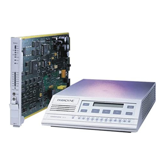
Standalone Model 3910 4-Wire/2-Wire Modem The standalone Model 3910 modem (Figure 1-1) is capable of either 4-wire/2-wire leased-line or dial operation. The modem is controlled using either AT commands or the diagnostic control panel (DCP). The DCP consists of a liquid crystal display (LCD), three function keys, four directional keys, and a row of 13 LED status indicators. -
Page 18: Model 3911
Model 3911’s faceplate has 16 LED status indicators for displaying modem activity and an audio speaker jack for the carrier’s optional speaker. The Model 3911 modem’s rear has two edge card connectors that mount into a connector plate located on the rear of the carrier. This connector plate has two DB-25-S connectors, one providing an EIA-232-D DTE interface and one for future functionality. -
Page 19: Government Requirements And Equipment Return
The Model 3911 derives ac power from the COMSPHERE 3000 Series Carrier’s backplane, which is a common bus to all devices installed in the carrier. The user interface to any Model 3911 is through the shared diagnostic control panel (SDCP), an optional feature which operates in a manner similar to the DCP on the Model 3910. - Page 20 Via the Internet: Visit the Paradyne World Wide Web site at http://www.paradyne.com Via Telephone: Call our automated call system to receive current information via fax or to speak with a company representative.
- Page 21 Canada NOTICE TO THE USERS OF THE CANADIAN PUBLIC SWITCHED TELEPHONE NETWORK The Canadian Department of Communications label identifies certified equipment. This certification means that the equipment meets certain telecommunications network protective, operational and safety requirements. The Department does not guarantee the equipment will operate to the user’s satisfaction.
-
Page 22: Technical Specifications
Leased-Line Modulations: Paradyne V.32terbo (19200, 16800 bps) ITU-T V.32bis (14400, 12000, 9600, 7200, 4800 bps) ITU-T V.32 (9600, 4800 bps) Paradyne Trellis Multipoint (19200, 14400, 9600, 7200, 4800, 2400 bps) ITU-T V.22bis (2400 bps) ITU-T V.27bis (4800, 2400 bps) ITU-T V.33 (14400, 12000 bps) ITU-T V.29 (9600, 7200, 4800 bps) - Page 23 4 watts (typical, each card) (Speaker consumption is approximately 1 watt at high volume.) 2.5 pounds (1.14 kg) Model 3910 (without power supply) 1.0 pounds (0.45 kg) Model 3911 2.1 inches (5.4 cm) Model 3910 7.1 inches (18.1 cm) Model 3911 7.6 inches (19.4 cm) Model 3910...
- Page 24 COMSPHERE 3900 Series Modems Technical Specifications for 391x Series Modems Specifications DATA RATES Leased Line Dial Line ERROR CONTROL DATA COMPRESSION 1-10 Table 1-1 (3 of 3) Description 19200, 16800, 14400, 12000, 9600, 7200, 4800, 2400 1200 bps 19200, 16800, 14400, 12000, 9600, 7200, 4800, 2400, 1200, 600, 300 bps ITU-T V.42 MNP 4-2...
-
Page 25: Modem Installation
One 8-position, 8-wire modular cord (in selected models) For the carrier-mounted model Installation instructions Model 3911 modem Rear connector plate with two DB-25-S edge card connectors If any hardware components are damaged, notify your service representative. Return equipment using the procedures described in Government Requirements and Equipment Return in Chapter 1, Introduction. -
Page 26: Model 3910 Modem Installation
One of the following modular leased or dial network interfaces: — JM8 for leased-line applications. — RJ11C for dial permissive applications. The following customer-supplied equipment is required for the installation of a Model 3911 modem: A COMSPHERE 3000 Series Carrier. -
Page 27: Model 3910 Rear Panel And Power Supply
Connecting Cables to the Model 3910 Modems Figure 2-1 shows how Model 3910 modems are connected to certain TELCO jack types using the appropriate cables. For pin assignments, refer to Appendix C, Pin Assignments. LEASED DIAL 8-POSITION, 8-CONDUCTOR PLUG FOR LEASED-LINE NETWORK OPERATION... -
Page 28: Dte Connection
COMSPHERE 3900 Series Modems DTE Connection Use the following procedures to connect the EIA-232-D cable from the modem to the DTE: 1. Make sure the modem’s rear panel power switch is OFF. 2. Connect the DB-25-P (plug) connector on the cable to the DB-25-S (socket) connector labeled DTE (Figure 2-1) on the modem’s rear panel. -
Page 29: Network Management System Connection
Network Management System Connection For the Model 3910, use the following procedures to connect the modem to the network management system interface: 1. Insert the sub-miniature, 4-conductor modular plug of the 3600 Hubbing Device into the jack labeled NMS (Figure 2-1). Refer to Document Number, 3610-A2-GZ45, 3600 Hubbing Device Feature Number 3600-F3-300, Installation Instructions, for a description of the 3600 Hubbing Device. -
Page 30: Selecting Factory Configuration Options
COMSPHERE 3900 Series Modems Selecting Factory Configuration Options After the modem passes the power-up self-test, configure it for operation using one of the six factory preset configurations. The 391x Series modems have six factory preset templates that contain the most commonly used configuration options (straps) for Synchronous Leased (Answer or Originate), Asynchronous Leased (Answer or Originate), Trellis Multipoint (Control or Tributary), Asynchronous Dial, Synchronous Dial, and UNIX Dial hardware network configurations. - Page 31 6. Press the the corresponding function key to select your choice. (Saving configuration options to the Active (Saved) configuration area automatically saves them to the Active (Operating) configuration area.) The LCD displays Command Complete. 7. The modem is now configured with the selected factory template. Press the return to the Top-Level menu.
- Page 32 COMSPHERE 3900 Series Modems To change a factory template using AT commands, perform the following steps. For more information on changing factory templates using AT commands, refer to Chapter 14, AT Command Set and S-Registers. 1. Use the AT&F&W command to load the appropriate factory configuration to the appropriate storage area.
-
Page 33: Removing And Replacing Model 3910 Modems
128 compatible modems. The installation of a Model 3911 varies slightly if an SDCP is installed on the front of the carrier. To install a Model 3911 modem into the carrier without an SDCP, perform the following steps: 1. -
Page 34: Installing A Model 3911 Modem
“click” is heard. 3. If the carrier is ON, the Power LED on the faceplate of the 3911 lights. After several seconds the modem completes its power-up self-test, in which all faceplate LEDs light. -
Page 35: Circuit Pack Lock
5. Press the modem. The LCD displays the Top-Level menu for the selected modem. In addition, the Front Panel LED on the modem’s faceplate and the OK LED on the SDCP light. 6. Once you have determined that the modem is installed properly and completed its power-up self-test, rotate the circuit pack lock until it covers the faceplate latch (Figure 2-3) and tighten the retention screw on the circuit pack lock. -
Page 36: Removing And Replacing Model 3911 Modems
Model 3911 in an antistatic bag when it is removed from the carrier. It is not necessary to power down the carrier to remove and replace a Model 3911 modem. Perform the following steps: 1. Rotate the circuit pack lock until the release tab is exposed. -
Page 37: Dcp Operation
(SDCP), an optional feature, used with the Model 3911 installed into a COMSPHERE 3000 Series Carrier. Both DCPs have a two-line, 32-character liquid crystal display (LCD) and keypad through which Top-Level menu branches are... -
Page 38: Model 3910 Dcp
The shared diagnostic control panel (SDCP), Figure 3-2, is used to manage carrier-mounted Model 3911 modems. The faceplate of the Model 3911 contains status indicators that monitor the operation of the modem. After the SDCP is connected to the modem, the Front Panel indicator of the selected modem lights to show that the modem is connected. -
Page 39: Status Indicators
All of the status indicators on the Model 3910 appear on the DCP (Figure 3-1), whereas the status indicators for the carrier-mounted Model 3911 are located on the Model 3911’s faceplate, the SDCP, and the SDU faceplate (Figure 3-2). - Page 40 The standalone Model 3910 modem’s DCP has 13 light-emitting diodes (LEDs), and the carrier-mounted Model 3911 has 16 LEDs. These LEDs are listed and described in Table 3-1. LEDs specific to one model type have the appropriate model number shown in the table.
-
Page 41: Diagnostic Control Panel Operation
The SDCP LEDs are listed and described in Table 3-2. Label Color green Power is ON and the modem is capable of operating. Alarm The modem has detected a problem with its operation. For example, the modem failed a self-test. BckUp yellow The modem, originally configured for leased-line operation, is now operating on... - Page 42 COMSPHERE 3900 Series Modems LCD Display The LCD consists of a top line and bottom line, with each displaying a maximum of 16 characters at a time. If more information is available on the LCD than what is currently displayed, an indicator appears in the top right or bottom right-hand corner of the LCD. Use the key to scroll in the indicated direction to display more selections onto the LCD.
- Page 43 Function keys select the LCD choice that appears above the function key; they are labeled F1, F2, and F3. If a selection spans more than one function key, then any of those keys choose that selection. Key (Model 3911 only) Select Select used to connect the SDCP to a modem in a specific slot in the carrier.
-
Page 44: Menu Structure
COMSPHERE 3900 Series Modems Menu Structure The menu tree is a hierarchical structure used to display functions that configure and control local and remote 391x Series modems. It is accessed via the DCP and is shown in Appendix A, Menu Tree. - Page 45 Status Message Normal Leased:MR* Operation Idle:MR* OnLine:MR* EC** Ring Indicate Test:MR* Alarm*** Make Busy Power On Fail SelfHealth Fail Call Setup Off Hook Dialing Remote Ring Training**** EC Negotiating Dial Backup or Standby: MR* Leased Backup DialBckUp:MR* Backup:MR* EC** Standby:MR* EC** * MR.
- Page 46 COMSPHERE 3900 Series Modems Status Message Call Failure Busy Signal Delayed Number [ Dial Line in Use Forbidden Number [ Invalid Number Line Occupied[[ No Answer Tone No Dial–DTR No Dial–Test No Dial Tone No Quiet Answer Ringback Timeout Trunk Busy Wrong Call * MR.
- Page 47 Status Message Call Disconnect ATH Disconnect Bad Lines Disc No Carrier Disc Disconnect EC Disconnect Inv Rate Disc LnCurrnt Disc LongSpace Disc NoData Disc Disconnecting RmtCmnded Disc Talk Mode Firmware DownldOnly Download Mode Result Frmware Upgrade RemClone Failed Firmware Remote Clone Download Result Cont.
- Page 48 COMSPHERE 3900 Series Modems Messages listed in Table 3-4 are common operational messages that occur during modem operation. These messages normally appear on the second line of the LCD. Common Operational Message Please Wait... A command to a local device takes more than two seconds to complete. Command Sent...
- Page 49 The Top-Level menu’s main branches appear on the LCD in the order of Status, Configure, PList, Control, Test, SubHS, Call Setup, Talk/Data, Security, and Remote. These branches are described in detail in Chapters 4 through 13. Quick Configuration Display The Quick Configuration display indicates the basic operational characteristics of the modem. To access the Quick Configuration display from the Top-Level display, press the 3910-A2-GN32-40 Leased:19.2...
- Page 50 COMSPHERE 3900 Series Modems The modem’s Quick Configuration information appears on the LCD’s bottom line. ffff To exit the Quick Configuration function and return to the Top-Level menu, press the key. 3-14 Displays the network position of the modem. The letter C indicates this is a control modem, and T indicates this is a tributary modem.
-
Page 51: Status Branch
Overview The Status branch of the Top-Level menu allows you to view the current status of the leased-line or dial connection, the identity (for example, serial number and model number) of your equipment, and the DTE interface. Configure PList Status DeviceHS Identity Major... - Page 52 COMSPHERE 3900 Series Modems To access Status from the Top-Level menu, select Status. Device Health and Status (DeviceHS) DeviceHS provides a ‘‘snapshot” of current modem alarms which are active at the time the DeviceHS function is selected. To access DeviceHS from the Status branch, make the following selection: Select DeviceHS.
- Page 53 Type Message Major Device Failure Facility Fault Streaming DTE Access Security Minor VF Threshold DTE Alarm Rate Fallback Status Subtree Truncate Test Mode Disabled On Dial Backup FW Downloading On Lease Backup Primary Line Bad Backup Line Good Data Blocked PSTN Test Fail 3910-A2-GN32-40 Table 4-1...
- Page 54 Health and Status Messages Indicates The modem is in a Make Busy condition. (Model 3911 only) The modem installed in a COMSPHERE 3000 Series Carrier has been switched to a service line. The modem’s dial hold time has been shortened.
- Page 55 VF displays the condition of the leased or dial connection. To access VF from the Status branch, make the following selection: Select VF. If the modem is receiving a signal, the signal quality appears on the LCD’s bottom line. Press the key to scroll and view the receive signal level, signal-to-noise ratio, near end echo level, far end echo level, far end echo delay, and echo frequency offset.
- Page 56 Serial number is an 8-digit number that identifies the modem. Model number is an alphanumeric number that identifies the modem as either a Model 3910 or Model 3911 modem. Firmware revision level is an alphanumeric number that identifies the level of firmware loaded in the modem.
- Page 57 DTE displays the state and/or activity of the following interface leads: LSD, DTR, DSR, Tst, TXD, RXD, RTS, and CTS. The interface leads status is updated every 5 seconds. To access DTE from the Status branch, make the following selections: Press the The activity and state of the modem’s DTE signal appear on the LCD’s bottom line.
- Page 58 COMSPHERE 3900 Series Modems To access Backup from the Status branch, make the following selection: Press the Select Backup. The configuration of the current operating line facility (either APL primary or backup) appears (Refer to Table 4-2). Press the This screen displays the configuration and condition of the inactive line facility (either APL primary or backup).
- Page 59 Active Line Inactive Line 1st Screen Display 2nd Screen Display Line=Pri 4w APL Bckup:2wAPL=XXXX Line=Pri 2w APL Bckup : Dial =(blank) Line=Bkup 2w APL Pri 4w APL =XXXX Line = Dial Backup Pri 2w APL =XXXX Line=Dial Only No second screen display.
- Page 60 COMSPHERE 3900 Series Modems Options The Options Status function displays all optional firmware features currently installed in the modem. If no firmware options are installed, None_Installed appears on the LCD. To access Options from the Status branch, make the following sections: Press the If optional features are installed in the modem, they appear on the LCD’s bottom line.
- Page 61 Press the To display sequence faults, select Display. The LCD displays the first sequence fault field. (Sequence fault fields range from 1 to 8 and are identified by a number in the upper right corner.) Press the The message Modem O.K. appears if no sequence faults have occurred. To remove sequence fault records from both the LCD and nonvolatile memory, select Clear.
- Page 62 COMSPHERE 3900 Series Modems This page intentionally left blank. 4-12 September 1998 3910-A2-GN32-40...
-
Page 63: Dcp Configuration
Overview After installing a 391x Series modem, its software configuration options must be set using either the diagnostic control panel (DCP) or the AT command set. This chapter describes how to access and use the Configure branch of the Top-Level menu via the DCP. The Configure branch accesses the Edit Area which is a work space where you view and change any configuration options (straps). -
Page 64: Dial
COMSPHERE 3900 Series Modems Figures 5-1 and 5-2 graphically display the interaction between the edit area and configuration areas as viewed from the perspective of the DCP and the AT command set. CONTENTS OF Active (Saved) ARE AUTOMATICALLY COPIED TO Active (Operating) WHEN A SAVE IS COMMANDED VIA THE DCP, ON A RESET, OR ON POWER-UP. -
Page 65: At Command Configuration Process
Active (Saved) (ATZ0, ATZ3) NOTE ON POWER-UP, Active (Saved) IS LOADED TO Active (Operating) Active (Saved) (AT&W0) Figure 5-2. AT Command Configuration Process 3910-A2-GN32-40 Customer1 Customer2 (ATZ1) (ATZ2) S Sync S Async S TMp S Async Dial LOAD Active (Operating) USING ATZ OR AT&F COMMAND Active (Operating) -
Page 66: Configure Branch
COMSPHERE 3900 Series Modems Configure Branch The Configure branch of the Top-Level menu contains all of the modem’s configuration options (straps) which determine how the modem operates. These configuration options are accessed by scrolling down and across various levels of the Configure branch. Status PList Configure... - Page 67 The Configure branch consists of the following three levels: Ld EditArea frm. Allows the selection of the Active (Operating), Active (Saved), Customer 1, Customer 2, and Factory configuration areas. Choose Function. Allows you to make changes (Edit) to existing configuration options or write (Save) these changes to either the Active (Saved), Customer 1, or Customer 2.
- Page 68 COMSPHERE 3900 Series Modems Select Sync_Leased. Select Answer. Select Edit. Scroll across the LCD and select the Misc configuration options group. Ld Fact Preset: > Sync_Leased Choose Mode: Answer Originate Choose Function: Edit Save Edit StrapGroup: > DTE_Interface Edit StrapGroup Test Misc September 1998...
- Page 69 Select Nxt until RemAccssPasswrd appears. Select the F2 ( " ) key to increment password values. Press the Continue this sequence until you have entered the new password value. 3910-A2-GN32-40 StrapsWhenDisc > No_Change RemAccssPasswrd: "00000000 RemAccssPasswrd: "10000000 RemAccssPasswrd: "10000000 key to move the cursor to the next position. RemAccssPasswrd: "12345678 September 1998...
- Page 70 COMSPHERE 3900 Series Modems To save the new password to a configuration area, make the following selections: Press the Select Save. Select a configuration area (Active (Saved), Customer 1, or Customer 2) to save the changes. Select the branch. Summary When using the DCP to edit configuration options, keep the following in mind: Nxt has two functions.
-
Page 71: Configuration Tables
Configuration Tables The modem’s configuration options are arranged into nine groups based on functionality: DTE Interface (Table 5-1), DTE Dialer (Table 5-2), Line Dialer (Table 5-3), Dial Line (Table 5-4), Leased Line (Table 5-5), V.42/MNP/Buffer (Table 5-6), Test (Table 5-7), Misc (Table 5-8), and Security (Chapter 12). - Page 72 COMSPHERE 3900 Series Modems Async/Sync Mode: Sync Nxt Sync Async Asynchronous/Synchronous Mode. Determines whether the modem operates in Asynchronous mode or Synchronous mode. If the AT command set is enabled and this configuration option is set to Sync, then the modem operates in Async mode when offline. For Async Dial, Async Leased and UNIX Dial, Async is the factory default.
- Page 73 Asyn Parity Bit: None Nxt None Even Odd Mark Space This configuration option only appears if Async/Sync Mode is configured for Async. Asynchronous Parity Bit. Determines the type of asynchronous parity bit. The parity of the DTE must match the parity of the modem. Parity options include None, Even, Odd, Mark, or Space. H None No parity bit is used.
- Page 74 COMSPHERE 3900 Series Modems DTR Action: Ignore Nxt Ignore Stndrd_RS232 CntrlsOnHook CntrlsTxMute Data Terminal Ready Action. DTR is a signal from the DTE to the modem indicating that the DTE is connected and ready for operation. H Ignore Modem assumes DTR is always ON. This is used when the DTE does not provide DTR. H Standard RS232 Allows the DTE to control DTR to the modem as specified in EIA-232-D and ITU-T V.24 specifications.
- Page 75 DSR Control: Stndrd_RS232 Nxt Stndrd_RS232 Forced_On WinkWhenDisc Follows_DTR On_Early Delay_ToData Data Set Ready Control. DSR is a signal from the modem to the DTE indicating the modem is connected and ready for operation. H Standard RS232 Allows the modem to control DSR to the DTE. The modem raises DSR when it begins the handshake process.
- Page 76 COMSPHERE 3900 Series Modems RTS Action: Stndrd_RS232 Nxt Stndrd_RS232 Ignore Sim_Cntl_Car Cntl_Car Request-to-Send Action. RTS is a signal from the DTE indicating the DTE has data to send. H Standard RS232 Allows the DTE to control RTS to the modem in normal EIA-232-D operation. RTS must be ON for the DTE to transmit to the modem.
- Page 77 CTS Control: Stndrd_RS232 Nxt Stndrd_RS232 Forced_On WinkWhenDisc Follows_DTR Follows_RTS40 Clear-to-Send Control. CTS is a signal from the modem to the DTE indicating that it can accept data from the DTE. H Standard RS232 In Synchronous mode, forces the state of CTS to follow the state of RTS in normal EIA-232-D operation.
- Page 78 COMSPHERE 3900 Series Modems LSD Control: Stndrd_RS232 Nxt Stndrd_RS232 Forced_On WinkWhenDisc Follows_DTR Sim_Cntl_Car =DTR/DiscOFF Line Signal Detect Control. LSD is a signal indicating that the carrier signal is being received from the remote modem. It is normally turned OFF to the DTE when the power level of the received carrier signal drops below the carrier detect threshold.
- Page 79 TX Clock Source: Internal Nxt Internal External RXC_Loop This configuration option only appears if Async/Sync Mode is configured for Sync. Transmit Clock Source. Determines the source of timing for synchronous data transmitted from the modem to the analog channel. H Internal The transmit data’s clock source is derived from the modem’s internal clock.
- Page 80 COMSPHERE 3900 Series Modems CT111_Rate Cntl: Disable Nxt Disable Fallback1 Fallback2 CT111 Rate Control. Allows the DTE to control modem rate via Pin 23 of the EIA-232-D interface. This configuration option determines the effect of the DTE Rate control signal. CT111 is also known as CH on the EIA-232-D interface.
- Page 81 Extend Main Ch.: Disable Nxt Disable Enable Primary data can only be extended one link. Extend Main Channel. This configuration option supports extended diagnostics. Specifies whether there is main (primary) channel connectivity between the modem’s DTE ports and the DTE ports of modems one level below (downstream) or above (upstream) in the diagnostic network.
- Page 82 COMSPHERE 3900 Series Modems DTE Dialer Type: Disable Nxt Disable AT V25bis_Async V25bis_Bsync V25bis_HDLC DTR=Direct1 AT&T_Exclusv Data Terminal Equipment Dialer Type. Identifies to the modem the type of dialing method and protocol used by the DTE. H Disable Disables any type of DTE dialing method. Dialing can only be performed using the DCP’s Dial command or attached telephone.
- Page 83 AT Escape Char: 043 ASCI Nxt " 043 ASCI This configuration option only appears if DTE Dialer Type is configured for AT. AT Escape Character. The escape sequence (+++) allows you to move from Data mode to Command mode. Use the AT Originate (ATO) command to return to Data mode. The ASCII value of the escape character (43 ASCII) can be set to any ASCII value from 0 ASCII to 255 ASCII.
- Page 84 COMSPHERE 3900 Series Modems CarriageRtn Char: 013 ASCI Nxt " 013 ASCI This configuration option only appears if DTE Dialer Type is configured for AT. Carriage Return Character. Allows you to change the ASCII character used to terminate an AT command to any ASCII value from 0 to 127.
- Page 85 ExtendResltCode: Enable Nxt Enable Disable Add/EC Add/V42,MNP Use_DTE_Rate This configuration option only appears if DTE Dialer Type is configured for AT. Extended Result Codes. Informational messages such as VF data rate and Error Control are displayed with the result codes. (For a list of Extended Result Codes, refer to Table 14-1 in Chapter 14, AT Commands and S-Registers.) H Enable NO DIALTONE, BUSY, NO ANSWER, and CONNECT xxxx (xxxx = VF data rate) appear along...
- Page 86 COMSPHERE 3900 Series Modems AT Cmnd Mode: Normal Nxt Normal No_ERROR NoStrapOrERR This configuration option only appears if DTE Dialer Type is configured for AT. AT Command Mode. Determines how the modem responds to valid and invalid AT commands. H Normal Allows normal operation of the AT command set.
- Page 87 Line Dialer The Line Dialer configuration options establish parameters used by the modem to answer or originate calls. Table 5-3 shows each Line Dialer configuration option as it appears on the LCD, with the Sync Leased factory default setting (the default value if the modem is just being installed) shown following the colon ( : ) on the first line and with all available selections listed on the second line.
- Page 88 COMSPHERE 3900 Series Modems Blind Dial Pause: 2sec Nxt 2sec 4sec 6sec 8sec 10sec 20sec This configuration option only appears when Dial Tone Detect is configured for Disable. Blind Dial Pause. Determines how long the modem waits before dialing a telephone number when Dialtone Detect is disabled.
- Page 89 Line Crnt Disc: Enab(>8msec) Nxt Enab(>8msec) Enab(>90msec) Disable This configuration option does not appear on Models 3910-A1-401 and 3911. Line Current Disconnect. Determines the modem’s response to short interruptions of line current. The loss of line current is one method of disconnecting a call.
- Page 90 Auto Make Busy: Disable Nxt Disable Enable This option is only valid with the Model 3911 and does not appear on the Model 3910’s LCD. Automatic Make Busy. Forces the modem to go off-hook under the following conditions: if a local analog loopback is performed, a self-test is performed, or if the modem is switched to the service line.
- Page 91 NOTE: This configuration option should only be used when the modem is located behind a user’s Private Branch Exchange (PBX). For 3911 modems, the Make Busy Network Interface Modules (NIMs) must be installed on the COMSPHERE 3000 Series Carrier. Refer to the COMSPHERE 3000 Series Carrier, Installation Manual.
- Page 92 COMSPHERE 3900 Series Modems Dial Line The Dial Line configuration options are used to configure the modem for operation over dial lines. Table 5-4 shows each Dial Line configuration option as it appears on the LCD, with the Sync Leased factory default setting (the default value if the modem is just being installed) shown following the colon ( : ) on the first line and with all available selections listed on the second line.
- Page 93 Nxt Disable 2400 1200 This configuration option is ignored unless Dial Line Rate is 4800(V32b). V.32bis Override. Activates the Paradyne Point-to-Point Diagnostic 2400 bps or 1200 bps modulation. Allows the modem to use a non-standard, point-to-point modulation capable of secondary channel diagnostics while running at 2400 bps or 1200 bps.
- Page 94 COMSPHERE 3900 Series Modems V22b Guard Tone: Disable Nxt Disable 550Hz 1800Hz This configuration option only appears when Dial Line Rate is configured for V.22bis or V.22 data rate, or when V.32bis Automode is configured for Enable. V.22bis Guard Tone. Determines whether the V.22bis guard tone is disabled, set to 550 Hz, or set to 1800 Hz.
- Page 95 Leased Line The Leased Line configuration options only appear when the Sync Leased factory preset template is selected. They are used to configure the modem for operation over leased lines. Table 5-5 shows each Leased Line configuration option as it appears on the LCD, with the Sync Leased factory default setting (the default value if the modem is just being installed) shown following the colon ( : ) on the first line and with all available selections listed on the second line.
- Page 96 COMSPHERE 3900 Series Modems LeasedLine Rate: 19200(V32t) Nxt 19200(V32t) 16800(V32t) 14400(V32b) 12000(V32b) 9600(V32b) 7200(V32b) 4800(V32b) 19200(TMp) 14400(TMp) 9600(TMp) 7200(TMp) 4800(TMp) 2400(TMp) 2400(V22bis) 14400(V33) 12000(V33) 9600(V29) 7200(V29) 4800(V29) 4800(V27bis) 2400(V27bis) Leased-Line Rate. Determines the modem’s data rate and modulation scheme for operation on leased lines. NOTE: Certain changes to this configuration option will cause the modem to reset.
- Page 97 Nxt Disable 2400 1200 This configuration option is ignored unless Leased-Line Rate is 4800(V32b). V.32bis Override. Activates the Paradyne Point-to-Point Diagnostic 1200 bps or 2400 bps modulation. Allows the modem to use a non-standard, point-to-point modulation capable of secondary channel diagnostics while running at 1200 bps or 2400 bps.
- Page 98 COMSPHERE 3900 Series Modems AutoDialStandby: Disable Nxt Disable 15min 1hr 4hr Test(2min) Adv 15min Adv 30min Adv 1 hr TestAdv2min This configuration option is not available if the LeaseLine Rate is configured for TMp and the NetworkPosition is configured for Control. Automatic Dial Standby.
- Page 99 DCP Configuration Table 5-5 (5 of 6) Leased Line Configuration Options V27bis Train: Short Nxt Short Long This configuration option is only available if Leased-Line Rate is configured for V27bis. V.27bis Train. Controls the train time for V.27bis operation. The AT command is S-Register S70=n, where n is 0 for Short and 1 for Long. V29 TrainOnData: Disable Nxt Disable Enable This configuration option is only available if Leased-Line Rate is configured for V29.
- Page 100 COMSPHERE 3900 Series Modems Lease_Lookback: Disable Nxt Disable Enable Lease Lookback. While operating on backup lines, this configuration option allows the modem to test the primary 4-wire leased lines for connectivity by detecting line energy across the normal line bandwidth. This test of the primary lines will not interrupt the data flow on the backup lines.
- Page 101 Err Contrl Mode: V42/MNPorBfr Nxt V42/MNPorBfr V42/MNPorDsc MNP_or_Buffr MNP_or_Disc BufferMode DirectMode LAPM_or_Disc LAPM_or_Bufr This configuration option is only available if Async/Sync Mode is configured for Async. Error Control Mode. Determines the type of error control used by the modem. In most cases, V42/MNPorBfr is the best choice.
- Page 102 COMSPHERE 3900 Series Modems Err Contrl Mode (Continued) Nxt V42/MNPorBfr V42/MNPorDsc MNP_or_Buffr MNP_or_Disc BufferMode DirectMode LAPM_or_Disc LAPM_or_Bufr The AT command for Buffer Mode is \N0. The AT command for Direct Mode is \N1. The AT command for MNP or Disconnect is \N2. The AT command for MNP or Buffer is \N3.
- Page 103 EC Negotiat Bfr: Disable Nxt Disable Enable Disab&Switch This configuration option is only available if Async/Sync Mode is configured for Async, and Error Control Mode is configured for V42/MNPorBfr, MNP_or_Buffr, or LAPM_or_Bufr. Error Control Negotiate Buffer. Determines if the answering modem buffers the data that it received from the remote modem during an interval in which the modem attempts to establish a connection using error control.
- Page 104 COMSPHERE 3900 Series Modems Flw Cntl of DTE: CTS_to_DTE Nxt CTS_to_DTE Disable XON/XOFF This configuration option is only available if Async/Sync Mode is configured for Async, and Error Control Mode is not configured for DirectMode. Flow Control of DTE. Determines how the modem controls the flow of data from the DTE. H CTS to DTE Method of flow control in which the modem raises and lowers its CTS interface lead to indicate when the DTE should start and stop sending data.
- Page 105 XON/XOFF Psthru: Disable Nxt Disable Enable This configuration option is only available if Async/Sync Mode is configured for Async, and Flow Control of Modem is configured for XON/XOFF. XON/XOFF Passthrough. Considers an XON/XOFF character as data and passes it on to the remote modem.
- Page 106 COMSPHERE 3900 Series Modems Break Buffr Ctl: Keep_Data Nxt Keep_Data Discard_Data This configuration option is only available if Async/Sync Mode is configured for Async, and Error Control Mode is not configured for DirectMode. Break Buffer Control. Determines if data stored in the modem’s buffer is saved or discarded when the DTE issues a break sequence.
- Page 107 BuffrDiscDelay: 10sec Nxt 10sec Disable 60sec This configuration option is only available if Async/Sync Mode is configured for Async, and Error Control Mode is not configured for DirectMode. Buffer Disconnect Delay. Determines how long the modem continues to transmit data stored in its buffers when the modem is commanded to disconnect by a locally attached DTE.
- Page 108 COMSPHERE 3900 Series Modems Test The Test configuration options determine specifics, such as the duration of a test, for the various diagnostic tests available to the modem. Table 5-7 shows each Test configuration option as it appears on the LCD, with the Sync Leased factory default setting (the default value if the modem is just being installed) shown following the colon ( : ) on the first line and with all available selections listed on the second line.
- Page 109 Test Timeout: Disable Nxt Disable 30sec 60sec 240sec Test Timeout. Determines how long a test runs before aborting. H Disable Allows a test to run indefinitely. H 30, 60, or 240 seconds Allows the test to run for 30 seconds, 60 seconds, or 240 seconds. The AT command is S-Register S18=n, where n is 0 for Disable and 1 to 255 seconds.
- Page 110 COMSPHERE 3900 Series Modems Misc The Miscellaneous configuration options determine specifics for various functions, including network management parameters and remote modem access. Table 5-8 shows each Misc (Miscellaneous) configuration option as it appears on the LCD, with the Sync Leased factory default setting (the default value if the modem is just being installed) shown following the colon ( : ) on the first line and with all available selections listed on the second line.
- Page 111 Speaker Volume: Medium Nxt Medium Low High Speaker Volume. Controls the level of speaker volume. NOTE: Speaker Volume can also be temporarily set using the Control branch; however, a reset or power cycle will restore the modem to the Speaker Control and Speaker Volume configuration option settings.
- Page 112 NOTE: This configuration option is only applicable for leased-line network management applications. For the Model 3910, Tributary is the factory default. For the Model 3911, Control is the factory default. The AT command for Tributary is S74=0. The AT command for Control is S74=1.
- Page 113 Diag Connection: Modem(DC) Nxt Modem(DC) NMS(CC) Disable This configuration option is not available if the LeaseLine Rate is configured for TMp and the NetworkPosition is configured for Tributary. Diagnostic Connection. Allows the configuration of the serial diagnostic port of the modem to be either a diagnostic channel that is connected to another modem (DC), or a control channel that is connected to a network management device (CC).
- Page 114 COMSPHERE 3900 Series Modems This page intentionally left blank. 5-52 September 1998 3910-A2-GN32-40...
-
Page 115: Poll List Branch
Overview The Poll List function is not available on Point-to-Point control modems or Multipoint Tributary modems. The Poll List (Plist) branch of the Top-Level menu allows you to identify downstream modems in order to support health and status polling and download broadcasting. The maximum number of devices is 16 on the secondary channel and 64 on the diagnostic channel. - Page 116 COMSPHERE 3900 Series Modems To access PList from the Top-Level menu, make the following selections: Press the Within a network link, a control modem can communicate with a tributary modem by using the tributary modem’s network management address for polling functions. Each tributary modem must have a different network management address.
- Page 117 If there are modems in the poll list when you select Display, yyyyyy Select Nxt to scroll through the entries in the Active or Skip poll lists. To exit this function and remain in the PList Display branch, press the return to the Top-Level menu, press the Clear The Clear function does not appear in Remote mode.
- Page 118 COMSPHERE 3900 Series Modems Press the Change allows you to add modems to the Active poll list (Active), delete modems from both Active and Skip poll lists (Delete), and move modems from the Active to the Skip poll list. To implement Change, select the appropriate function (Active, Delete, or Skip). (For Skip, you will need to press the The function field (yyyyyy) displays the function you selected (Active, Delete, or Skip).
- Page 119 The Add function does not appear in Remote mode or on control modems. Add allows you to add the tributary modem to a control modem’s poll list. This function should be initiated from only one tributary modem at a time. To access Add from the Plist branch, make the following selections: Press the The message Command Complete appears on the LCD to indicate that the tributary modem...
- Page 120 COMSPHERE 3900 Series Modems Press the If an error message (OtherTestActive or Unable To Acquir) appears on the second line of the LCD, move up one level in the menu tree to clear the message and return to the PList Acquire branch.
-
Page 121: Control Branch
Status Configure PList Data_Stream Speaker Reset 3910-A2-GN32-40 Control Branch “Status” SubHS Call_Setup Test Control (3910 (3911 only) only) EIA_LEDs Make_Busy Service_Line RemoveMakeBusy DiscServiceLine September 1998 Tlk/Data Security Remote Download_Code VF_Thresh_Update (DownLoadSoftware) -
Page 122: Speaker
COMSPHERE 3900 Series Modems To access Control from the Top-Level menu, make the following selections: Press the Speaker Speaker allows you to make temporary adjustments to the modem’s speaker volume. Upon a reset, speaker volume returns to its configured setting. For more information on speaker settings, refer to Misc in Chapter 5, DCP Configuration.. -
Page 123: Reset
Reset Reset causes the modem to stop operation and perform a complete program restart. The modem begins the power-up test sequence that ends with the Top-Level menu displayed on the LCD. Configuration options stored in an Active (Saved) configuration area are copied to the Active (Operating) configuration area. -
Page 124: Eia Leds
COMSPHERE 3900 Series Modems If you want to disable the modem’s data stream, press the F2 key. When the message Command Complete appears, press the Press the F2 key again to enable the modem’s data stream. To exit this function and remain in the Control branch, press the the Top-Level menu, press the EIA LEDs Use the EIA LEDs function to change the port that controls the front panel LEDs. -
Page 125: Make Busy/Remove Make Busy
To exit this function and remain in the Control branch, press the the Top-Level menu, press the The Port1 interface is the only display allowed on the 3911 modem, therefore, the entire EIA LEDs branch is masked. Make Busy/Remove Make Busy The Make Busy function forces the modem off-hook so it cannot answer a call. -
Page 126: Service Line/Disconnect Service Line
A service line is an extra dial line connected to a COMSPHERE 3000 Series Carrier. This line is normally shared by up to eight Model 3911 modems installed in either Slots 1–8 or Slots 9–16. However, by daisy chaining the service-line connector of one Network Interface Module (NIM) to the service line of another NIM installed in the same carrier, you can permit all 16 modems to share one service line. -
Page 127: Download Software
Download Software The Download Software function sets parameters within the modem when transferring firmware to one or more modems or when receiving firmware upgrades from a locally attached PC-based controller. The latter is only performed by customer service personnel. There are two selections under Download Software: Clone Remote and To Local via DTE. Clone Remote is used to transfer an exact copy of the firmware currently stored in a 391x Series modem to either one or more remote 391x Series modems or one or more DC-attached 391x Series modems. - Page 128 COMSPHERE 3900 Series Modems Clone Remote in Point-to-Point Configurations Before using Clone Remote in point-to-point configurations, perform the following: Make sure the 391x Series modems have an established leased-line connection using either V.33, V.32terbo, V.32bis, V.32, or V.29 modulation (refer to the Leased Line section in Chapter 4) or a dial network connection using either V.32terbo, V.32bis or V.32 modulation (refer to Dial Line in Chapter 5, DCP Configuration).
- Page 129 From the Choose DLL Type screen, press the F2 to transfer an exact copy of the tributary modem’s firmware to the DC-connected control modem(s) using the Active Poll list. Proceed to Implementing a Clone Remote Operation on page 7-12, which follows the descriptions of multipoint cloning operations.
- Page 130 COMSPHERE 3900 Series Modems For Single download configurations, know the remote access password and the network management address of the remote tributary modem that will receive the download. Refer to the Misc section in Chapter 4 for a description of the remote access password (RemAccssPasswrd) configuration option and the network management address (NetMngmtAddress) configuration option.
- Page 131 After completing these actions, proceed to Implementing a Clone Remote Operation on page 7-12. Cloning a Multiple TMp Remote Press the F3 key to select Multiple Clone Remote. After completing this action, proceed to Implementing a Clone Remote Operation on page 7-12. Viewing Multiple TMp Clone Results From the Choose DLL Type screen, press the to view the results of the last multiple TMp clone operation.
- Page 132 COMSPHERE 3900 Series Modems Implementing a Clone Remote Operation The modem begins a transfer of its own program to the remote modem. This process takes the communication link out-of-service for several minutes depending on the data rate of the link. If the Clone Remote process is started and then interrupted, the remote modem is left in a partially programmed state in which its functional capabilities are limited to those required to initiate and complete another...
-
Page 133: Vf Thresholds Update
Access Disabled Password Invalid No Circuit After successful establishment of a Remote Cloning Download session, the following screens appear. As data banks are transferred, the local and remote LCD’s bottom line displays the status of the download process, and the number of records sent versus the total number of records for that bank. - Page 134 COMSPHERE 3900 Series Modems Press the VF_Thresh_Update. Select Edit. In the following example, the RSL High threshold is changed from 09 (– dBm) to 10. This example demonstrates VF threshold editing and saving. With the exception of Signal Quality, all VF thresholds may be modified in this manner.
- Page 135 Press the Select the F2 ( " ) key to change the number above the cursor ( 9 ) to 0. If you want to modify additional VF thresholds, select Nxt. To save the edited threshold(s): Press the Select Save. If the edited VF thresholds are valid, the Save command stores them into nonvolatile memory.
- Page 136 COMSPHERE 3900 Series Modems To correct the invalid VF threshold, press the Edit/Save/Reset screen. Select Reset to restore the original default values into memory. Repeat the Edit and Save procedure until the VF threshold(s) is valid and the Save completes successfully (Save Completed).
-
Page 137: Test Branch
Overview The Test branch of the Top-Level menu allows you to initiate various modem tests. Use these tests if you are having data communication problems, such as periodic character loss, random errors, or constant format errors. By the process of elimination, you can usually isolate the fault in your system. -
Page 138: Abort
COMSPHERE 3900 Series Modems To access the Test branch from the Top-Level menu, make the following selections: Press the Abort Abort ends any test that is in progress and brings the modem back to the normal mode of operation. Confirmation is provided by the Command Complete message. To access Abort from the Test branch, make the following selection: Select Abort. -
Page 139: Self
Self Self performs an internal self-test of the modem, which takes less than a minute to complete. The modem must be offline; otherwise, Invalid Command appears. When this test is run in Remote mode, it will cause the Remote mode session to be lost. The Remote mode session can be reestablished after the self-test is complete (usually one or two minutes). -
Page 140: Loc Analog Loop
COMSPHERE 3900 Series Modems Loc Analog Loop Loc Analog Loop performs a local analog loopback (ITU-T- V.54 Loop 3), Figure 8-1, that verifies modem operation as well as the connection between the DTE and modem. The modem must be offline and in Synchronous or Asynchronous Direct mode to perform this test, otherwise Invalid Command appears. -
Page 141: Rem Digital Loop
The message Started appears on the LCD, and the Test LED lights for the duration of the test. If Invalid Command appears on the LCD, another test is in progress. Select Abort to clear the current test and try again. If the Test Timeout configuration option is enabled, Test Timeout appears at the conclusion of the test. -
Page 142: Loc Digital Loop
COMSPHERE 3900 Series Modems Press the The message Started appears on the LCD, and the Test LED lights for the duration of the test. If Invalid Command appears on the LCD, another test is in progress. Select Abort to clear the current test and try again. -
Page 143: Pattern
Press the The message Started appears on the LCD and the Test LED lights. If Invalid Command appears on the LCD, another test is in progress. Select Abort to clear the current test and try again. If the Test Timeout configuration option is enabled, Test Timeout appears at the conclusion of the display. -
Page 144: Pattern Test And Digital Loopback Test
COMSPHERE 3900 Series Modems Figure 8-5. Pattern Test and Digital Loopback Test To access Pattern from the Test branch, make the following selections: Press the Figure 8-6. End-to-End Pattern Test Test: < Pattern key until Pattern appears. Select Pattern to start this test. Test:Pattern >... - Page 145 Test Branch BlksErrd=xxxxxxx displays the number of blocks of data found in error (block size is 1000 bits per block). BlksRcvd=xxxxxxx displays the total number of blocks of data received. The message NoSync appears as a value for BlksErrd while the modem’s receiver is synchronizing. The message OvrFlw appears as the value for BlksErrd if the counter overflows.
- Page 146 COMSPHERE 3900 Series Modems This page intentionally left blank. 8-10 September 1998 3910-A2-GN32-40...
-
Page 147: Sub-Network Health And Status Branch
Sub-Network Health and Overview The Sub-Network Health and Status (SubHS) function is not available on multipoint tributary modems or with certain modulations (V.29, V.33, V.22bis, and V.27bis). The SubHS branch of the Top-Level menu allows you to display alarm conditions in downstream modems. - Page 148 COMSPHERE 3900 Series Modems Press the If there are no modems in the multipoint poll list, the message Poll List Empty! appears on the second line of the LCD. When you select SubHS, yyyyyy Select Nxt to scroll through the entries in the poll lists. To exit this function and return to the Top-Level menu, press the key until SubHS appears.
-
Page 149: Call Setup Branch
Overview The Call Setup function is not available in TMp Control mode. For dial backup applications, the Call Setup branch of the Top-Level menu allows you to dial, disconnect, and answer telephone calls. For leased backup applications, the Call Setup branch allows you to switch between the primary leased line and the backup leased line. -
Page 150: Dial
COMSPHERE 3900 Series Modems To access the Call Setup branch from the Top-Level menu, make the following selections: Press the Dial For dial backup applications, Dial allows you to dial any telephone number stored in directory locations 1–24. Any telephone number dialed using the DCP must already exist in a directory location. -
Page 151: Disconnect
Once the directory location you want appears on the LCD, press the F2 or F3 key to dial the number. The Call Setup status Off Hook appears during the connection process. If the connection is successful, one of the Normal Operation status messages (Table 3-3 in Chapter 3, DCP Operation) appears on the LCD. -
Page 152: Answer
COMSPHERE 3900 Series Modems Answer For dial backup applications, Answer allows the modem to go off-hook, generate an answer tone, and begin the handshaking process with the calling modem. Use the Answer function when the Auto-Answer Ring Count configuration option is disabled. (Refer to Line Dialer in Chapter 5, DCP Configuration.) For leased backup applications, Answer allows the modem to begin the handshaking process with the remote modem. -
Page 153: Dial Standby/Return To Dial
Dial Standby/Return to Dial When the modem is operating in Dial Backup mode (DialBckUp), Dial Standby and Return to Dial allow the modem to switch back and forth between primary leased-line and primary leased-line backup operation while still maintaining the backup connection (Figure 10-1). Switching between backup and primary leased-line operation can be performed manually or automatically. -
Page 154: Change Directory
COMSPHERE 3900 Series Modems To access Dial Standby or Return to Dial from the Call Setup branch, make the following selections: Press the If the modem is operating in a Dial Backup mode, the Dial Standby function forces the modem to primary leased lines and the LCD displays the status message Command Complete. - Page 155 Press the Change_Directory. The phone number listed in directory location 1 appears. Select Nxt to display other directory locations. Entering Telephone Numbers and Dial Command Modifiers into Directory Locations The following example uses an empty directory location for describing how to enter a telephone number.
- Page 156 COMSPHERE 3900 Series Modems To save the number just entered, scroll to the next directory location by selecting Nxt. The number is now stored in nonvolatile memory. Table 10-1 describes what can be entered in directory locations. Dial command modifiers are parameters entered in the dial command string which specify how, when, and what number to dial.
-
Page 157: Directory Status (Does Not Appear In North America)
Directory Status (Does Not Appear in North America) Directory Status displays the status of each directory location. To access Directory Status from the Call Setup branch, make the following selections: Press the Directory_Status. Select Nxt to display other directory locations. The status of a directory location can be: No Number Allowed... - Page 158 COMSPHERE 3900 Series Modems This page intentionally left blank. 10-10 September 1998 3910-A2-GN32-40...
-
Page 159: Talk/Data Branch
On initial power-up, the modem is in Talk mode. When in Talk mode, the modem is disconnected and you are free to use the telephone. When in Data mode, the modem is connected and data can be transmitted or received. This function is not available for Model 3911 modems. Status Configure PList The following sections describe three uses of the Talk/Data function. -
Page 160: Manual Dialing When The Remote Modem Is Configured For Auto-Answer
(refer to Line Dialer in Chapter 5, DCP Configuration) must be set to Disable. This configuration option does not appear on Models 3910-A1-401 and 3911-B1-001. If you are originating a call using a telephone and the remote modem is configured for Auto-Answer, perform the following procedure. -
Page 161: Manual Dialing When The Remote Modem Is Configured For Manual Answer
(refer to Line Dialer in Chapter 5, DCP Configuration) must be set to Disable This configuration option does not appear on Models 3910-A1-401 and 3911-B1-001. If you are originating a call using a telephone and the remote modem is configured for Manual Answer, perform the following procedure. - Page 162 COMSPHERE 3900 Series Modems This page intentionally left blank. 11-4 September 1998 3910-A2-GN32-40...
-
Page 163: Dial Access Security
The Model 3910 can store a maximum of 20 passwords while the Model 3911 can store up to 3000 passwords. Control of security functions is established in the Security Configuration Options group which is located in the Configuration branch of the Top-Level menu. - Page 164 COMSPHERE 3900 Series Modems Originate Access Security Originate Access lets you control who can originate a call from a local modem via the AT command set. This is useful in LAN and modem pooling applications. With Originate Access security, a local user’s password is embedded in the AT dial command. If the password is valid, the user can dial out using this modem.
- Page 165 The following examples illustrate two ways to enter a VF-side password: ATDP5551234TW12345678# or ATDT5551234@12345678# Where: While pulse dial can be used to originate the call, DTMF tones must be used for the password. This can be accomplished by using the P and T modifiers appropriately.
-
Page 166: Security Branch
COMSPHERE 3900 Series Modems Combination of VF-Side and DTE-Side Passwords The previously described methods of password entry can be combined to provide two layers of security. In this case, the modems negotiate VF-side password entry prior to training. If successful, the modems connect and then prompt the originating user for a valid password. - Page 167 Set Access Ctrl Set Access Control allows you to configure critical parameters contained within the security database table that control dial access security. These parameters are protected by an Administrative Password, which is an 8-digit decimal number. Set Access Control contains the Edit Password Table, Set Answer Security, Set Originate Security, and Set Administrative Password security configuration groups.
- Page 168 Select Index allows a specific record to be retrieved. Index addresses range from 0001 to 0020 for the Model 3910 and from 0001 to 3000 for the Model 3911. The contents of this record can be viewed, edited, and saved.
- Page 169 Select Index appears. Press the F2 ( " ) key to increment index values. Press the Continue this sequence until the desired index appears, and then select Ent. If an index outside of the range is entered, the message Index Too Big appears. Choose an index from the database’s current index range.
- Page 170 COMSPHERE 3900 Series Modems H VF plus DTE Indicates that both layers of password entry are used with this index’s password. This location is configured so that the answering modem sends a prompt for the DTE-side password after receiving a valid VF-side password. This setting requires that the Set Answer Security option be set to VF_&_DTE.
- Page 171 Set Answer Sec Set Answer Security determines if dial access security is enabled or disabled. This method of inbound security is configured in the answering modem. Although this also appears under the Security Configuration Option group, it can only be changed from the Set Answer Sec LCD display in the Security branch.
- Page 172 COMSPHERE 3900 Series Modems Set Orig Sec Set Originate Security controls whether or not the modem can originate a call using AT commands when the dial access security feature is installed. This method of outbound security only applies to modems originating a call. To access Set Orig Sec from Set Access Ctrl, make the following selections: Press the Select Set_Orig_Sec.
- Page 173 Set Admin PsWd Set Administrative Password is used to change the Administrative Password value. The Administrative Password is an 8-digit decimal number that allows authorized users to enter the Access Security Control function. If this value is forgotten, then the only way to access any of the security functions is by selecting Reset Security.
- Page 174 COMSPHERE 3900 Series Modems Reset Security Reset Security is the second major function within the Security branch of the Top-Level menu. It erases all contents of the security database table and resets all index locations to Cleared. Two selections appear under Reset Security: Abort Security Reset and Erase All PassWords. Use Reset Security if you want to redo the entire security database table.
-
Page 175: Security Configuration Options
Security Configuration Options The Security Configuration Options group allows you to view and set dial access security parameters. This group is located in the Configuration branch of the Top-Level menu. Table 12-4 shows each Security configuration option as it appears on the LCD. The factory default value is shown after the colon ( : ) on the first line;... - Page 176 COMSPHERE 3900 Series Modems DTE Password Termination Character. Allows you to change the ASCII character used to indicate the end of a password or User ID entered by an originating user. This character can be set to any ASCII value from 0 to 127.
- Page 177 H VF & DTE The answering modem is enabled for security. The modems negotiate security using the VF-side password entry technique protocol. If successful, and the Password Type for this particular VF password is set for VF_&_DTE, a password is requested from the originating user. If successful, the modems connect and can pass data.
-
Page 178: Security Password Entry Techniques
COMSPHERE 3900 Series Modems Security Password Entry Techniques The previous sections described how to set up and configure your network for dial access security. Once configured and enabled, you must now supply a password to originate or answer a call. The following examples demonstrate how to enter an Answer Access security password string and an Originate Access password string. - Page 179 Originate Access Password An Originate Access password is entered by a local user to gain access to a local 391x Series modem. This password is embedded in the AT dial command and cannot be entered from the diagnostic control panel (DCP). The following example describes how to enter an Originate Access security password: TYPE: PRESS:...
-
Page 180: Database Table Examples
COMSPHERE 3900 Series Modems Database Table Examples The following examples illustrate possible database tables in which the password type is configured for VF Entry, DTE Entry or a combination of VF, DTE, and VF plus DTE Entry. These tables are shown for illustrative purposes only. Passwords shown are not representative of good password selections. - Page 181 Table 12-7 is an example of a security database table that uses a mixture of VF and DTE passwords. Security Database Table Using Both VF-Side and DTE-Side Passwords Index Password 1212 953246 46958373 32562682 1131 winter 1141 summer 1142 spring 1151 fall 1152...
- Page 182 COMSPHERE 3900 Series Modems This page intentionally left blank. 12-20 September 1998 3910-A2-GN32-40...
- Page 183 This page is self-supporting and can be removed for security reasons. Dial Access Security To clear the dial access security alarm light from the modem’s front panel, do the following: 3. Press the key to return to the Top-Level menu. 4.
- Page 184 COMSPHERE 3900 Series Modems This page intentionally left blank. 12-22 September 1998 3910-A2-GN32-40...
-
Page 185: Remote Branch
Overview The Remote branch of the Top-Level menu allows you to control the remote modem’s DCP using the local modem’s DCP. This function allows you to change configuration options and control test functions in a remote modem. Any changes made to configuration options while using the Remote branch are not saved until you exit the Remote branch. - Page 186 COMSPHERE 3900 Series Modems The following conditions must be met before using the Remote branch: A connection using either leased lines or the dial network must be established. The Access from the Remote configuration option must be enabled in the remote modem. In point-to-point networks, the Remote Access Password configuration option must be the same for both the local and remote modems.
- Page 187 For Trellis Multipoint (TMp) control modems, you must specify the network management address of a tributary modem. The following display does not appear in point-to-point or Trellis Multipoint tributary modems. The address field (xxx) displays the network management address of the modem to be accessed by the Remote function.
- Page 188 COMSPHERE 3900 Series Modems If operation over the secondary channel is desired, press any function key to select the secondary channel. Secondary channel only appears if using V.32terbo, V.32bis, V.32 or TMp modulation. If operation over the primary channel is desired, press the displays and press any function key.
- Page 189 If a connection is established but the wrong password is stored, the status message Password Invalid appears on the LCD. This configuration option must be enabled by the remote user. (Refer to the Remote Access Password configuration option in Table 5-8 of Chapter 5, DCP Configuration.) The Remote mode command displays Other Test Active if an Analog Loopback test is currently running.
- Page 190 COMSPHERE 3900 Series Modems This page intentionally left blank. 13-6 September 1998 3910-A2-GN32-40...
-
Page 191: At Command Set And S-Registers
AT Command Set and S-Registers Overview The AT command set provides an alternative method to the modem’s DCP for entering commands that control the operation and configuration of the 391x Series modems. This chapter discusses guidelines necessary to operate AT commands as well as listing the modifiers for all AT commands supported by the 391x Series modems. -
Page 192: Command Guidelines
COMSPHERE 3900 Series Modems Use the O command to return to Data mode from online Command mode. Enter the following command: TYPE: PRESS: Command Guidelines Review the following guidelines before using any AT Commands. The escape sequence ( + + + ) is used to enter online Command mode from Data mode. The asynchronous character format for the AT command set must be one of the following: —... - Page 193 Result Codes Table 14-1 lists all valid result codes for the 391x Series modem. Numbers Numbers CONNECT RING NO CARRIER ERROR CONNECT 1200* NO DIALTONE* BUSY* NO ANSWER* CONNECT 2400* CONNECT 4800* CONNECT 9600* CONNECT 12000* CONNECT 14400* CONNECT 19200** CONNECT 7200* CONNECT 16800** CONNECT 300*...
-
Page 194: At Command List
COMSPHERE 3900 Series Modems Numbers Numbers CONNECT 38400** CONNECT 19200/ EC** CONNECT 57600** FORBIDDEN DELAYED * Only appears when the Extended Result Codes configuration option is enabled. ** Only appears when the Extended Result Codes configuration option is set for Use_DTE_Rate. This displays the DTE data rate instead of the line rate. - Page 195 Command Repeat Last Command. Reexecutes last command string. (Not to be preceded with AT or followed by pressing the Return key.) Answer Mode. Goes off-hook and attempts to establish a connection without waiting for a ring. Dial. Begins the dialing sequence. The dial string n (modifiers and telephone number) is entered after the D command.
- Page 196 COMSPHERE 3900 Series Modems Command Dn (cont.) — Quiet answer. Wait for five seconds of silence after dialing the number. If the silence is not detected, the modem sends either a NO ANSWER result to the DTE. — Hook flash. This causes the modem to go on-hook for 0.5 seconds then return to off-hook.
- Page 197 Command Return to Online or Data Mode. Returns modem to Data mode from Online Command mode. Pulse Dial. Sets the modem for Pulse Dial mode. NOTE: Pulse Mode is disabled in Denmark and Sweden. Result Codes. Enables modem to send result codes to the DTE. Disables modem from sending result codes to the DTE.
- Page 198 COMSPHERE 3900 Series Modems Command Extended Result Code, Dial Tone Detect, and Busy Tone Detect Configuration Options. Extended Result Code: Enable Disable Add/EC Add/V42,MNP Displays result codes with V.42 or MNP suffix. Use DTE Rate Displays DTE data rate instead of line rate. Dial Tone Detect: Enable Enable...
-
Page 199: Dial Backup
Command Reset and Load Active. Loads configuration options from Active (Saved) to Active (Operating). Loads configuration options from Customer 1 to Active (Operating). Loads configuration from Customer 2 to Active (Operating). Loads configuration options from Active (Saved) to Active (Operating) and performs a reset. &Cn LSD Control. - Page 200 COMSPHERE 3900 Series Modems Command &Fn Select Factory Default Configuration Options. Loads factory configuration options into Active (Operating) area. &F0 Async Dial &F1 Sync Dial &F2 Sync Leased: Answer &F3 UNIX Dial &F4 Sync Leased: Originate &F5 Async Leased: Answer &F6 Async Leased: Originate &F7...
- Page 201 Command &Mn and Async/Sync Mode and DTE Dialer Type. &Qn &M0, &Q0 Modem operates in Asynchronous mode and uses AT Command protocol. &M1, &Q1 Modem operates in Synchronous mode and uses AT Command protocol. &M2, &Q2 Modem operates in Synchronous mode and dials telephone number stored in directory location 1 when DTR signal turns OFF and then ON.
- Page 202 COMSPHERE 3900 Series Modems Command &Vn View Configuration Options. Displays each configuration group within the Active (Operating), Active (Saved), Customer 1, and Customer 2 configuration areas as well as the telephone numbers stores in directory locations 1–24. &V0 Active (Operating) configuration options. &V1 Active (Saved) configuration options.
- Page 203 Command CTS Control. Forced On. Forces CTS to always ON. Standard RS232. Wink When Disconnect. CTS is turned OFF for 1 to 2 seconds upon a disconnect. Follows DTR. The state of CTS follows the state of DTR. Follows RTS. The state of CTS follows the state of RTS. Modem to Modem Flow Control.
-
Page 204: S-Register List
COMSPHERE 3900 Series Modems Command No Data Disconnect Timer. Disable. Where n is a value from 1 to 255 in 1-minute increments. NOTE: The factory default value is country dependent. XON/XOFF Passthrough Flow Control. Disable. Enable. Error Control Fallback Character. Where n is an ASCII value from 0 to 127. - Page 205 S-Register Format S-Registers can be displayed and/or modified when the modem is in Command mode. To display the value of an S-Register, issue the following command: TYPE: Where: PRESS: To modify the value of an S-Register, issue the following command: TYPE: Where: PRESS:...
- Page 206 COMSPHERE 3900 Series Modems S-Register Backspace Character. Register determines ASCII value used as the backspace (Backspace key). This character moves the cursor to the left and erases the previous character. Enter a value from 0–127. The factory setting is 8 (backspace key). Blind Dial Pause modem waits after going off-hook before dialing a telephone number if using result code X0, X1, or X3.
- Page 207 Auto Make Busy. Register determines if the modem goes off-hook under certain conditions. This register should only be enabled when the modem is located behind a user’s Private Branch Exchange (PBX). This register is only valid for Model 3911 modems. Register has the following values: 0 = Disable 1 = Enable The factory setting is Disable.
- Page 208 COMSPHERE 3900 Series Modems S-Register Leased-Line Rate. Register determines the modem’s data rate and modulation scheme for operation on either 2-wire or 4-wire leased lines in either Answer or Originate mode. Register has the following values: 1 = 14,400 (V.32bis) 2 = 12,000 (V.32bis) 3 = 9600 (V.32bis) 4 = 7200 (V.32bis)
- Page 209 S-Register Auto Dial Standby. Register determines if the modem performs an automatic dial standby if in Dial Backup mode. Register has the following values: 0 = Disable 1 = 15 minutes 2 = 1 hour 3 = 4 hours 4 = Test(2min) 5 = Adv 15min 6 = Adv 30min 7 = Adv 1 hr...
- Page 210 COMSPHERE 3900 Series Modems S-Register V.54 Address. Identifies the address of the modem to be placed in a loopback test. Register has the following values: 0 = Disable 1–34 = Modem address The factory setting is Disable. V.54 Device Type. Identifies where the modem is physically located in the network.
- Page 211 S-Register CT111 Rate Control. Register determines if CT111 Rate is disabled, set for Fallback 1 or Fallback 2. CT111 Rate allows the DTE to control modem rate via Pin 23 of the EIA-232-D interface. This configuration option determines the effect of the DTE Rate Control signal.
- Page 212 COMSPHERE 3900 Series Modems S-Register NMS Call Messages. Register determines if the modem sends information regarding status (Call Progress) and/or sends summarized call statistics (Call Connect) to the 6700 Series Network Management System (NMS). Register has the following values: 0 = Call Connect & Progress 1 = Disable 2 = Call Connect Only 3 = Call Progress Only...
- Page 213 S-Register RTS Antistreaming. Register determines the antistreaming operation of the modem. Register has the following values: 0 = Disable 1 = 10 sec 2 = 30 sec 3 = 1 min 4 = 2 min 5 = 3 min 6 = 5 min The factory setting is Disable.
- Page 214 COMSPHERE 3900 Series Modems S-Register V.32bis Autorate (Leased Line). Register determines if Autorating is used on leased lines when connected in V.32bis mode. Register has the following values: 0 = Enable 1 = Disable The factory setting is Enable. AT Command Mode. Register determines how the modem responds to valid and invalid AT commands.
- Page 215 S-Register V.42 Automatic Request for Retransmission (ARQ) Window Size Increase. Register allows the ARQ window size to be set to a value from six frames to fifteen frames. For best performance, this register should remain at its default setting of six frames (ATS89 = 0). The only reason to change it is for satellite delays.
- Page 216 COMSPHERE 3900 Series Modems S-Register V.29 Retrain. When enabled, the modem transmits a training sequence whenever it receives one. This configuration option should normally be disabled for control modems. Register has the following values: 0 = Enable 1 = Disable The factory setting is Enable.
- Page 217 S-Register Reduced Asynchronous Buffer Size. Register limits the modem’s buffer size to a maximum of 20 characters. Register has the following values: 0 = Disable 1 = Enable The factory setting is Disable. Special Standby. Supports automatic dial standby when a third modem is used for dial backup.
- Page 218 COMSPHERE 3900 Series Modems This page intentionally left blank. 14-28 September 1998 3910-A2-GN32-40...
-
Page 219: Menu Tree
Menu Tree Overview Pages A-2 and A-3 provide a menu tree for the 391x Series modems. 3910-A2-GN32-40 September 1998... - Page 220 COMSPHERE 3900 Series Modems Status DeviceHS Identity Backup Options Major Ser# Minor Mod# Status FRev Line = Pri 4W APL Dial HPt# Line = Pri 2W APL Thresh FPt# Line = Bkup 2W APL Security Line = Dial Backup Port1 Line = Dial ONLY Line = No Sync SigQual...
- Page 221 Call_Setup (Dial Backup only) Dial Answer Change_Directory Disconnect Dial_Standby Return_to_Dial Directory Locations 1 – 24 Self Rem_Digital_Loop Pattern Loc_Analog_Loop Loc_Digital_Loop (3911 only) Download_Code (DownloadSoftware) EditPassWdTable VF_Thresh_Update Misc Security StrapsWhenDisc EntryWait_Time Speaker Control VF_Prompt_Type Speaker Volume #DTE_PW_Tries Access frm Remt DTE_PW_TermChar...
- Page 222 COMSPHERE 3900 Series Modems This page intentionally left blank. September 1998 3910-A2-GN32-40...
- Page 223 Overview This appendix points out basic problems that can occur when operating a 391x Series modem. Use Tables B-1 through B-6 to check out these problems. If you are having data communication difficulties, such as periodic character loss, random errors, or constant format errors, use the loopback tests described in Chapter 8, Test Branch.
- Page 224 COMSPHERE 3900 Series Modems Symptom The modems do not train-up on leased lines. Symptom The dial backup line is present, but the modems cannot connect. The modem does not switch back to leased-line operation. Table B-2 Leased-Line Operation Action Verify that the correct cabling is used for your application. Refer to Chapter 2, Modem Installation.
- Page 225 Symptom The modem does not accept or echo back AT commands. 3910-A2-GN32-40 Table B-4 Modem — DTE Connection Action Verify that the cable between the Async port of the DTE and the modem is a standard RS-232 cable. (Null modem cables, also known as crossover cables, do not work in this application.) Verify that the Command Character Echo configuration option is enabled.
- Page 226 COMSPHERE 3900 Series Modems Symptom The modem does not receive a dial tone. The modem does not go off-hook and answer an incoming call. The modem goes off-hook, answers, but does not connect. The Originate Mode does not function properly. Table B-5 (1 of 2) Modem —...
- Page 227 Symptom The modem does not go off-hook and begin dialing. The modem dials but does not connect. Intermittent disconnects, high error rates, or excessive retransmissions occur. The modem establishes and then disconnects the call. High error rates occur when running a local loopback or self-test.
- Page 228 COMSPHERE 3900 Series Modems Symptom The data is scrambled. Data is missing during a transfer. Table B-6 Online Operation Action Verify that the character format (data bits, parity, and stop bits) is set to the same value in both modems. Verify that you are using the same method of flow control for both the modem and the DTE.
- Page 229 Overview This appendix lists EIA-232-D and VF TELCO pin assignments and provides information about auxiliary cables which are not supplied. 3910-A2-GN32-40 Pin Assignments September 1998...
- Page 230 COMSPHERE 3900 Series Modems EIA-232-D Pin Assignments Table C-1 lists the EIA-232-D pin assignments for the modem. Name Circuit — +12V — –12V — — — CT112 — — — — — — CT141 CT140 CT111 XTXC TEST Table C-1 EIA-232-D Pin Assignments Signal CCITT...
- Page 231 VF Connector Pin Assignments Table C-2 lists the connector pin assignments for Model 3910 modular jacks as well as the pin assignments for the TELCO jacks. (See Figure C-1.) Leased 4-Wire: TX 2-Wire: TX/RX 4-Wire: TX 2-Wire: TX/RX 4-Wire: RX 4-Wire: RX 3910-A2-GN32-40 Table C-2...
- Page 232 COMSPHERE 3900 Series Modems Auxiliary Cables Not Supplied To add an external telephone to your modem, use an external Y cable to connect the phone line to both the modem and the telephone (Figure C-2). Figure C-2. Wiring Diagram — Y Cable for External Telephone September 1998 3910-A2-GN32-40...
- Page 233 For 2-wire leased-line connections to a JM8 network interface, use an 8-position to 6-position crossover cable (Figure C-3) according to the following FCC requirements: “The RJ series of jacks should not be used for connecting data equipment to nonswitched private line networks — specifically, the service equivalents of the pre-divestiture Series 3002 (Category II, Tariff #260) service.
- Page 234 COMSPHERE 3900 Series Modems To connect a Model 3910 port to another modem’s EIA-232-D interface, use a 25-pin crossover cable (Figure C-4). 25-POSITION PLUG PIN NO. XTXC Figure C-4. Wiring Diagram — 25-Pin Crossover Cable 25-POSITION PLUG PIN NO. XTXC September 1998 3910-A2-GN32-40...
-
Page 235: Call Request Commands
ITU-T V.25bis Dialing Commands Overview This appendix describes V.25bis dialing commands and responses. ITU-T V.25bis is an international dialing protocol that permits direct and stored number dialing using DTEs in either Asynchronous, Bisynchronous, or HDLC operating mode. The 391x Series modems support V.25bis request and answer commands. -
Page 236: Call Response
COMSPHERE 3900 Series Modems Call Request with Stored Memory Address Provided (CRS) The CRS command dials the telephone number stored in the request directory location. CRS is similar to the ATDS command. The CRS command format is: CRSx Where: The modem responds to the command with either a VAL (valid) or INV (invalid) response followed by a call progress report such as connect (CNX) or failure (CFI). -
Page 237: Call Answer Commands
Delayed Call Indicator The DLC response is issued to the DTE if the modem is not currently allowed to call the number. DLC is similar to the AT result code DELAYED. The DLC response format is: DLCn Where: Call Answer Commands Call Answer commands disable or enable the modem’s AutoAnswer function. - Page 238 COMSPHERE 3900 Series Modems Program Normal (PRN) The Program Normal (PRN) command allows the DTE to enter and store a telephone number to a specific directory location. PRN is similar to the AT&Z command. The PRN command format is: PRNx;n Where: Request List of Delayed Numbers (RLD) The Request List of Delayed Numbers (RLD) command displays telephone numbers that are...
-
Page 239: Command Response
List Delayed Numbers Response (LSD) LSD is a response to an LSD command issued by DTE. LSDx;n;d Where: List Forbidden Numbers Response (LSF) The LSF response format is : LSFx;n Where: List Stored Numbers Response (LSN) LSN is a response to an RLN command issued by the DTE. If a directory location is specified, then the telephone number for that location appears. - Page 240 COMSPHERE 3900 Series Modems Invalid (INV) The INV response indicates that the modem has received an incorrect V.25bis command from the DTE. INV is similar to the AT result code ERROR. The INV response format is: INVxx Where: Table D-1 lists V.25bis commands supported by the 391x Series modems. V.25bis Command Call Request with Number Provided Call Request with Memory Address...
- Page 241 Table D-2 lists V.25bis response messages supported by the 391x Series modems. V.25bis Command Call Failure Indication Call Connecting Indication Valid Command Invalid Command 3910-A2-GN32-40 ITU-T V.25bis Dialing Commands and Responses Table D-2 V.25bis Response Messages Description Call Response Command Response September 1998 AT Command/ Result Code Equivalent...
- Page 242 COMSPHERE 3900 Series Modems This page intentionally left blank. September 1998 3910-A2-GN32-40...
-
Page 243: Ascii Character Table
Overview Table E-1 in this appendix provides the ASCII character table. Hexadecimal ASCII Value 3910-A2-GN32-40 ASCII Character Table Table E-1 (1 of 4) ASCII Characters Decimal Control ASCII Value Character September 1998 CTRL-@ CTRL-A CTRL-B CTRL-C CTRL-D CTRL-E CTRL-F CTRL-G CTRL-H CTRL-I CTRL-J... - Page 244 COMSPHERE 3900 Series Modems Hexadecimal ASCII Value Table E-1 (2 of 4) ASCII Characters Decimal Control ASCII Value Character September 1998 CTRL-Y CTRL-Z CTRL-[ CTRL-/ CTRL-] CTRL-|Ax CTRL-_ spacebar “ & ’ < 3910-A2-GN32-40...
- Page 245 Hexadecimal ASCII Value 3910-A2-GN32-40 Table E-1 (3 of 4) ASCII Characters Decimal Control ASCII Value Character September 1998 ASCII Character Table >...
- Page 246 COMSPHERE 3900 Series Modems Hexadecimal ASCII Value Table E-1 (4 of 4) ASCII Characters Decimal Control ASCII Value Character September 1998 delete 3910-A2-GN32-40...
- Page 247 Default Configuration Options Overview Table F-1 lists all default configuration options for the factory preset configurations. An N/A indicates that the value for this configuration option does not appear on the LCD when that factory default configuration is selected. 3910-A2-GN32-40 September 1998...
- Page 248 COMSPHERE 3900 Series Modems Sync Leased Configuration Default Option Settings DTE Interface Async/Sync Sync Async Mode Async DTE Rate 19,200 bps Async # Data Bits Async Parity Bit None Async # Stop Bits DTR Action Ignore Ignore DSR Control Standard Forced On RS232 RTS Action...
- Page 249 Sync Leased Configuration Default Option Settings DTE Dialer DTE Dialer Type Disable AT Escape 043 ASCII Character Escape Guard 1 sec Time Break Forces Disable Escape Command Enable Character Echo Carriage Return 013 ASCII Character Backspace 008 ASCII Character Linefeed 010 ASCII Character Result Codes...
- Page 250 Long Long This configuration option is country dependent. This configuration option does not appear on Models 3910-A1-401 and 3911-B1-001. Except in North America, this configuration option is not changed by loading factory default configuration options. Table F-1 (3 of 7)
- Page 251 Sync Leased Configuration Default Option Settings Leased Line Leased Mode 4-wire LL 4-wire LL Answer (Sync Answer (Async Leased Answ) Leased Answ) or 4-wire LL or 4-wire LL Originate (Sync Originate Leased Orig) (Async Leased Orig) Leased Line Rate 19200 (V32t) 19200 (V32t) V.32bis Autorate Enable...
- Page 252 COMSPHERE 3900 Series Modems Sync Leased Configuration Default Option Settings V.42/MNP/ Buffer Error Control N/A (Direct) V.42/MNP or Mode Buffer V.42bis Data Enable Compression MNP5 Enable Compression EC Negotiate Disable Buffer EC Fallback Character Flow Control of CTS_to_DTE Flow Control of RTS_to_Modem Modem XON/XOFF...
- Page 253 Diagnostic Modem(DC) Modem(DC) Connection Link Delay(seconds) This configuration option does not appear on Models 3910-A1-401 and 3911-B1-001. This configuration option is not changed by loading factory default configuration options. 3910-A2-GN32-40 Table F-1 (6 of 7) Factory Default Configuration Options Async Leased...
- Page 254 No Originate No Originate Mode Security Security This configuration option does not appear on Models 3910-A1-401 and 3911-B1-001. This configuration option is not changed by loading factory default configuration options. Table F-1 (7 of 7) Factory Default Configuration Options Async Leased...
- Page 255 Sample Configurations Overview This appendix provides diagrams of sample configurations for the 391x Series modems. Following each diagram, the appropriate configuration options and cables are listed. 3910-A2-GN32-40 September 1998...
- Page 256 COMSPHERE 3900 Series Modems Point-to-Point Figure G-1 shows a sample configuration for point-to-point applications. 19200(V32t) 3910 (Sync) Cable 1 Figure G-1. Sample Configuration — Point-to-Point Configuration Options 3910 A 3910 B Cables Cable 1 Cable 2 Leased Cable 2 Cable 2 Use Sync Leased (Answer) default configuration options.
- Page 257 Multipoint Figure G-2 shows a sample configuration for multipoint applications. TMp control modems can accept mixed inbound rates from tributary modems. For example, one inbound link may be configured for 14.4 kbps while another link experiencing line impairments may be configured for 9.6 kbps. The following control/tributary rate combinations are allowed: control at 19.2 kbps, tributaries at 14.4 or 9.6 kbps;...
- Page 258 COMSPHERE 3900 Series Modems Point-to-Point with Automatic Dial Backup Figure G-3 shows a sample configuration for point-to-point applications with automatic dial backup. Cable 3 19200(V32t) 3910 (Sync) Cable 1 Figure G-3. Sample Configuration — Point-to-Point with Automatic Dial Backup Configuration Options 3910 A 3910 B Cables...
- Page 259 Point-to-Point with Network Management Figure G-4 shows a sample configuration for point-to-point applications with network management. 19200(V32t) 3910 (Sync) Cable 1 (6700 6800) Adapter (002-0025-0031) Figure G-4. Sample Configuration — Point-to-Point with Network Management Configuration Options 3910 A 3910 B Cables Cable 1 Cable 2...
- Page 260 COMSPHERE 3900 Series Modems Carrier with Network Management Figure G-5 shows a sample configuration for COMSPHERE 3000 Series Carrier applications with network management. 19200(V32t) 3911 (Sync) Cable 1 Circuit Card (6700 6800) Adapter (002-0025-0031) Figure G-5. Sample Configuration — Carrier with Network Management...
- Page 261 Extended Multipoint Figure G-6 shows a sample configuration for extended multipoint applications. 19200(V32t) 4800 4800 3920 (Sync) 4800 4800 Cable 1 Cable 1 Cable 1 Cable 1 Figure G-6. Sample Configuration — Extended Multipoint 3910-A2-GN32-40 19200(V32t) Leased 3920 Cable 2 Cable 2 4800(TMp) Leased...
- Page 262 COMSPHERE 3900 Series Modems Configuration Options 3920 A 3920 B 3910 A 3910 B 3910 C Cables Cable 1 Cable 2 Cable 5 Use Sync Leased (Answer) default configuration options with the following exception: Rate at 19.2K Set ports 1, 2, 3, and 4 to 4800. Use Sync Leased (Originate) default configuration options with the following exceptions: TX Clock Source...
- Page 263 Extended Diagnostics Figure G-7 shows a sample configuration for extended diagnostics. Figure G-7. Sample Configuration Configuration Options 3910 A 3910 B 3910 C 3910-A2-GN32-40 Extended Diagnostics Use Sync Leased (Answer) default configuration options with the following exception: Network position Set to Control. Use Sync Leased (Originate) default configuration options with the following exception: TX Clock Source...
- Page 264 COMSPHERE 3900 Series Modems 3910 D,F,H 3910 E,G Cables Cable 1 Cable 2 Cable 5 Cable 6 Cable 7 Adapter 871A G-10 Use Sync Leased (Answer) default configuration options with the following exceptions: TX Clock Source Set to RXC_Loop. Use Sync Leased (Answer) default configuration options with the following exceptions: Diagnostic Connection Set to Modem (DC).
-
Page 265: Equipment List
Model 3910 Model 3911 6-position, 4-wire modular cord, 7-foot length 8-position, 8-wire modular cord, 14-foot length Universal Power Supply 3600 Hubbing Device EIA-323-D/V.24 Crossover Cable 6 position, 6-wire modular cord 8 position, 8-wire modular cord 871A Adapter 3910-A2-GN32-40 Equipment List... - Page 266 COMSPHERE 3900 Series Modems This page intentionally left blank. September 1998 3910-A2-GN32-40...
- Page 267 Active (Operating) A configuration area containing configuration options currently in use by the modem. When a power cycle occurs, a reset is performed, or a save is issued using the DCP, this area is updated with the contents of Active (Saved). Active (Saved) A nonvolatile configuration area containing the most recently saved configuration options.
- Page 268 COMSPHERE 3900 Series Modems baud A unit of signaling speed that is equal to the number of symbols per second. This is not necessarily the same as bits per second, although the terms are frequently interchanged. Bell 103J A standard for 300 bps data transmission. Bell 212A A standard for 1200 bps data transmission.
- Page 269 constant carrier The modem transmits a carrier signal constantly, regardless of RTS. mode Control Channel The diagnostic interface between a network management system and a network device. (CC) control modem It polls downstream tributary modems across the analog channel. controlled carrier The mode in which the modem’s transmitter turns on and off in response to RTS.
- Page 270 COMSPHERE 3900 Series Modems download A process that transfers device firmware and software from a locally-attached PC to a device, or allows the duplication of firmware and software from a local device to a remote device. downstream device A device that is connected farther from the host computer. Data Terminal Equipment.
- Page 271 interface A shared boundary between functional units. International Telecommunications Union. The telecommunications agency of the United Nations, established to provide standardized communications procedures and practices. Before March 1993 it was called CCITT. ITU-T he Telecommunications Standardization Sector of the International Telecommunications Union, an advisory committee established by the United Nations to recommend communications standards and policies.
- Page 272 COMSPHERE 3900 Series Modems Network Interface Module. The interface provided for the public switched telephone network (PSTN). There are two NIMs per carrier. Network Management System. A computer system used for monitoring and controlling network devices. nonlinear distortion VF line distortion which is usually associated with pulse-code modulation (PCM) compandor noise on the phone line.
- Page 273 Return to Dial A function available when in Dial Backup mode that allows the modem to switch to dial-line operation when currently on leased lines. RJ11 A type of 6-position jack normally used with permissive dial networks and telephone sets. RJ21 A type of 50-position jack normally used with permissive dial networks providing the appropriate conductors for up to eight telephone lines.
- Page 274 COMSPHERE 3900 Series Modems V.22bis An ITU-T standard for modems operating full-duplex with asynchronous or synchronous data at 1200 or 2400 bps over the dial network (PSTN). V.25bis An ITU-T standard dialing protocol that permits direct and stored-number dialing in asynchronous, bisynchronous, or HDLC modes.
- Page 275 XTXC Clamps TXC, 5-17 Clone Remote, 7-7 compatibility, 1-8 compression MNP5, 5-40 V.42bis, 5-40 COMSPHERE 3000 Series Carrier Model 3911 installation and removal, 2-9–2-12 network interface module (NIM), 2-2, 7-6 service line, 7-6–7-7 configuration options defaults, 2-6–2-8, 5-1, F-2–F-7 quick display, 3-13 tables Dial Line, 5-30–5-32...
- Page 276 COMSPHERE 3900 Series Modems data compression, 5-40 MNP5, 5-40 V.42bis, 5-40 data rate dial line, 5-30 forced to VF rate, 5-18 leased line, 5-34 data rates. See rates DATAKIT, 5-16, 5-20 default configuration options, 2-6–2-8, 5-1, F-2–F-7 Diagnostic Connection, 5-51 diagnostic control panel (DCP) configurations.
- Page 277 Identity, 4-6 indicators definitions, 3-6 status (LEDs), 3-3–3-5 installation Model 3910, 2-2–2-12 Model 3911, 2-9–2-11 keypad, 3-7 LCD (liquid crystal display) description, 3-1, 3-6 menu structure, 3-8 messages, 3-8–3-14, 4-9–4-10 Lease Lookback, 5-38 leased backup operation. See backup, leased leased line...
- Page 278 COMSPHERE 3900 Series Modems part numbers, 4-6, H-1 passwords administrative, 12-5–12-6 remote access, 5-5–5-8, 5-49, 13-2, 13-3, 13-4, 13-5 security, 12-2–12-4, 12-16–12-17 pattern test, 8-7–8-10 pause time, for comma in dial string, 5-26 phone. See telephone, external phone numbers. See telephone numbers pin assignments, C-2 PList (Poll List) branch, 3-8, 6-1–6-6 Poll List...
- Page 279 Test branch, 8-1–8-2 in menu structure, 3-8 Test configuration options group, 5-46–5-47 TMP default configurations. See default configuration options TMp Train Time, 5-37 TMp Transmit Preemphasis, 5-37 top-level menu messages, 3-8–3-14 train time TMp, 5-37 V.27bis, 5-37 V.32bis, 5-32 transmit level, dial line, 5-31 Trellis Multipoint (TMp), 3-9, 3-10, 3-14, 4-1, 4-5, 4-6, 7-9, 13-3 tributary modems...
- Page 280 COMSPHERE 3900 Series Modems Index-6 September 1998 3910-A2-GN32-40...