Table of Contents
Advertisement
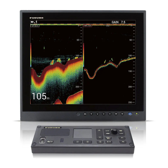
Installation Manual
FISH FINDER/ HI-RES FISH FINDER/
FISH SIZE INDICATOR
FCV-1900/B/G
Model
(Product Name: FISH FINDER)
SAFETY INSTRUCTIONS ................................................................................................ i
SYSTEM CONFIGURATION ........................................................................................... ii
EQUIPMENT LISTS........................................................................................................ iii
1. MOUNTING................................................................................................................. 1
1.1 Processor Unit ......................................................................................................................1
1.2 Control Unit ...........................................................................................................................2
1.3 Transducer............................................................................................................................3
1.4 External Monitor....................................................................................................................3
1.5 Interface Unit.........................................................................................................................3
1.6 Ethernet HUB........................................................................................................................4
1.7 Booster Box ..........................................................................................................................5
1.8 Temperature Sensor .............................................................................................................5
2. WIRING....................................................................................................................... 6
2.1 Interconnection .....................................................................................................................6
2.2 Processor Unit ......................................................................................................................7
2.3 Interface Unit.......................................................................................................................12
2.4 Net Sonde ...........................................................................................................................15
2.5 Ethernet HUB......................................................................................................................16
2.6 Booster Box ........................................................................................................................16
2.7 Input/Output Sentences ......................................................................................................17
3. INITIAL SETTINGS................................................................................................... 18
3.1 Installation Menu.................................................................................................................18
3.2 Monitor Setting....................................................................................................................19
3.3 Transducer Setting..............................................................................................................20
3.4 NMEA Port Setting..............................................................................................................23
3.5 Communication Port Monitor ..............................................................................................24
3.6 Calibration Setting...............................................................................................................25
3.7 Stabilization Setting ............................................................................................................26
3.8 Telesounder Setting............................................................................................................27
3.9 Reset to Default Setting ......................................................................................................27
3.10 Upgrading to FCV-1900B/1900G........................................................................................27
APPENDIX 1 JIS CABLE GUIDE .............................................................................AP-1
APPENDIX 2 INSTALLATION OF TEMPERATURE SENSORS .............................AP-2
PACKING LISTS ......................................................................................................... A-1
OUTLINE DRAWINGS ................................................................................................ D-1
INTERCONNECTION DIAGRAM ................................................................................ S-1
www.furuno.com
All brand and product names are trademarks, registered trademarks or service marks of their respective holders.
Advertisement
Table of Contents

Related Manuals for Furuno FCV-1900/B/G


Summary of Contents for Furuno FCV-1900/B/G
-
Page 1: Table Of Contents
Installation Manual FISH FINDER/ HI-RES FISH FINDER/ FISH SIZE INDICATOR FCV-1900/B/G Model (Product Name: FISH FINDER) SAFETY INSTRUCTIONS ....................i SYSTEM CONFIGURATION ................... ii EQUIPMENT LISTS......................iii 1. MOUNTING......................... 1 1.1 Processor Unit ........................1 1.2 Control Unit ...........................2 1.3 Transducer..........................3 1.4 External Monitor........................3... -
Page 2: Safety Instructions
The installer of the carefully, following the guidelines equipment is solely responsible for the below. proper installation of the equipment. FURUNO will assume no responsibility - Keep fuels and oils away from the for any damage associated with improper cable. installation. -
Page 3: System Configuration
SYSTEM CONFIGURATION Monitor USB connector Ethernet HUB converter (for brill-control) HUB-101 Network Fish Finder External KP DFF series, BBDS1 Processor Unit Net Sonde FCV-1901 Interface Unit NMEA0183 device FCV-1903 (Sonar, Current Indicator Satellite Compass Telesounder* FCV-1903 INTERFACE UNIT Chart Plotter, etc.) TS-80M2, TS-7100 Tankenmaru System*... -
Page 4: Equipment Lists
EQUIPMENT LISTS Standard Supply Name Type Code No. Remarks Processor unit FCV-1901 Control unit FCV-1902 Spare parts SP02-05801 001-372-670 1 set For Processor unit Installation materials CP02-09101 001-372-700 1 set For Processor unit CP03-34401 001-194-530 1 set For Control unit Optional Supply Name Type... - Page 5 EQUIPMENT LISTS Transducer (option) Output Frequency Transducer Hull Material Thru-hull pipe Tank (kHz) 1 k/ 1 k 28/50 28F-8, 50B-6/6B Steel/ FRP 28F-8, 50B-9B Steel TWB-6000 (2) T-656 28/68 28F-8, 68F-8H Steel/ FRP 28/88 28F-8, 88B-8 Steel TWB-6000 (2) T-657 50/88 50B-6/6B, 88B-8 Steel...
- Page 6 EQUIPMENT LISTS Output Frequency Transducer Hull Material Thru-hull pipe Tank (kHz) 3 k/ 3 k 38/150 38BL-15HR, 150B- Steel TFB-7000 (2) T-683 TRB-1100 (2) T-683F 38/200 38BL-15HR, 200B- Steel TFB-7000 (2) T-683 TRB-1100 (2) T-683F 50/88 50BL-24HR, 88F-126H Steel TFB-7000 (2) T-682 TRB-1100 (2) T-682F...
- Page 7 EQUIPMENT LISTS Output Frequency Transducer Hull Material Thru-hull pipe Tank (kHz) 28BL-12HR Steel TFB-5000 (1) T-616 TRB-1000 (1) T-616F 38BL-15HR Steel TFB-5000 (1) T-616 TRB-1000 (1) T-616F 50BL-24HR Steel TFB-5000 (1) T-616 TRB-1000 (1) T-616F 68F-30H Steel TFB-5000 (1) T-614 TRB-1000 (1) T-614F 88F-126H...
-
Page 8: Mounting
MOUNTING Processor Unit 1.1.1 Installation considerations The processor unit can be installed on a desktop or a bulkhead. When selecting a mounting location, keep in mind the following points: • Locate the unit out of direct sunlight. • Select an installation location that is well ventilated. •... -
Page 9: Control Unit
1. MOUNTING Control Unit 1.2.1 Installation considerations The control unit is designed to be mounted on a tabletop. When selecting a mounting location, keep in mind the following points: • Locate the unit where shock and vibration are minimal. • Leave sufficient space around the unit for maintenance and servicing. •... -
Page 10: Transducer
1. MOUNTING Transducer The performance of the fish finder depends upon the transducer position. A place least affected by air bubbles should be selected since turbulence blocks the sounding path. Further, select a place least influenced by engine noise. It is known that air bubbles are fewest at the place where the bow first falls and the next wave raises, at usual cruising speed. -
Page 11: Ethernet Hub
1. MOUNTING 1.5.1 Bulkhead mounting 1. Drill four pilot holes on the bulk- head for self-tapping screws. 2. Screw in self-tapping screws (3x20, supplied) for the upper fix- ing holes, leave 5 mm protruding. 3. Set the interface unit to the screws. -
Page 12: Booster Box
1. MOUNTING Booster Box The booster box (BT-5, option) enables connection of 5 kW transducers. For dual fre- quencies, use the model BT-5-2. 1. Unfasten four binding screws to remove the cover. 2. Select a mounting location, referring to the figure below. Fixing holes 4-φ6 terminal... -
Page 13: Wiring
WIRING Interconnection Refer to the interconnection diagram at the back of this manual for detailed informa- tion. Control unit External monitor FCV-1902 Rectifier unit RU-1746B-2 Junction box Grounding wire converter RJB-002 AC/DC power IV-1.25sq. supply unit (local supply) PR-240 Processor unit NMEA0183 FCV-1901 (Tankenmaru system*) -
Page 14: Processor Unit
2. WIRING Processor Unit LAN cable Monitor cable USB cable LAN cable Tankenmaru system Power cable Temperature Control cable sensor Transducer cable NMEA1/2 TD/ID transducer Satellite Compass cable Interface unit Net sonde signal cable Location of the connectors in the processor unit 2.2.1 Power cable and grounding Use either the DPYC-1.5 or DPYC-2.5 cable, according to the cable length. - Page 15 2. WIRING 3. Unfasten four binding screws Super Binding screws (4 pcs.) to detach the filter cover from gland the power terminal. (CN-1) 4. Unfasten and remove the seal nut from the power cable’s su- per-gland, then remove the gasket and fixture from the su- per-gland.
- Page 16 2. WIRING If the monitor has a DVI-D port, a DVI-D cable is available optionally. For the monitor unit MU-190/231/150HD, brilliance control is available, by connecting the USB cable pictured below. USB micro B (M) connector USB A (M) connector The following procedure shows how to connect the processor unit to the MU-190 mon- itor unit.
- Page 17 2. WIRING 5. Pass the A-TO-D ADAPTER cable and USB cable through the super-gland from inside. 6. Pass the gasket assembly onto the cable. 7. Insert the assembly into the seal nut, then tighten the seal nut. Super-gland Seal nut Gasket assembly 8.
- Page 18 2. WIRING 2.2.3 Transducer Lay the transducer cable well away from power cables to prevent interference. Con- nect the cable to the transducer port (for high frequency and/or low frequency) at the connector on the processor unit. Fabricate the cables as shown below. Sheath Pull the cores out from shield Braided shield...
-
Page 19: Interface Unit
2. WIRING 4. Reconnect the WAGO connector. 5. Unfasten the cable clamp screws, then pass the cables through the cable clamp. Fasten the screws to fix the cables with the cable clamp. 6. Fasten the connector cover to the chassis. For connecting the TD-ID transducer, use the WAGO connectors on CN-7. - Page 20 2. WIRING 2. Unfasten the binding screws from the case inside the interface unit. 3. Unfasten the left-hand super-gland seal nut, then remove the gasket assembly from the seal nut. To Processor unit GND terminal To Telesounder 4. Pass the UL2464-SB/1062 cable assembly end through the seal nut, fixture and gasket in order, then pass the cable through the super-gland and into the proces- sor unit.
- Page 21 2. WIRING 9. Connect the harness plug 7P to the socket J7 on the PWR board and the harness plug 16P to the socket J8. Fix the wire from connector J7 with a locking wire sad- dle in the unit. 02P6391 02P6391 Locking wire...
-
Page 22: Net Sonde
2. WIRING Net Sonde Connect the net sonde FNZ-18 or FNZ-28 to the WAGO connector CN-6 in the con- nector box in the processor unit. Connect the net sonde to the display unit with a TTYCSLA-4 cable. The following procedure shows how to connect the cables from the net sonde to the processor unit. -
Page 23: Ethernet Hub
2. WIRING Ethernet HUB Use the Ethernet HUB (HUB-101, option) to connect a network sounder, one among DFF1, DFF3 or BBDS1. No other network sounder can be connected. 1. Open the cover of the processor unit. 2. Remove super-gland CN3 and CN4. 3. -
Page 24: Input/Output Sentences
2. WIRING Input/Output Sentences This equipment can input/output the following NMEA data sentences. Data Sentence Time, position Input GNS>GGA>GLL Course over the ground (COG) and Input speed over the ground (SOG) Water speed and heading Input Water depth Output DBS, DBT, DPT Water temperature Output Target position... -
Page 25: Initial Settings
INITIAL SETTINGS This chapter provides the information necessary for initial setup of the equipment. Installation Menu 1. Press the power key to turn on the equipment. The start-up screen is displayed. After a short period of time, the installation menu is displayed. -
Page 26: Monitor Setting
3. INITIAL SETTINGS Monitor Setting Depending on your monitor, the resolution setting may need to be changed. The res- olutions available are XGA (1024x768), SXGA (1280x1024) and SXGA (1024x1280, portrait type). SXGA monitors (1280x1024) are set to the correct resolution and do not require this initial setting. -
Page 27: Transducer Setting
3. INITIAL SETTINGS Transducer Setting CAUTION Set the transducer data properly. Wrong data setting may damage the transducer and void the warranty. The menu tabs names listed below are for setting up external transducers. This allows you to adjust the transducer settings from the FCV-1900. •... - Page 28 3. INITIAL SETTINGS 6. Select [Connected] at [HF Connection]. 7. Select a frequency from the [Freq.] menu. 8. Select a transducer type from the [Transducer] menu. [Tx power] and [Voltage] are set automatically. 9. Set the LF transducer similarly. 10. If a network sounder is connected, rotate the ENTER knob to select [DFF1/DFF3/ BBDS1 Transducer].
- Page 29 3. INITIAL SETTINGS Output Frequency Model Remarks power (kW) (kHz) 28BL-12HR 38BL-15HR 50BL-24HR 68F-30H 88F-126H 100B-10R 150B-12H 200B-12H Dual frequency transducers Output Frequency (kHz) Model Remarks power (kW) 42-65/130-210 CM265LH ™ ACCU-FISH compatible 42-65/85-135 CM265LM 42-65/150-250 CM275LH-W Wide beam type 38-75/130-210 PM111LH 38-75/80-130...
-
Page 30: Nmea Port Setting
3. INITIAL SETTINGS NMEA Port Setting The [NMEA Port Set&Monitor] menu sets up the NMEA port and shows the data being input/output from the NMEA ports. Rotate the ENTER knob to select the port that you want to set up and push the knob to open the [Setting] window. -
Page 31: Communication Port Monitor
3. INITIAL SETTINGS Communication Port Monitor The communication port monitor provides information about data being input/output. 1. Press the MENU/ESC key to open the menu. 2. Confirm that the [Setting] tab is selected, then rotate the ENTER knob to select [System]. -
Page 32: Calibration Setting
3. INITIAL SETTINGS Calibration Setting The [Calib] menu mainly lets you apply offsets to speed, water temperature, and bot- tom level. For [Setting] tab For [External fish finder] tab Sound Speed 1500.0 m/s Bottom Level Temp 0.0ºF Zero Line Rejection Bottom Level Zero Line Area 4.5ft... -
Page 33: Stabilization Setting
Antenna to Transducer distances (bow-stern, port-starboard, height) are not set, Have a FURUNO technician adjust your settings. [Stabilization Area]: When heaving exceeds the value set here, stabilization is stopped and the stabilization icon at the top of the screen disappears. However, [Sta- bilization] is kept [On]. -
Page 34: Telesounder Setting
Upgrading to FCV-1900B/1900G The FCV-1900 can be upgraded to FCV-1900B or FCV-1900G with an “upgrade key”. To get the upgrade key, place an order with your local FURUNO dealer. The upgrade procedure requires a USB flash memory, USB cable (micro-B and type A connectors attached) and USB type A conversion adapter (female to female). - Page 35 3. INITIAL SETTINGS 5. Turn the processor unit on. The message shown below appeared when the system is lower than the upgrade key. Upgrade system? Note: When the upgrade key is a grade lower than the key in processor unit, the processor unit starts normally and no upgrade system message is displayed.
-
Page 36: Appendix 1 Jis Cable Guide
EX: TTYCYSLA - 4 MPYC - 4 TTYCSLA-4 # of cores Designation type Designation type # of twisted pairs The following reference table lists gives the measurements of JIS cables commonly used with Furuno products: Cable Core Core Cable Diameter Type... -
Page 37: Appendix 2 Installation Of Temperature Sensors
APPENDIX 2 INSTALLATION OF TEM- PERATURE SENSORS The installation instructions in this chapter are copied from the manufacturer’s (AIRMAR Technol- ogy Corporation) installation guide, which is included with your sensor. The model numbers mentioned within the documentation should be read as follows: T42: T-04MSB, T80: T-04MTB OWNER’S GUIDE &... -
Page 38: Installation In A Cored Fiberglass Hull
APPENDIX 2 INSTALLATION OF TEMPERATURE SENSORS 9-12 mm (3/8-1/2") pour in larger than the casting hole through the epoxy hull’s outer skin inner skin core hull thickness hull nut hull solid or hollow cylinder outer skin bedding Figure 1. Bedding and installing Figure 2. - Page 39 APPENDIX 2 INSTALLATION OF TEMPERATURE SENSORS Maintenance & Replacement Aquatic growth can accumulate rapidly on the sensor’s surface reducing its performance within weeks. Clean the surface with a ® Scotch-Brite scour pad and mild household detergent taking care to avoid making scratches. If the fouling is severe, lightly wet sand with fine grade wet/dry paper.
-
Page 40: Mounting Location
APPENDIX 2 INSTALLATION OF TEMPERATURE SENSORS OWNER’S GUIDE & INSTALLATION INSTRUCTIONS Surface Mount, Analog Record the information found on the cable tag for future reference. Part No._________________Date___________ Temperature Sensor Model T80 Follow the precautions below for optimal product performance and to reduce the risk of property damage, personal injury, and/or death. - Page 41 APPENDIX 2 INSTALLATION OF TEMPERATURE SENSORS Cable Routing & Connecting Mount the sensor near the centerline and close to the bottom of the transom. 1. Route the cable to the instrument, being careful not to tear the cable jacket when passing it through the bulkhead(s) and other Route the sensor cable over the transom, through a drain hole, or parts of the boat.
- Page 48 15/Jan/2015 H.MAKI...
- Page 52 The paper used in this manual is elemental chlorine free. ・FURUNO Authorized Distributor/Dealer 9-52 Ashihara-cho, Nishinomiya, 662-8580, JAPAN A : APR 2015 Printed in Japan All rights reserved. B : MAY 22, 2015 Pub. No. IME-23860-B (TAYA ) FCV-1900/1900B/1900G 0 0 0 1 9 0 5 0 2 1 1...