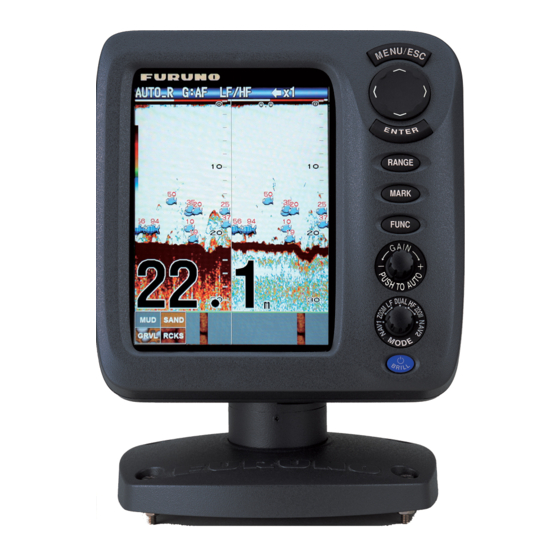
Furuno FCV-627 Operator's Manual
Fish finder
Hide thumbs
Also See for FCV-627:
- Operator's manual (83 pages) ,
- Quick manual (3 pages) ,
- Operator's manual (65 pages)
Table of Contents
Advertisement
Quick Links
Advertisement
Table of Contents
Troubleshooting

Related Manuals for Furuno FCV-627


Summary of Contents for Furuno FCV-627
- Page 2 How to discard a used battery Some FURUNO products have a battery(ies). To see if your product has a battery, see the chapter on Maintenance. Follow the instructions below if a battery is used. Tape the + and - terminals of battery before disposal to prevent fire, heat generation caused by short circuit.
- Page 3 Continued use of the equipment can Incorrect gain may give a wrong depth cause fire or electrical shock. Contact a indication, which could result in a FURUNO agent for service. dangerous situation. Do not maneuver the vessel based on The data presented by this equipment the depth indication alone.
- Page 4 Name: Warning Label (1) Do not remove the label. If the label is missing remove cover. No user-serviceable Type: 86-003-1011-3 parts inside. or damaged, contact a FURUNO agent or Code No.: 100-236-233-10 dealer about replacement. FCV-587 WARNING Name: Warning Label (2) To avoid electrical shock, do not remove cover.
-
Page 5: Table Of Contents
TABLE OF CONTENTS FOREWORD ........v 2.7 Transducer Menu......27 2.8 Demo Menu ......27 SYSTEM CONFIGURATION ....vi 2.9 Tankenmaru Menu....27 OPERATION ......... 1 MAINTENANCE, 1.1 Control Description......1 TROUBLESHOOTING....28 1.2 Power On/Off ......2 3.1 Maintenance ......28 1.3 Display Brilliance......2 3.2 How to Clean the Display Unit ..28 1.4 Display Mode ......2 3.3 Transducer Maintenance ..28 1.4.1 Single frequency display..2... -
Page 6: Foreword
LCD, 8.4 property of the LCD. inch (FCV-587) or 5.7-inch (FCV-627). The main features of the FCV-627/587 are • Bright color LCD gives excellent readability even in broad daylight. • Waterproof construction permits installa- tion on open bridge. -
Page 7: System Configuration
SYSTEM CONFIGURATION Solid lines, standard equipment; dashed lines, optional equipment, and dot-dash lines, local sup- ply. For wiring, see the interconnection diagram at the back of this manual. FCV-627 DISPLAY UNIT CV-627-E 12-24 VDC GPS Navigator External Equipment Radio Transmitter*... -
Page 8: Operation
OPERATION Control Description Control Function MENU/ESC • Opens menu. Go back one page in multi-page menu. • Escapes from current operation. • Selects items on the menu. (TrackPad) • Changes settings. • Moves VRM (Variable Range Marker) by using except for nav mode. -
Page 9: Power On/Off
1. OPERATION Power On/Off Display Mode 1. Rotate the MODE knob to open the mode 1. Press the /BRILL key to turn on the setting window, which is displayed for six power. The unit beeps then the startup seconds. screen appears. Nav data mode 1 3-5 seconds later Low frequency zoom mode*... -
Page 10: Dual Frequency Display
1. OPERATION 1.4.3 Zoom displays Picture advance Zoom mode expands chosen area of the sin- speed Gain gle frequency picture. Three modes are avail- Alarm Display able: bottom lock, bottom zoom and marker icon Range mode zoom. The default zoom mode is bottom lock. x1 x1 AUTO_R G:AF AUTO_R G:AF... -
Page 11: Nav Data Display
1. OPERATION 1.4.4 Nav data display Bottom zoom display The bottom zoom mode expands bottom and The nav data displays appear on the left 2/3 bottom fish on the left-half window. This mode of the screen. Data other than depth requires is useful for tracking bottom contour. -
Page 12: How To Select A Range
1. OPERATION How to Select a Note: The range mode indication, which ap- pears at the top-left corner, may be turned on Range or off with [Header Info] on the [Display] menu. For details, see [Header Info] on page The basic range may be selected in the [Auto] or [Manual] mode. -
Page 13: How To Measure Depth
1. OPERATION Menu Operating 2. Press the GAIN knob (or ) again to select [Fishing] or [Cruising]. Procedure [Fishing]: This mode clearly displays weaker echoes and is useful for search- Your fish finder has five main menus: Sound- ing schools of fish. "G:AF" is shown at the er, Display, Alarm, Data, and System. -
Page 14: How To Shift The Range
1. OPERATION 6. Press the ENTER key (or ) to save the 2. Select [Shift] and press the ENTER key. setting. The setting box or window disap- pears. To escape without changing a set- ting, press the MENU/ESC key instead of the ENTER key. -
Page 15: How To Reduce Interference
1. OPERATION 1.11 How to Reduce Interference Interference from other acoustic equipment operating nearby or other electronic equip- ment on your boat may show itself on the dis- play as shown in the figure below. Follow the Fast Slow procedure below to reduce interference. 1. -
Page 16: How To Reduce Low Level Noise
1. OPERATION 1.12 How to Reduce 1.13 How to Erase Low Level Noise Weak Echoes Low intensity "speckles," caused by sedi- Sediment in the water or reflections from ments in the water or noise, may appear over plankton may be painted on the display in low most of screen. -
Page 17: A-Scope Display
1. OPERATION 1.14 A-scope Display 4. Press the MENU/ESC key twice to close the window. The A-scope display shows echoes at each x1 x1 AUTO_R G:AF AUTO_R G:AF transmission with amplitudes and tone pro- portional to their intensities, on the right 1/3 of the screen. -
Page 18: Fish Information(Accu-Fish
1. OPERATION 1.15 Fish Information 1.15.1 How to activate ACCU-FISH (ACCU-FISH ACCU-FISH is inoperative when the trans- The ACCU-FISH feature measures the ducer type is selected to 600W or 1kW FCV- length of individual fish and tags the fish with 587 only), on the [Transducer] menu. -
Page 19: Fish Info
1. OPERATION 1.16 Bottom Discrimi- 4. Select desired symbol and press the EN- TER key. The size of the symbol is scaled nation Display according to the estimated length of the fish. The bottom discrimination display analyzes the bottom echo to categorize bottom hard- Striped Solid Circle Square ness in one of four types (rocks, gravel, sand,... -
Page 20: Alarms
1. OPERATION About the bottom discrimination display 5. Select [Off] or [On] and press the ENTER key to show or hide the hardness legend. • The bottom discrimination display provides To turn off the bottom discrimination display, an estimate of bottom composition. Actual select [Off] at step 3 and press the ENTER composition may be different. - Page 21 1. OPERATION The bottom alarm alerts you when the bot- 3. Select [Setting] and press the ENTER tom echo (displayed in red or reddish brown) key. If you want to change the name of an is within the alarm range set. alarm, go to step 4.
- Page 22 1. OPERATION For [ACCU-FISH] go to step 2). For other choices go to step 6). 2) Select [From] (under Starting Alarm range depth [Fish Type]) and press (width from the ENTER key. starting depth) 3) Set the minimum fish length and press the ENTER key.
- Page 23 1. OPERATION Bottom Navigation alarms 1) Set [Bottom] to [On] and press the EN- Do the following to set the navigation alarms TER key. (speed alarm and arrival alarm). 2) Select [From] and 1. Open the menu, select [Alarm] and press press the ENTER key.
-
Page 24: Func Key
1. OPERATION 1.18 FUNC Key 1.19 Waypoints The FUNC key provides for one-touch call up A waypoint can be used to mark a school of of desired function setting window. 11 items fish, reef, etc., and 20 waypoints may be en- are available: picture advance, shift, interfer- tered. - Page 25 (to the 12-24 VDC/NMEA port). Note 1: When [TLL] or [FURUNO-TLL] is selected at [TLL Output] on the [NMEA] menu of the [System] menu, the latitude and longitude position at the cursor posi- 2. Select [WPT List] and press the ENTER tion is output to the navigator.
-
Page 26: How To Edit Registered Waypoints
1. OPERATION 5. Enter name or latitude and longitude as How to erase all waypoints applicable. 1. Open the menu, select [Data] and press 6. Press the MENU/ESC key to register the the ENTER key. window. 2. Select [Delete All WPT] and press the 7. - Page 27 1. OPERATION SPEED (SOG) Two-data Three-data Four-data display display display Cross-track error Speed over the ground WIND True(or Apparent) SPEED (STW) Items displayable in (1) - (3): speed (STW)*, wind speed and direction*, destination waypoint data*, compass*, heading*, depth, position, course, range and bearing, trip meter, odometer, water temperature, air pressure, time-to-go to destination waypoint, STBD...
-
Page 28: Menu Description
1. OPERATION 1.21 Menu Description 1. Select [White Marker] in the [Sounder] menu and press the ENTER key. This section describes menu items not previ- ously mentioned. For the [System] menu, see chapter 2. Sounder menu Color Select echo color to display in white. -
Page 29: Display Menu
1. OPERATION [Bottom Zone]: Set the area where to display [S] setting, which requires speed data, selects the bottom echo when selecting the [Auto] the TX rate according to your boat’s speed. A mode on the RANGE key. high rate for fast speed; a slow rate for slow speed. - Page 30 1. OPERATION [Header Info]: Turn the operational info dis- x1 x1 AUTO_R G:AF AUTO_R G:AF play (appears at the top on the screen) on or off. Temperature Graph AUTO_R G:AF AUTO_R G:AF x1 x1 Temperature Header info Scale [Header Scale]: The header scale (below the header info) provides an estimate of time or distance.
- Page 31 1. OPERATION cations in which case they are displayed alter- [Trip Source]: Select the source for the trip nately every four seconds (default setting). indication: Select [Own] to use the speed data from the speed sensor connected to this unit, or [NMEA] to use speed data from a naviga- Data Box1 display tor.
-
Page 32: System Menu
SYSTEM MENU How to Display the Therefore, change the depth unit before changing the preset ranges. System Menu [Zoom Range]: Select the range The [System] menu mainly consists of items to zoom in the bottom zoom and which do not require regular adjustment. marker zoom modes. -
Page 33: Units Menu
2. SYSTEM MENU Units Menu [Draft]: The default depth display shows the distance from the transducer. If you would rather show the dis- tance from the sea surface, set your ship's draft. [Gain ADJ HF], [Gain ADJ LF]: If the gain is too high or too low, or the gain for the low and high frequencies appears unbalanced, you... -
Page 34: Transducer Menu
2. SYSTEM MENU Tankenmaru Menu [Zero Line Area]: This fea- ture adjusts the transmission The Tankenmaru system outputs the video line so that the transmission signal from your display unit to the display unit line disappears when the of a Tankenmaru-equipped partner ship, etc., menu item [Zero Line Rejec- via a radio transmitter. -
Page 35: Maintenance, Troubleshooting
MAINTENANCE, TROUBLE- SHOOTING How to Clean the WARNING Display Unit ELECTRICAL SHOCK HAZARD Dust or dirt may be removed from the cabinet Do not open the equipment with a soft cloth. Water-diluted mild detergent (other than when installing flush may be used if desired. DO NOT use chemi- mount hanger cover). -
Page 36: How To Replace The Fuse
3. MAINTENANCE, TROUBLESHOOTING How to Replace the Troubleshooting Fuse The table below provides basic troubleshoot- ing procedures which the user may follow to The two fuses (Type: FGBO-A 125V 2A PBF, restore normal operation. Code No.: 000-155-849-10) in the power ca- ble assy. -
Page 37: Diagnostics
Program 0252XXX-XX.XX knob’s corresponding on-screen circle "lights" in red if the knob is normal. Re- lease hold and the circle turns white. Item FCV-627 FCV-587 How to check MODE knob: Rotate the Starter 0252388-XX- 0252392-XX- knob. The corresponding on-screen circle "lights"... -
Page 38: Lcd Test
3. MAINTENANCE, TROUBLESHOOTING LCD Test How to Clear the Memory, Reset the This feature tests the LCD for proper display Odometer of colors. Note: To review the seven-tone screen easi- You can restore default menu settings and re- ly, set the brilliance to maximum before start- set the odometer (trip distance indication) as ing the test. -
Page 39: Installation
INSTALLATION Equipment List Standard supply for FCV-627 Name Type Code No. Remarks Display Unit CV-627-E With hard cover Select E: English panel CV-627-C C: Chinese panel Installation CP02-07900 1 set • Cable Assy. (Type: KON-004-02M, Materials Code No.: 000-156-405-12) • Self-tapping Screw (Type: 5×25, Code No.: 000-162-610-10, 4 pcs.) -
Page 40: Display Unit
131°F. bracket assembly. • Locate the unit away from devices that emit active gas. • The mounting location must be well venti- lated. Tape • Select a location where vibration and shock (FCV-627 only) are minimal. Bottom of the bracket... -
Page 41: Thru-Hull Mount Transducer
For planing hulls, a practical loca- tion is generally rather far astern, so that the transducer is always in water regard- less of the planing attitude. FCV-627 FCV-587 3. Set the flush mounting sponge (supplied) to the display unit. - Page 42 4. INSTALLATION smooth as possible to provide an undis- turbed flow of water around the transduc- er. The fairing block should be smaller than the transducer itself to provide a channel to divert turbulent water around the sides of the transducer rather than over its face.
-
Page 43: Transom Mount Transducer
4. INSTALLATION Transom Mount Flat Washer Transducer Rubber Washer The optional transom mount transducer is Fairing very commonly employed, usually on relative- Block ly small I/O or outboard boats. Do not use this method on an inboard motor boat because turbulence is created by the propeller ahead Hull of the transducer. -
Page 44: How To Mount A Thru-Hull Transducer Inside The Hull
4. INSTALLATION 4. Tape the location shown in the figure be- Remarks on installation low. Fill the gap between the wedge front of the transducer and transom with epoxy • Do the installation with the ship moored at a dock, etc. The water depth should be 6.5-32 material to eliminate any air spaces. -
Page 45: Triducer
4. INSTALLATION use the sandpaper to roughen the inside 9) Push the RANGE key to set the range of the hull where the transducer is to be to 10 feet (or 30 meters). mounted. 10)Press the ENTER key. 3. Wipe off any sandpaper dust from the Case 1 face of the transducer. -
Page 46: Mounting Location
4. INSTALLATION 525STID-PWD Note 1: Do not mount the sensor in an area of turbulence or bubbles: near water intake or The optional transom mount triducer discharge openings; behind strakes, struts, 525STID-PWD can be installed by the thru- fittings, or hull irregularities; behind eroding hull method or the inside-hull method. - Page 47 4. INSTALLATION 3. Using a 4 mm, #23, or 9/64" bit, drill three 19°-22° transom angle (small alumi- holes 22 mm (7/8") deep at the locations num and fiberglass boats): Position the indicated. To prevent drilling too deeply, shim with the tapered end up. wrap masking tape around the bit 22 mm 11°...
- Page 48 4. INSTALLATION Attaching the sensor to the bracket 3. On the outside of the hull secure the cable against the transom using the cable 1. If the retaining cover near the top of the clamps. Position a cable clamp 50 mm bracket is closed, open it by depressing (2") above the bracket and mark the the latch and rotating the cover down-...
-
Page 49: Speed/Temperature Sensor (Option)
4. INSTALLATION Speed/Tempera- 8. Launch the boat and check for water leak- age around the sensor. ture Sensor (option) Locknut The speed/temperature sensors (ST-02MSB Face "notch" and ST-02PSB) are designed for thru-hull toward bow. mounting. Install them as shown below. Mounting considerations Flange nut Select a suitable mounting location, consider-... -
Page 50: Wiring
4. INSTALLATION Thru-hull mount temperature sensor T-03MSB T-02MSB, T-03MSB 1. Drill a hole of 25 mm in diameter in the mounting location. Select a suitable mounting location consider- ing the following points: 2. Coat holder guide with silicone sealant, and pass gasket, washer and locknut •... - Page 51 4. INSTALLATION Fuse holder Power supply lines (red and black) Example: FCV-627 Cable tie How to ground the display unit Transducer cable Transducer CAUTION Ground (option) Switchboard, ground terminal, external equipment Be sure to ground the display unit. An improper ground or no ground can affect Cable assy.
-
Page 52: Iec 61162-1 Data Sentences
4. INSTALLATION Vinyl Sheath Connect to XDR port at rear of display unit Crimp-on Lug FV1.25-3 (LF) MJ-A10SPF Shield Taping Shrink Tubing MJ-A6SRMD MJ-A10SRMD 4.10 IEC 61162-1 Data Tape connectors with Sentences vulcanizing tape and then vinyl tape to waterproof them. The table below shows the data sentences Bind tape ends with which can be input to and output from your... -
Page 53: Adjustments After Installation
*Available with connection of applicable sen- Transducer sor or navaid. If you have the transducer 525STID-MSD or 525STID-PWD, skip this procedure. 1. Select [Type] from the [Installation] menu and press the ENTER key. FCV-587 2. Select your transducer and press the ENTER key. FCV-627... - Page 54 4. INSTALLATION Select 600W for the 600W transducer not 2. Select [NMEA] from the Installation menu listed. and press the ENTER key. Note: Do not use a 600W transducer in the 1kW setting. The transducer will be damaged. 3. Press the MENU/ESC key to finish. If you have the Tankenmaru system, go to the next section.
- Page 55 4. INSTALLATION [TLL]: Output latitude/longitude. [FURUNO-TLL]: Output latitude/longitude, depth and water temperature. Requires [FU- RUNO-TLL] enabled device. [Port Monitor]: Port Monitor shows the data sentences input to the [12-24 VDC/NMEA] port. $GPGLL, 1353. 5678, N, 11111. 1111, E, , A, D* 4B<0d><0a>...
-
Page 56: Menu Tree
APPENDIX 1 MENU TREE Bold Italic: Default Pic. Advance (x4, x2, x1, 1/2, 1/4, 1/8, 1/16, Stop) Sounder MENU key Zoom Mode (Bottom Lock, Bottom Zoom, Marker Zoom) Shift (0 - 4000 ft, 0 ft) Interference (Auto, High, Medium, Low, Off) Color Erase (0 - 50%, 0%) Clutter (0 - 100%, 0%) White Line (0 - 50%, 0%) - Page 57 Speed (kn, km/h, mph) Wind (kn, km/h, mph, m/s) Distance (NM, km, SM) NMEA NMEA0183 (Ver 1.5, Ver 2.0, Ver 3.0) NMEA Port (In/Out, In/In) NMEA Output (Off, On) WAAS Setup (Off, WAAS-00 - WAAS-27) TLL Output (Off, TLL, FURUNO-TLL) Port Monitor AP-2...
- Page 58 APPENDIX 1 MENU TREE Calib Draft (-15.0 - +50.0 ft, +0.0 ft) Gain ADJ HF (-20 - +20, +0) Gain ADJ LF (-20 - +20, +0) Temp (-20.0 - +20.0 °F, +0.0 °F) Speed(STW) (-50 - +50 %, +0 %) Fish Size (-80 - +100, +0 %) Water Type (Salt, Fresh) Zero Line...
-
Page 59: Specifications
FURUNO FCV-627/587 SPECIFICATIONS OF FISH FINDER FCV-627/587 GENERAL TX frequency 50 kHz and 200 kHz Transmit method Single or dual frequency transmitting Output power FCV-627 600 W FCV-587 600/1000 W TX rate Max. 3,000 pulse/min Pulse length 0.04 to 3.0 ms Sensitivity 10 dBμV... - Page 60 FURUNO FCV-627/587 INTERFACE Data format IEC61162-1 (NMEA0183 Ver 1.5/2.0/3.0) Data sentences Input BWC, GGA, GLL, GNS, HDG, HDT, MDA, MTW, MWV, RMA, RMB, RMC, VHW, VTG, XTE, ZDA Output DBS, DBT, DPT, MTW*, RMB*, VHW*, TLL* by key operation *: External data required...
-
Page 68: Index
INDEX LCD test ............31 LF display............2 ACCU-FISH alarm........14 ACCU-FISH setup........11 Arrival alarm ..........16 Maintenance..........28 A-scope display...........10 Marker zoom display ........4 MODE knob...........2 Battery............23 Battery voltage alert ........29 Nav data display........4 Bearing source ..........24 Bottom discrimination display......12 Palette ............23 Bottom fish alarm ........14 Picture advance speed........7 Bottom lock display ........3 Bottom type alarm ........15... - Page 69 When a claim is made, FURUNO has a right to choose whether with other electronic devices. The imported product may also be to repair the product or replace it.
- Page 70 24 months from installation date provided the work is done by Furuno U.S.A., Inc. or an AUTHORIZED Furuno dealer during normal shop hours and within a radius of 50 miles of the shop location.