Table of Contents
Advertisement
Advertisement
Table of Contents
Troubleshooting

Related Manuals for Furuno FCV-288


Summary of Contents for Furuno FCV-288
- Page 2 ・FURUNO Authorized Distributor/Dealer 9-52 Ashihara-cho, Nishinomiya, 662-8580, JAPAN A : APR 2012 Printed in Japan All rights reserved. D : AUG . 08, 2014 Pub. No. OME-23830-D ( GREG ) FCV-288 0 0 0 1 7 6 5 7 9 1 3...
- Page 3 How to discard a used battery Some FURUNO products have a battery(ies). To see if your product has a battery, see the chapter on Maintenance. Follow the instructions below if a battery is used. Tape the + and - terminals of battery before disposal to prevent fire, heat generation caused by short circuit.
- Page 4 Continued use of the equipment can Adjust the gain correctly. cause fire or electrical shock. Contact a FURUNO agent for service. Incorrect gain may give a wrong depth indication, which could result in a Do not maneuver the vessel based on dangerous situation.
- Page 5 To avoid electrical shock, do not Type: 02-166-1123-0 remove cover. No user-serviceable the labels are missing or damaged, contact a parts inside. FURUNO agent or dealer about replacement. Name: Danger Label HV Type: 02-166-1124-1 Name: Danger Label Type: 02-166-1126-1 Safety Instructions for the Installer...
-
Page 6: Table Of Contents
TABLE OF CONTENTS FOREWORD ........v 3.7 Diagnostics .......23 3.8 LCD Test........24 SYSTEM CONFIGURATION ....vi 3.9 How to Clear the Memory, Reset the Odometer....24 OPERATION ......... 1 1.1 Control Description......1 INSTALLATION ......25 1.2 Power On/Off ......2 4.1 Equipment Lists ......25 1.3 Display Brilliance......2 4.2 Display Unit.......27 1.4 Display Mode ......2... -
Page 7: Foreword
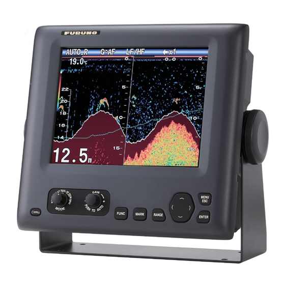
Thank you for considering and purchasing FURUNO equipment. Features The FURUNO FCV-288 is a dual frequency (50 kHz and 200 kHz) Fish Finder. Comprised of a display unit and a transducer, the FCV-288 displays underwater conditions on a 10.4-inch color LCD in various colors according to echo strength. -
Page 8: System Configuration
SYSTEM CONFIGURATION Standard configuration is shown below with solid line. DISPLAY UNIT CV-288 Navigation Power Equipment 12-24 VDC Rectifier PR-62 100/110/115/ 220/230 VAC 1φ, 50/60 Hz Water Temperature Sensor T42, T80 Water Temp.+Speed Sensor ST-02MSB, ST-02PSB High Freq. Freq. Transducer Transducer... -
Page 9: Operation
OPERATION Control Description Control Function Short press: Turns on power; opens the [Brill] adjustment window. BRILL Long press: Turns off power. MODE Selects display mode. GAIN Push: Opens [Auto Gain] setting window. Rotate: Manually adjusts gain. FUNC Short press: Opens window programmed. Long press: Opens function key programming window. -
Page 10: Power On/Off
1. OPERATION Power On/Off Display Mode 1. Rotate the MODE knob to open the mode 1. Press the BRILL key to turn on the setting window, which is displayed for six power. The unit beeps then the startup seconds. screen appears. Nav data mode 1 Low frequency zoom mode* Low frequency mode (50 kHz) -
Page 11: Dual Frequency Display
1. OPERATION left half of the screen. This mode is useful for Picture advance detecting bottom fish. Gain speed Display mode Bottom lock display Single freq. display Range Alarm icon AUTO_R LF L:AF AUTO_R BL-LF L:AF 11.1 kt SOG Zero line °C Data box Depth scale... -
Page 12: Nav Data Display
1. OPERATION 1.4.4 Nav data display Marker zoom display The marker zoom mode expands the chosen The nav data displays appear on the left 2/5 area of the normal picture to full vertical size of the screen. Data other than depth requires of the screen on the left-half window. -
Page 13: How To Select A Range
1. OPERATION How to Select a How to Adjust the Range Gain The basic range may be selected in the [Auto] How to select the gain adjustment mode or [Manual] mode. The gain may be adjusted automatically 1. Press the RANGE key to open the ([Fishing] or [Cruising]) or manually. -
Page 14: How To Measure Depth
1. OPERATION How to Measure [Cruising]: This mode clearly displays stronger echoes (for example, bottom) Depth and suppresses weak echoes. Use this mode for general cruising. "G:AC" is The VRM (Variable Range Marker) functions shown at the top left corner on the screen. to measure the depth to schools of fish, etc. -
Page 15: How To Shift The Range
1. OPERATION 2. Use to select the main menu de- sired. The cursor (yellow) highlights cur- rent selection. The items in the sub menu change with the menu selected. “Window” can be 3. Press the ENTER key (or ). The cursor shifted up and (yellow) shifts to the sub menu and the down to select... -
Page 16: Picture Advance Speed
1. OPERATION 1.10 Picture Advance picture advance speed is displayed at the top-right corner of the screen. Speed CAUTION The picture advance speed determines how quickly the vertical scan lines run across the The picture is not refreshed when screen. When selecting a picture advance picture advancement is stopped. -
Page 17: How To Reduce Low Level Noise
1. OPERATION 3. Select the degree of interference reduc- 3. Select the degree of clutter reduction de- tion desired and press the ENTER key. sired and press the ENTER key. The set- [Auto]: Interference is suppressed auto- ting range is 0% to 100% in intervals of matically. -
Page 18: A-Scope Display
1. OPERATION 3. Select the color to erase and press the 4. Press the MENU ESC key twice to close ENTER key. The setting range is 0 to the window. 50% in intervals of one per cent. The larg- AUTO_R L:AF er the setting value, the greater the num- ber of colors that are erased. - Page 19 1. OPERATION How to activate a fish alarm 4. To change the name of the alarm, select [Name] and Multiple fish alarms (ALARM1 - ALARM3, de- press the ENTER key. fault names) can be activated. In this case, 5. Enter the name of the alarm. the audio and visual alarms are released (Max.
- Page 20 1. OPERATION 4) Select the [From] that is below [Depth] 2) Select [From] and and press the ENTER key. press the ENTER key. 3) Enter the starting tem- perature for the alarm and press the ENTER key. 4) Select [Span] and press the ENTER key.
-
Page 21: Func Key
1. OPERATION 1.16 FUNC Key 1.17 Position Data The FUNC key provides for one-touch call up To output the position data, follow the proce- of desired function setting window. 8 items dure below. are available: picture advance, shift, interfer- 1. Press the MARK key. The cross cursor ence, clutter, color erase, white line, white appears on the screen. -
Page 22: Setting Up Nav Data Displays
1. OPERATION 1.18 Setting Up Nav Note: When a data is lost 30 sec., the display shows "- -" at the lost data’s location. Data Displays The user may arrange the nav data displays as desired. 1.18.1 Nav data displays 1. -
Page 23: Menu Description
1. OPERATION 1.19 Menu Description [White Marker]: Display the selected echo color in white. This section describes menu items not previ- 1. Select [White Marker] in the [Sounder] ously mentioned. For the [System] menu, see menu and press the ENTER key. chapter 2. - Page 24 1. OPERATION [TX Power]: Interference may appear on the screen when an echo sounder having the AUTO_R L:AF same frequency as your own is being operat- ed in the vicinity of your vessel. In this case, lower your TX power and contact the vessel to Water temp scale request them to reduce their TX power.
- Page 25 1. OPERATION Data menu 4. Select a data and press the ENTER key. 5. Select [On] or [Off] and press the ENTER This menu mainly sets up how to display data key. input by external equipment. 6. Repeat steps 4 and 5 to show or hide oth- er items.
-
Page 26: System Menu
SYSTEM MENU How to Display the Range Menu System Menu The [System] menu mainly consists of items which do not require regular adjustment. 1. Press the MENU ESC key to open the menu. 2. Select [System]. For [Tests], and [Re- store], see chapter 3. -
Page 27: Key Menu
2. SYSTEM MENU Key Menu Calib Menu [FUNC Key]: Select the item to program to the FUNC key. The programming can also be done by long-pressing the FUNC key. See paragraph 1.16.2. [Key Beep]: Turn key beep on or off. Language Menu [Draft]: The default depth display shows the distance... -
Page 28: Demo Menu
2. SYSTEM MENU [Zero Line Rejector]: Turn the zero line (transmission line) on or off. When turned on, the transmission line disappears, which al- lows you to see fish echoes near the surface clearly. The length of the transmission line changes with transducer used and installation characteristics. -
Page 29: Maintenance, Troubleshooting
MAINTENANCE, TROUBLESHOOTING How to Clean the WARNING Display Unit ELECTRICAL SHOCK HAZARD Dust or dirt may be removed from the cabinet Do not open the equipment. with a soft cloth. Water-diluted mild detergent may be used if desired. DO NOT use chemi- Only qualified personnel can work cal cleaners to clean the display unit;... -
Page 30: How To Replace The Fuse
3. MAINTENANCE, TROUBLESHOOTING How to Replace the Troubleshooting Fuse The table below provides basic troubleshoot- ing procedures which the user may follow to If you cannot turn on the power, the fuse restore normal operation. (Type: FGBO-A 125V 3A PBF, Code No.: 000-155-850-10) may have blown. -
Page 31: Diagnostics
3. MAINTENANCE, TROUBLESHOOTING Diagnostics 3. The ovals and circles at the bottom of the test display are for checking the controls. If you feel your unit is not working properly, How to check key and TrackPad: Press conduct the diagnostic test to find the prob- each key and the arrows on the TrackPad lem. -
Page 32: Lcd Test
3. MAINTENANCE, TROUBLESHOOTING LCD Test How to Clear the Memory, Reset the This feature tests the LCD for proper display Odometer of colors. Note: To review the seven-tone screen easi- You can restore default menu settings and re- ly, set the brilliance to maximum before start- set the odometer (trip distance indication) as ing the test. -
Page 33: Installation
INSTALLATION Equipment Lists Standard supply Name Type Code No. Remarks Display Unit CV-288 – Installation Materials 1 set See packing list at back of this man- ual. Spare Parts 1 set Option Name Type Code No. Remarks Transducer See next page –... - Page 34 4. INSTALLATION Combination of transducer, thru-hull pipe and tank Output Frequency Ship type Transducer Thru-hull pipe Tank (kHz) 1k/1k 50/200 Steel 50/200-1T TFB-5000(1) T-603 – T-603F 1k/2k 50/200 Steel 50B-9B TWB-6000(2) T-658 200B-8/8B 2k/2k 50/200 Steel 50BL-12HR TFB-7000(2) T-693 200B-8/8B TRB-1100(2) T-693-F 3k/3k...
-
Page 35: Display Unit
4. INSTALLATION Display Unit Preparation for installation 1. Open the back cover.The power cable and water temperature/speed sensor ca- NOTICE ble are tied to a plate with cable ties.Cut the cable tie which binds the power cable. Do not apply paint, anti-corrosive sealant or contact spray to coating or plastic (Rear view) parts of the equipment. -
Page 36: Transducer
4. INSTALLATION Transducer The performance of the echo sounder depends upon the transducer position. A place least affect- ed by air bubbles should be selected since turbulence blocks the sounding path. Further, select a place least influenced by engine noise. It is known that air bubbles are fewest at the place where the bow first falls and the next wave rises, at usual cruising speed. -
Page 37: Wiring
100/110/115/ Water temp. 12-24 VDC 220/230 VAC High sensor (Connect to a 1ø, 50/60 Hz dedicated Grounding wire: Transducer breaker in the Transducer As short as possible mains 200 kHz only. 50 kHz only. switchboard.) Wiring diagram for FCV-288... -
Page 38: Cable Fabrication
4. INSTALLATION Cable Fabrication Power cable Connect the power cable to the power connector. Connect the leads to the battery (12 or 24 VDC); white to plus(+) terminal and black to minus(-) terminal. Connect the shield to ship’s ground. Cable connector Power cable Lead wire Black... - Page 39 4. INSTALLATION WAGO connector (for transducer and NMEA ports) Press 1. Twist conductors. 2. Insert opener and press Opener it down. (Large one: for transducer port 3. Insert core to hole. Small one: for NMEA port) 4. Release opener. 5. Pull the core to confirm Twist.
-
Page 40: Transducer Setting
LO-RAN-C data. Latitude, longitude, Transducer type and tap setting TD, ground speed and course The following table shows the transducers Recommended programmed in the FCV-288. mini-mum specific GPS/TRANSIT da- Output Type ta. Lati-tude and (kW) longitude, speed 50B-6... -
Page 41: Adjustments After Installation
4. INSTALLATION Adjustments after Output sentences Installation Sentence Data Remarks Depth below Language sea surface Depth below transducer 1. Press the BRILL key to show the [In- Depth below stallation] menu. transducer and offset MTW* Water Output only tempera-ture when [Temp Source] of [Data] menu is set to... -
Page 42: Nmea Port Setting
TLL Output: Output the position selected by the MARK key to the plotter connected. • [Off]: Does not output latitude/longitude. • [TLL]: Outputs latitude/longitude. • [FURUNO-TLL]: Outputs latitude/longitude, depth and water temperature. This requires FURUNO-TLL enabled device. Port Monitor: Port Monitor provides informa- tion for the data sentences input to the NMEA port. -
Page 43: Menu Tree
APPENDIX 1 MENU TREE Bold Italic: Default Pic. Advance (x4, x2, x1, 1/2, 1/4, 1/8, 1/16, Stop) Sounder MENU key Zoom Mode (Bottom Lock, Bottom Zoom, Marker Zoom) Shift (0 - 6000 ft, 0 ft) Interference (Auto, High, Medium, Low, Off) Color Erase (0 - 50%, 0%) Clutter (0 - 100%, 0%) White Line (0 - 100%, Edge, 0%) - Page 44 Units Depth (m, ft, fm) Temp (°C, °F) NMEA NMEA0183 (Ver 1.5, Ver 2.0, Ver 3.0) TLL Output (Off, TLL, FURUNO-TLL) Port Monitor Calib Draft (-15.0 - +50.0 ft, +0.0 ft) Gain ADJ HF (-20 - +20, +0) Gain ADJ LF (-20 - +20, +0) Temp (-20.0 - +20.0 °F, +0.0 °F)
-
Page 45: Sensors
APPENDIX 2 T42 AND T80 TEMPERATURE SENSORS The following pages of this appendix provide a copy of the installation instructions for AIRMAR temperature sensors T42 and T80. AP-3... - Page 46 OWNER’S GUIDE & INSTALLATION INSTRUCTIONS Thru-Hull, Analog Record the information found on the cable tag for future reference. Part No._________________Date___________ High-Precision Temperature Sensor Model T42 Follow the precautions below for optimal product performance and to reduce the risk of property damage, personal injury, and/or death. WARNING: Always wear safety goggles and a dust mask when installing.
-
Page 47: Installation In A Cored Fiberglass Hull
9-12 mm (3/8-1/2") pour in larger than the casting hole through the epoxy hull’s outer skin inner skin core hull thickness hull nut hull solid or hollow cylinder outer skin bedding Figure 1. Bedding and installing Figure 2. Preparing a cored fiberglass hull Copyright ©... - Page 48 Maintenance & Replacement Aquatic growth can accumulate rapidly on the sensor’s surface reducing its performance within weeks. Clean the surface with a Scotch-Brite® scour pad and mild household detergent taking care to avoid making scratches. If the fouling is severe, lightly wet sand with fine grade wet/dry paper.
- Page 49 35 Meadowbrook Drive, Milford, New Hampshire 03055-4613, USA • www.airmar.com Copyright © 2014 Airmar Technology Corp. All rights reserved. AP-7...
-
Page 50: Temperature Sensor
OWNER’S GUIDE & INSTALLATION INSTRUCTIONS Surface Mount, Analog Record the information found on the cable tag for future reference. Part No._________________Date___________ Temperature Sensor Model T80 Follow the precautions below for optimal product performance and to reduce the risk of property damage, personal injury, and/or death. Tools &... - Page 51 Mount the sensor near the centerline and close to the bottom of Cable Routing & Connecting the transom. 1. Route the cable to the instrument, being careful not to tear the cable jacket when passing it through the bulkhead(s) and other Route the sensor cable over the transom, through a drain hole, or parts of the boat.
-
Page 52: Specifications
FURUNO FCV-288 SPECIFICATIONS OF COLOR LCD FISH FINDER FCV-288 GENERAL TX frequency 50 kHz and 200 kHz, dual frequency transmission Output power 1, 2 or 3 kW selectable Power reduction Auto, 10 to 100% (10% step) TX rate Max. 3000 pulse/min Pulse length Max. -
Page 56: Index
INDEX A-scope display...........10 Nav data display........4 Battery............16 Palette ............16 Battery voltage alert ........22 Picture advance speed........8 Bearing source ..........17 Bottom............11 Range............5 Bottom fish alarm ........11 RANGE key...........5 Bottom lock display ........3 Range menu..........18 Bottom zoom display........3 Range shift ............7 BRILL key............2 Brilliance............2 Shifting range ..........7...