ZyXEL Communications ZyWall USG20-VPN User Manual
Usg series
Hide thumbs
Also See for ZyWall USG20-VPN:
- User manual (994 pages) ,
- Handbook (810 pages) ,
- Reference manual (665 pages)
Table of Contents
Advertisement
Advertisement
Table of Contents
Troubleshooting

Related Manuals for ZyXEL Communications ZyWall USG20-VPN


Summary of Contents for ZyXEL Communications ZyWall USG20-VPN
- Page 1 ZyWALL/USG Series USG20-VPN / USG20W-VPN VPN Firewalls Version 4.16 Edition 1, 1/2016 Quick Start Guide User’s Guide Default Login Details LAN Port IP Address https://192.168.1.1 User Name admin www.zyxel.com Password 1234 Copyright © 2016 ZyXEL Communications Corporation...
- Page 2 IMPORTANT! READ CAREFULLY BEFORE USE. KEEP THIS GUIDE FOR FUTURE REFERENCE. This is a User’s Guide for a series of products. Not all products support all firmware features. Screenshots and graphics in this book may differ slightly from your product due to differences in your product firmware or your computer operating system.
-
Page 3: Table Of Contents
Part I: User’s Guide ..................17 Chapter 1 Introduction............................19 1.1 Overview ............................19 1.1.1 Applications ..........................19 1.2 Management Overview ........................21 1.3 Web Configurator ..........................23 1.3.1 Web Configurator Access ......................23 1.3.2 Web Configurator Screens Overview ..................25 1.3.3 Navigation Panel ........................29 1.3.4 Tables and Lists ........................34 Chapter 2 Installation Setup Wizard ........................37 2.1 Installation Setup Wizard Screens ....................37... - Page 4 4.3 VPN Setup Wizard ..........................56 4.3.1 Welcome ..........................57 4.3.2 VPN Setup Wizard: Wizard Type .....................58 4.3.3 VPN Express Wizard - Scenario .....................58 4.3.4 VPN Express Wizard - Configuration ..................60 4.3.5 VPN Express Wizard - Summary ...................60 4.3.6 VPN Express Wizard - Finish ....................61 4.3.7 VPN Advanced Wizard - Scenario ..................62 4.3.8 VPN Advanced Wizard - Phase 1 Settings ................63 4.3.9 VPN Advanced Wizard - Phase 2 ...................65...
- Page 5 5.2.11 Interface Status Summary Screen ..................94 5.2.12 Secured Service Status Screen .....................95 5.2.13 Content Filter Statistics Screen .....................96 5.2.14 Top 5 IPv4/IPv6 Security Policy Rules that Blocked Traffic Screen ........97 5.2.15 The Latest Alert Logs Screen ....................97 Part II: Technical Reference................99 Chapter 6 Monitor...............................101 6.1 Overview ............................101...
- Page 6 Chapter 7 Licensing ............................134 7.1 Registration Overview ........................134 7.1.1 What you Need to Know ......................134 7.1.2 Registration Screen .......................135 7.1.3 Service Screen ........................135 Chapter 8 Wireless .............................137 8.1 Overview ............................137 8.1.1 What You Can Do in this Chapter ..................137 8.1.2 What You Need to Know ......................137 8.2 AP Management Screen ........................138 8.3 DCS Screen ...........................139 8.4 Technical Reference ........................139...
- Page 7 9.8.2 Bridge Add/Edit ........................205 9.9 Virtual Interfaces ..........................214 9.9.1 Virtual Interfaces Add/Edit .....................214 9.10 Interface Technical Reference .......................216 9.11 Trunk Overview ..........................219 9.11.1 What You Need to Know ......................219 9.12 The Trunk Summary Screen ......................222 9.12.1 Configuring a User-Defined Trunk ..................223 9.12.2 Configuring the System Default Trunk ................225 Chapter 10 Routing ..............................227...
- Page 8 12.2.1 The NAT Add/Edit Screen ....................258 12.3 NAT Technical Reference ......................261 Chapter 13 HTTP Redirect ...........................263 13.1 Overview ............................263 13.1.1 What You Can Do in this Chapter ..................263 13.1.2 What You Need to Know ......................263 13.2 The HTTP Redirect Screen ......................264 13.2.1 The HTTP Redirect Edit Screen ..................265 Chapter 14 ALG ..............................267...
- Page 9 17.1 Overview ............................288 17.1.1 What You Can Do in this Chapter ..................288 17.2 Layer-2 Isolation General Screen ....................289 17.3 White List Screen ..........................289 17.3.1 Add/Edit White List Rule .....................290 Chapter 18 Inbound Load Balancing........................292 18.1 Inbound Load Balancing Overview ....................292 18.1.1 What You Can Do in this Chapter ..................292 18.2 The Inbound LB Screen ........................293 18.2.1 The Inbound LB Add/Edit Screen ..................294...
- Page 10 20.5.1 The Session Control Add/Edit Screen .................329 20.6 Security Policy Example Applications ...................330 Chapter 21 IPSec VPN............................333 21.1 Virtual Private Networks (VPN) Overview ..................333 21.1.1 What You Can Do in this Chapter ..................335 21.1.2 What You Need to Know ......................336 21.1.3 Before You Begin .........................337 21.2 The VPN Connection Screen ......................338 21.2.1 The VPN Connection Add/Edit (IKE) Screen ...............339...
- Page 11 23.7.2 Opening a File or Folder ......................387 23.7.3 Downloading a File ......................388 23.7.4 Saving a File ........................388 23.7.5 Creating a New Folder ......................389 23.7.6 Renaming a File or Folder ....................389 23.7.7 Deleting a File or Folder ......................390 23.7.8 Uploading a File ........................390 Chapter 24 USG SecuExtender (Windows) ......................392 24.1 The USG SecuExtender Icon ......................392...
- Page 12 27.4 Content Filter Trusted Web Sites Screen ..................431 27.5 Content Filter Forbidden Web Sites Screen .................432 27.6 Content Filter Technical Reference ....................433 Chapter 28 Anti-Spam ............................435 28.1 Overview ............................435 28.1.1 What You Can Do in this Chapter ..................435 28.1.2 What You Need to Know ......................435 28.2 Before You Begin ..........................436 28.3 The Anti-Spam Profile Screen .......................437 28.3.1 The Anti-Spam Profile Add or Edit Screen ................438...
- Page 13 29.6.2 The Service Summary Screen .....................493 29.6.3 The Service Group Summary Screen .................495 29.7 Schedule Overview ........................497 29.7.1 What You Need to Know ......................497 29.7.2 The Schedule Summary Screen ..................498 29.7.3 The Schedule Group Screen ....................501 29.8 AAA Server Overview .........................502 29.8.1 Directory Service (AD/LDAP) ....................503 29.8.2 RADIUS Server ........................503 29.8.3 ASAS ...........................503...
- Page 14 30.6.4 PTR Record .........................549 30.6.5 Adding an Address/PTR Record ..................549 30.6.6 CNAME Record ........................549 30.6.7 Adding a CNAME Record ....................550 30.6.8 Domain Zone Forwarder .....................550 30.6.9 Adding a Domain Zone Forwarder ..................550 30.6.10 MX Record ........................551 30.6.11 Adding a MX Record ......................552 30.6.12 Security Option Control .....................552 30.6.13 Editing a Security Option Control ..................552 30.6.14 Adding a DNS Service Control Rule ..................553...
- Page 15 31.1 Overview ............................590 31.1.1 What You Can Do In this Chapter ..................590 31.2 Email Daily Report ........................590 31.3 Log Setting Screens ........................592 31.3.1 Log Settings .........................593 31.3.2 Edit System Log Settings ....................594 31.3.3 Edit Log on USB Storage Setting ..................597 31.3.4 Edit Remote Server Log Settings ..................599 31.3.5 Log Category Settings Screen .....................601 Chapter 32...
- Page 16 35.1 Overview ............................636 35.1.1 What You Need To Know .....................636 35.2 The Shutdown Screen ........................636 Chapter 36 Troubleshooting..........................637 36.1 Resetting the USG ........................645 36.2 Getting More Troubleshooting Help ....................646 Appendix A Customer Support ......................647 Appendix B Legal Information......................653 Appendix C Product Features......................662 Index ..............................666 USG20(W)-VPN Series User’s Guide...
-
Page 17: Part I User's Guide
User’s Guide... -
Page 19: Chapter 1 Introduction
H A PT ER Introduction 1.1 Overview “USG” in this User’s Guide refers to all USG models in the series. Table 1 USG Models USG20-VPN USG20W-VPN USG20W-VPN has built-in Wi-Fi functionality • See Table 12 on page 48 for default port / interface name mapping. See Table 13 on page 49 default interface / zone mapping. - Page 20 Chapter 1 Introduction IPv6 Routing The USG supports IPv6 Ethernet, PPP, VLAN, and bridge routing. You may also create IPv6 policy routes and IPv6 objects. The USG can also route IPv6 packets through IPv4 networks using different tunneling methods. Figure 2 Applications: IPv6 Routing VPN Connectivity Set up VPN tunnels with other companies, branch offices, telecommuters, and business travelers to provide secure access to your network.
-
Page 21: Management Overview
Chapter 1 Introduction Figure 4 SSL VPN With Full Tunnel Mode LAN (192.168.1.X) Web Mail File Share Non-Web https:// Application Server Web-based Application User-Aware Access Control Set up security policies to restrict access to sensitive information and shared resources based on the user who is trying to access it. - Page 22 Chapter 1 Introduction Web Configurator The Web Configurator allows easy USG setup and management using an Internet browser. This User’s Guide provides information about the Web Configurator. Figure 7 Managing the USG: Web Configurator Command-Line Interface (CLI) The CLI allows you to use text-based commands to configure the USG. Access it using remote management (for example, SSH or Telnet) or via the physical or Web Configurator console port.
-
Page 23: Web Configurator
Chapter 1 Introduction Cloud CNM Use the CloudCNM screen (see Section 30.13 on page 583) to enable and configure management of the USG by a Central Network Management system. 1.3 Web Configurator In order to use the Web Configurator, you must: •... - Page 24 Chapter 1 Introduction The Network Risk Warning screen displays any unregistered or disabled security services. Select how often to display the screen and click OK. If you select Never and you later want to bring this screen back, use these commands (note the space before the underscore).
-
Page 25: Web Configurator Screens Overview
Chapter 1 Introduction Follow the directions in the Update Admin Info screen. If you change the default password, the Login screen appears after you click Apply. If you click Ignore, the Installation Setup Wizard opens if the USG is using its default configuration; otherwise the dashboard appears. 1.3.2 Web Configurator Screens Overview The Web Configurator screen is divided into these parts (as illustrated on page... - Page 26 Chapter 1 Introduction The title bar icons in the upper right corner provide the following functions. Table 3 Title Bar: Web Configurator Icons LABEL DESCRIPTION Logout Click this to log out of the Web Configurator. Help Click this to open the help page for the current screen. About Click this to display basic information about the USG.
- Page 27 Chapter 1 Introduction Figure 10 Site Map Object Reference Click Object Reference to open the Object Reference screen. Select the type of object and the individual object and click Refresh to show which configuration settings reference the object. Figure 11 Object Reference The fields vary with the type of object.
- Page 28 Chapter 1 Introduction Table 5 Object References (continued) LABEL DESCRIPTION Priority If it is applicable, this field lists the referencing configuration item’s position in its list, otherwise N/A displays. Name This field identifies the configuration item that references the object. Description If the referencing configuration item has a description configured, it displays here.
-
Page 29: Navigation Panel
Chapter 1 Introduction Figure 13 CLI Messages 1.3.3 Navigation Panel Use the navigation panel menu items to open status and configuration screens. Click the arrow in the middle of the right edge of the navigation panel to hide the panel or drag to resize it. The following sections introduce the USG’s navigation panel menus and their screens. -
Page 30: Monitor Menu
Chapter 1 Introduction Monitor Menu The monitor menu screens display status and statistics information. Table 6 Monitor Menu Screens Summary FOLDER OR LINK TAB FUNCTION System Status Port Statistics Port Displays packet statistics for each physical port. Statistics Interface Interface Displays general interface information and packet statistics. -
Page 31: Configuration Menu
Chapter 1 Introduction Configuration Menu Use the configuration menu screens to configure the USG’s features. Table 7 Configuration Menu Screens Summary FOLDER OR LINK TAB FUNCTION Quick Setup Quickly configure WAN interfaces or VPN connections. Licensing Registration Registration Register the device and activate trial services. Service View the licensed service status and upgrade licensed services. - Page 32 Chapter 1 Introduction Table 7 Configuration Menu Screens Summary (continued) FOLDER OR LINK TAB FUNCTION Policy Control Policy Create and manage level-3 traffic rules and apply UTM profiles. Session Session Control Limit the number of concurrent client NAT/security policy sessions. Control IPSec VPN VPN Connection...
- Page 33 Chapter 1 Introduction Table 7 Configuration Menu Screens Summary (continued) FOLDER OR LINK TAB FUNCTION Service Service Create and manage TCP and UDP services. Service Group Create and manage groups of services to apply to policies as a single object. Schedule Schedule Create one-time and recurring schedules.
-
Page 34: Tables And Lists
Chapter 1 Introduction Maintenance Menu Use the maintenance menu screens to manage configuration and firmware files, run diagnostics, and reboot or shut down the USG. Table 8 Maintenance Menu Screens Summary FOLDER FUNCTION OR LINK File Configuration File Manage and upload configuration files for the USG. Manager Firmware Package View the current firmware version and upload firmware. - Page 35 Chapter 1 Introduction Figure 16 Common Table Column Options Select a column heading cell’s right border and drag to re-size the column. Figure 17 Resizing a Table Column Select a column heading and drag and drop it to change the column order. A green check mark displays next to the column’s title when you drag the column to a valid new location.
- Page 36 Chapter 1 Introduction Figure 20 Common Table Icons Here are descriptions for the most common table icons. Table 9 Common Table Icons LABEL DESCRIPTION Click this to create a new entry. For features where the entry’s position in the numbered list is important (features where the USG applies the table’s entries in order like the security policy for example), you can select an entry and click Add to create a new entry after the selected entry.
-
Page 37: Installation Setup Wizard
H A PT ER Installation Setup Wizard 2.1 Installation Setup Wizard Screens When you log into the Web Configurator for the first time or when you reset the USG to its default configuration, the Installation Setup Wizard screen displays. This wizard helps you configure Internet connection settings and activate subscription services. -
Page 38: Internet Access: Ethernet
Chapter 2 Installation Setup Wizard Figure 23 Internet Access: Step 1 • I have two ISPs: Select this option to configure two Internet connections. Leave it cleared to configure just one. This option appears when you are configuring the first WAN interface. •... -
Page 39: Internet Access: Pppoe
Chapter 2 Installation Setup Wizard Figure 24 Internet Access: Ethernet Encapsulation • Encapsulation: This displays the type of Internet connection you are configuring. • First WAN Interface: This is the number of the interface that will connect with your ISP. •... - Page 40 Chapter 2 Installation Setup Wizard Figure 25 Internet Access: PPPoE Encapsulation 2.1.3.1 ISP Parameters • Type the PPPoE Service Name from your service provider. PPPoE uses a service name to identify and reach the PPPoE server. You can use alphanumeric and -_@$./ characters, and it can be up to 64 characters long.
-
Page 41: Internet Access: Pptp
Chapter 2 Installation Setup Wizard • First / Second DNS Server: These fields display if you selected static IP address assignment. The Domain Name System (DNS) maps a domain name to an IP address and vice versa. Enter a DNS server's IP address(es). The DNS server is extremely important because without it, you must know the IP address of a computer before you can access it. -
Page 42: Internet Access Setup - Second Wan Interface
Chapter 2 Installation Setup Wizard 2.1.4.2 PPTP Configuration • Base Interface: This identifies the Ethernet interface you configure to connect with a modem or router. • Type a Base IP Address (static) assigned to you by your ISP. • Type the IP Subnet Mask assigned to you by your ISP (if given). •... -
Page 43: Internet Access Succeed
Chapter 2 Installation Setup Wizard 2.1.6 Internet Access Succeed This screen shows your Internet access settings that have been applied successfully. Figure 28 Internet Access Succeed 2.1.7 Wireless Settings: SSID & Security Configure SSID and wireless security in this screen. Figure 29 Wireless Settings: SSID &... -
Page 44: Internet Access - Device Registration
Chapter 2 Installation Setup Wizard SSID Setting • SSID - Enter a descriptive name of up to 32 printable characters for the wireless LAN. • Security Mode - Select Pre-Shared Key to add security on this wireless network. Otherwise, select None to allow any wireless client to associate this network without authentication. •... -
Page 45: Hardware, Interfaces And Zones
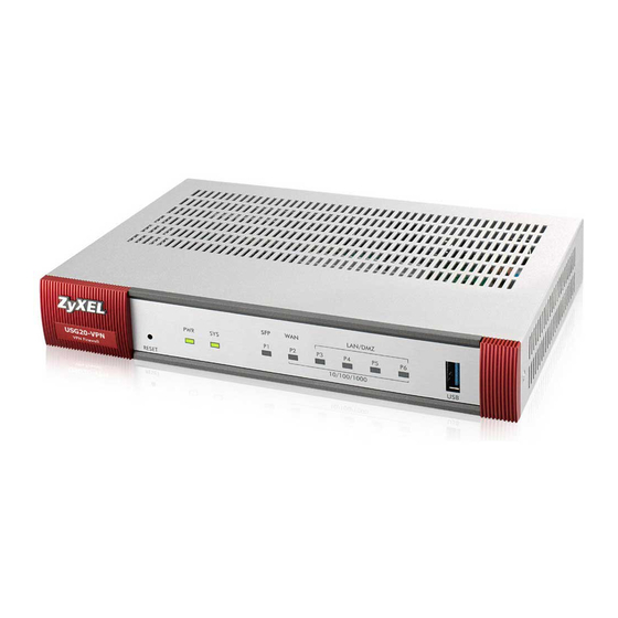
H A PT ER Hardware, Interfaces and Zones 3.1 Hardware Overview USG20-VPN and USG20W-VPN have different housings. 3.1.1 Front Panels The LED indicators are located on the front panel. Figure 31 USG20-VPN Front Panel Figure 32 USG20W-VPN Front Panel The following table describes the LEDs. Table 10 LED Descriptions COLOR STATUS DESCRIPTION... -
Page 46: Rear Panels
Chapter 3 Hardware, Interfaces and Zones Table 10 LED Descriptions (continued) COLOR STATUS DESCRIPTION WLAN Green The built-in wireless LAN card is not ready or has failed. The built-in wireless LAN card is ready. Blinking The built-in wireless LAN card is sending or receiving packets. P1, P2... -
Page 47: Wall-Mounting
Chapter 3 Hardware, Interfaces and Zones Table 11 Rear Panel Items (continued) LABEL DESCRIPTION WAN/LAN/DMZ/ P1- You have to install an SFP (Small Form-factor Pluggable) transceiver and connect fiber optic cables to it for using a 1Gbps/100Mbps WAN connection. (Gigabit SFP/ Ethernet Port) P2~P6 - Connect an Ethernet cable to the port for using a 1Gbps WAN/LAN/DMZ connection. -
Page 48: Default Zones, Interfaces, And Ports
Chapter 3 Hardware, Interfaces and Zones Figure 35 Wall Mounting Screw Specifications 3.2 Default Zones, Interfaces, and Ports The default configurations for zones, interfaces, and ports are as follows. References to interfaces may be generic rather than the specific name used in your model. For example, this guide may use “the WAN interface”... -
Page 49: Stopping The Usg
Chapter 3 Hardware, Interfaces and Zones The following table shows the default interface and zone mapping for each model at the time of writing. Table 13 Default Zone - Interface Mapping ZONE / INTERFACE LAN1 LAN2 • USG20-VPN LAN1 LAN2 WAN_PPP SFP_PPP •... -
Page 50: Chapter 4 Quick Setup Wizards
H A PT ER Quick Setup Wizards 4.1 Quick Setup Overview The Web Configurator's quick setup wizards help you configure Internet and VPN connection settings. This chapter provides information on configuring the quick setup screens in the Web Configurator. See the feature-specific chapters in this User’s Guide for background information. In the Web Configurator, click Configuration >... -
Page 51: Wan Interface Quick Setup
Chapter 4 Quick Setup Wizards • Wizard Help If the help does not automatically display when you run the wizard, click teh arrow to display it. 4.2 WAN Interface Quick Setup Click WAN Interface in the main Quick Setup screen to open the WAN Interface Quick Setup Wizard Welcome screen. -
Page 52: Select Wan Type
Chapter 4 Quick Setup Wizards Figure 38 Choose an Ethernet Interface 4.2.2 Select WAN Type WAN Type Selection: Select the type of encapsulation this connection is to use. Choose Ethernet when the WAN port is used as a regular Ethernet. Otherwise, choose PPPoE or PPTP for a dial-up connection according to the information from your ISP. -
Page 53: Isp And Wan And Isp Connection Settings
Chapter 4 Quick Setup Wizards Figure 40 WAN Interface Setup: Step 2 Dynamic IP Figure 41 WAN Interface Setup: Step 2 Fixed IP • WAN Interface: This is the interface you are configuring for Internet access. • Zone: This is the security zone to which this interface and Internet connection belong. •... - Page 54 Chapter 4 Quick Setup Wizards Figure 42 WAN and ISP Connection Settings: (PPTP Shown) The following table describes the labels in this screen. Table 14 WAN and ISP Connection Settings LABEL DESCRIPTION ISP Parameter This section appears if the interface uses a PPPoE or PPTP Internet connection. Encapsulation This displays the type of Internet connection you are configuring.
-
Page 55: Quick Setup Interface Wizard: Summary
Chapter 4 Quick Setup Wizards Table 14 WAN and ISP Connection Settings (continued) LABEL DESCRIPTION Idle Timeout Type the time in seconds that elapses before the router automatically disconnects from the PPPoE server. 0 means no timeout. PPTP Configuration This section only appears if the interface uses a PPPoE or PPTP Internet connection. Base Interface This displays the identity of the Ethernet interface you configure to connect with a modem or router. -
Page 56: Vpn Setup Wizard
Chapter 4 Quick Setup Wizards Figure 43 Interface Wizard: Summary WAN (PPTP Shown) The following table describes the labels in this screen. Table 15 Interface Wizard: Summary WAN LABEL DESCRIPTION Encapsulation This displays what encapsulation this interface uses to connect to the Internet. Service Name This field only appears for a PPPoE interface. -
Page 57: Welcome
Chapter 4 Quick Setup Wizards Figure 44 VPN Setup Wizard 4.3.1 Welcome Use wizards to create Virtual Private Network (VPN) rules. After you complete the wizard, the Phase 1 rule settings appear in the VPN > IPSec VPN > VPN Gateway screen and the Phase 2 rule settings appear in the VPN >... -
Page 58: Vpn Setup Wizard: Wizard Type
Chapter 4 Quick Setup Wizards 4.3.2 VPN Setup Wizard: Wizard Type Choose Express to create a VPN rule with the default phase 1 and phase 2 settings to connect to another ZLD-based USG using a pre-shared key. Choose Advanced to change the default settings and/or use certificates instead of a pre-shared key to create a VPN rule to connect to another IPSec device. - Page 59 Chapter 4 Quick Setup Wizards Figure 47 VPN Express Wizard: Scenario Rule Name: Type the name used to identify this VPN connection (and VPN gateway). You may use 1-31 alphanumeric characters, underscores (_), or dashes (-), but the first character cannot be a number.
-
Page 60: Vpn Express Wizard - Configuration
Chapter 4 Quick Setup Wizards 4.3.4 VPN Express Wizard - Configuration Figure 48 VPN Express Wizard: Configuration • Secure Gateway: Any displays in this field if it is not configurable for the chosen scenario. Otherwise, enter the WAN IP address or domain name of the remote IPSec device (secure gateway) to identify the remote IPSec router by its IP address or a domain name. -
Page 61: Vpn Express Wizard - Finish
Chapter 4 Quick Setup Wizards Figure 49 VPN Express Wizard: Summary • Rule Name: Identifies the VPN gateway policy. • Secure Gateway: IP address or domain name of the remote IPSec device. If this field displays Any, only the remote IPSec device can initiate the VPN connection. •... -
Page 62: Vpn Advanced Wizard - Scenario
Chapter 4 Quick Setup Wizards Figure 50 VPN Express Wizard: Finish Click Close to exit the wizard. 4.3.7 VPN Advanced Wizard - Scenario Click the Advanced radio button as shown in Figure 46 on page 58 to display the following screen. USG20(W)-VPN Series User’s Guide... -
Page 63: Vpn Advanced Wizard - Phase 1 Settings
Chapter 4 Quick Setup Wizards Figure 51 VPN Advanced Wizard: Scenario Rule Name: Type the name used to identify this VPN connection (and VPN gateway). You may use 1-31 alphanumeric characters, underscores (_), or dashes (-), but the first character cannot be a number. - Page 64 Chapter 4 Quick Setup Wizards Figure 52 VPN Advanced Wizard: Phase 1 Settings • Secure Gateway: Any displays in this field if it is not configurable for the chosen scenario. Otherwise, enter the WAN IP address or domain name of the remote IPSec device (secure gateway) to identify the remote IPSec device by its IP address or a domain name.
-
Page 65: Vpn Advanced Wizard - Phase 2
Chapter 4 Quick Setup Wizards Note: The remote IPSec device must also have NAT traversal enabled. See the help in the main IPSec VPN screens for more information. • Dead Peer Detection (DPD) has the USG make sure the remote IPSec device is there before transmitting data through the IKE SA. -
Page 66: Vpn Advanced Wizard - Summary
Chapter 4 Quick Setup Wizards 4.3.10 VPN Advanced Wizard - Summary This is a read-only summary of the VPN tunnel settings. Figure 54 VPN Advanced Wizard: Summary • Rule Name: Identifies the VPN connection (and the VPN gateway). • Secure Gateway: IP address or domain name of the remote IPSec device. •... -
Page 67: Vpn Settings For Configuration Provisioning Wizard: Wizard Type
Chapter 4 Quick Setup Wizards Figure 55 VPN Wizard: Finish Click Close to exit the wizard. 4.4 VPN Settings for Configuration Provisioning Wizard: Wizard Type Use VPN Settings for Configuration Provisioning to set up a VPN rule that can be retrieved with the USG IPSec VPN Client. -
Page 68: Configuration Provisioning Express Wizard - Vpn Settings
Chapter 4 Quick Setup Wizards Choose Express to create a VPN rule with the default phase 1 and phase 2 settings and to use a pre-shared key. Choose Advanced to change the default settings and/or use certificates instead of a pre-shared key in the VPN rule. -
Page 69: Configuration Provisioning Vpn Express Wizard - Configuration
Chapter 4 Quick Setup Wizards Figure 57 VPN for Configuration Provisioning Express Wizard: Settings Scenario Rule Name: Type the name used to identify this VPN connection (and VPN gateway). You may use 1-31 alphanumeric characters, underscores (_), or dashes (-), but the first character cannot be a number. -
Page 70: Vpn Settings For Configuration Provisioning Express Wizard - Summary
Chapter 4 Quick Setup Wizards Figure 58 VPN for Configuration Provisioning Express Wizard: Configuration • Secure Gateway: Any displays in this field because it is not configurable in this wizard. It allows incoming connections from the USG IPSec VPN Client. •... -
Page 71: Vpn Settings For Configuration Provisioning Express Wizard - Finish
Chapter 4 Quick Setup Wizards Figure 59 VPN for Configuration Provisioning Express Wizard: Summary • Rule Name: Identifies the VPN gateway policy. • Secure Gateway: Any displays in this field because it is not configurable in this wizard. It allows incoming connections from the USG IPSec VPN Client. -
Page 72: Vpn Settings For Configuration Provisioning Advanced Wizard - Scenario
Chapter 4 Quick Setup Wizards Figure 60 VPN for Configuration Provisioning Express Wizard: Finish Click Close to exit the wizard. 4.4.5 VPN Settings for Configuration Provisioning Advanced Wizard - Scenario Click the Advanced radio button as shown in the screen shown in Figure 56 on page 68 to display the following screen. -
Page 73: Vpn Settings For Configuration Provisioning Advanced Wizard - Phase 1 Settings
Chapter 4 Quick Setup Wizards Figure 61 VPN for Configuration Provisioning Advanced Wizard: Scenario Settings Rule Name: Type the name used to identify this VPN connection (and VPN gateway). You may use 1-31 alphanumeric characters, underscores (_), or dashes (-), but the first character cannot be a number. - Page 74 Chapter 4 Quick Setup Wizards Figure 62 VPN for Configuration Provisioning Advanced Wizard: Phase 1 Settings • Secure Gateway: Any displays in this field because it is not configurable in this wizard. It allows incoming connections from the USG IPSec VPN Client. •...
-
Page 75: Vpn Settings For Configuration Provisioning Advanced Wizard - Phase 2
Chapter 4 Quick Setup Wizards 4.4.7 VPN Settings for Configuration Provisioning Advanced Wizard - Phase Phase 2 in an IKE uses the SA that was established in phase 1 to negotiate SAs for IPSec. Figure 63 VPN for Configuration Provisioning Advanced Wizard: Phase 2 Settings •... - Page 76 Chapter 4 Quick Setup Wizards Figure 64 VPN for Configuration Provisioning Advanced Wizard: Summary Summary • Rule Name: Identifies the VPN connection (and the VPN gateway). • Secure Gateway: Any displays in this field because it is not configurable in this wizard. It allows incoming connections from the USG IPSec VPN Client.
-
Page 77: Vpn Settings For Configuration Provisioning Advanced Wizard- Finish
Chapter 4 Quick Setup Wizards • Encryption Algorithm: This displays the encryption method used. The longer the key, the higher the security, the lower the throughput (possibly). • DES uses a 56-bit key. • 3DES uses a 168-bit key. • AES128 uses a 128-bit key •... -
Page 78: Vpn Settings For L2Tp Vpn Settings Wizard
Chapter 4 Quick Setup Wizards Connection screen. Enter the IP address of the USG in the USG IPSec VPN Client to get all these VPN settings automatically from the USG. Figure 65 VPN for Configuration Provisioning Advanced Wizard: Finish Click Close to exit the wizard. 4.5 VPN Settings for L2TP VPN Settings Wizard Use VPN Settings for L2TP VPN Settings to set up an L2TP VPN rule. -
Page 79: L2Tp Vpn Settings
Chapter 4 Quick Setup Wizards Figure 66 VPN Settings for L2TP VPN Settings Wizard: L2TP VPN Settings Click Next to continue the wizard. 4.5.1 L2TP VPN Settings Figure 67 VPN Settings for L2TP VPN Settings Wizard: L2TP VPN Settings • Rule Name: Type the name used to identify this L2TP VPN connection (and L2TP VPN gateway). You may use 1-31 alphanumeric characters, underscores (_), or dashes (-), but the first character cannot be a number. -
Page 80: L2Tp Vpn Settings
Chapter 4 Quick Setup Wizards • My Address (interface): Select one of the interfaces from the pull down menu to apply the L2TP VPN rule. • Pre-Shared Key: Type the password. Both ends of the VPN tunnel must use the same password. Use 8 to 31 case-sensitive ASCII characters or 8 to 31 pairs of hexadecimal (“0-9”, “A-F”) characters. -
Page 81: Vpn Settings For L2Tp Vpn Setting Wizard - Summary
Chapter 4 Quick Setup Wizards Note: DNS (Domain Name System) is for mapping a domain name to its corresponding IP address and vice versa. The DNS server is extremely important because without it, you must know the IP address of a computer before you can access it. The USG uses a system DNS server (in the order you specify here) to resolve domain names for VPN, DDNS and the time server. -
Page 82: Vpn Settings For L2Tp Vpn Setting Wizard Completed
Chapter 4 Quick Setup Wizards 4.5.4 VPN Settings for L2TP VPN Setting Wizard Completed Figure 70 VPN Settings for L2TP VPN Settings Wizard: Finish Now the rule is configured on the USG. The L2TP VPN rule settings appear in the VPN > L2TP VPN screen and also in the VPN >... -
Page 83: Dashboard
H A PT ER Dashboard 5.1 Overview Use the Dashboard screens to check status information about the USG. 5.1.1 What You Can Do in this Chapter Use the main Dashboard screen to see the USG’s general device information, system status, system resource usage, licensed service status, and interface status. - Page 84 Chapter 5 Dashboard Click on the icon to go to the OneSecurity.com website where there is guidance on configuration walkthroughs, troubleshooting, and other information. Figure 71 Dashboard The following table describes the labels in this screen. Table 16 Dashboard LABEL DESCRIPTION Widget Settings Use this link to open or close widgets by selecting/clearing the associated checkbox.
-
Page 85: Device Information Screen
Chapter 5 Dashboard Table 16 Dashboard (continued) LABEL DESCRIPTION Front Panel Click this to view details about the status of the USG’s front panel LEDs and connections. Section 3.1.1 on page 45 for LED descriptions. An unconnected interface or slot appears grayed out. -
Page 86: System Status Screen
Chapter 5 Dashboard This tabel describes the fields in the above screen. Table 17 Dashboard > Device Information LABEL DESCRIPTION Device Information This identifies a device installed in one of the USG’s extension slots, the Security Extension Module slot, or USB ports. For an installed SEM (Security Extension Module) card, this field displays what kind of SEM card is installed. -
Page 87: Vpn Status Screen
Chapter 5 Dashboard Table 18 Dashboard > System Status LABEL DESCRIPTION DHCP Table Click this to look at the IP addresses currently assigned to the USG’s DHCP clients and the IP addresses reserved for specific MAC addresses. See Section 5.2.4 on page Current Login User This field displays the user name used to log in to the current session, the amount of reauthentication time remaining, and the amount of lease time... -
Page 88: Dhcp Table Screen
Chapter 5 Dashboard Table 19 Dashboard > System Status > VPN Status LABLE DESCRIPTION This field is a sequential value, and it is not associated with a specific SA. Name This field displays the name of the IPSec SA. Encapsulation This field displays how the IPSec SA is encapsulated. -
Page 89: Number Of Login Users Screen
Chapter 5 Dashboard Figure 75 Dashboard > System Status > DHCP Table This table describes the fields in the above screen. Table 20 Dashboard > System Status > DHCP Table LABEL DESCRIPTION This field is a sequential value, and it is not associated with a specific entry. Interface This field identifies the interface that assigned an IP address to a DHCP client. -
Page 90: System Resources Screen
Chapter 5 Dashboard Figure 76 Dashboard > System Status > Number of Login Users This table describes the fields in the above screen. Table 21 Dashboard > System Status > Number of Login Users LABEL DESCRIPTION This field is a sequential value and is not associated with any entry. User ID This field displays the user name of each user who is currently logged in to the USG. -
Page 91: Cpu Usage Screen
Chapter 5 Dashboard Figure 77 Dashboard > System Resources This table describes the fields in the above screen. Table 22 .Dashboard > System Resources LABEL DESCRIPTION CPU Usage This field displays what percentage of the USG’s processing capability is currently being used. Hover your cursor over this field to display the Show CPU Usage icon that takes you to a chart of the USG’s recent CPU usage. -
Page 92: Memory Usage Screen
Chapter 5 Dashboard Figure 78 Dashboard > CPU Usage screen This table describes the fields in the above screen. Table 23 Dashboard > CPU Usage LABEL DESCRIPTION The y-axis represents the percentage of CPU usage. The x-axis shows the time period over which the CPU usage occurred Refresh Interval Enter how often you want this window to be automatically updated. -
Page 93: Active Session Screen
Chapter 5 Dashboard This table describes the fields in the above screen. Table 24 Dashboard > Memory Usage screen. LABEL DESCRIPTION The y-axis represents the percentage of RAM usage. The x-axis shows the time period over which the RAM usage occurred Refresh Interval Enter how often you want this window to be automatically updated. -
Page 94: Extension Slot Screen
Chapter 5 Dashboard 5.2.10 Extension Slot Screen Figure 81 Dashboard > Extension Slot This table describes the fields in the above screen. Table 26 Dashboard > Extension Slot LABEL DESCRIPTION Extension Slot This field displays the name of each extension slot. Device This field displays the name of the device connected to the extension slot (or none if no device is detected). -
Page 95: Secured Service Status Screen
Chapter 5 Dashboard This table describes the fields in the above screen. Table 27 Dashboard > Interface Status Summary LABEL DESCRIPTION Name This field displays the name of each interface. Status This field displays the current status of each interface. The possible values depend on what type of interface it is. -
Page 96: Content Filter Statistics Screen
Chapter 5 Dashboard Figure 83 Dashboard > Secured Service Status This table describes the fields in the above screen. Table 28 Dashboard > Secured Service Status LABEL DESCRIPTION This field is a sequential value, and it is not associated with a specific status. Status This field displays the status of the USG’s security services. -
Page 97: Top 5 Ipv4/Ipv6 Security Policy Rules That Blocked Traffic Screen
Chapter 5 Dashboard Table 29 Dashboard > Content Filter Statistics LABEL DESCRIPTION Blocked This is the number of web pages that the USG blocked access. Warned This is the number of web pages for which the USG has displayed a warning message to the access requesters. - Page 98 Chapter 5 Dashboard This table describes the fields in the above screen. Table 31 Dashboard > The Latest Alert Logs LABEL DESCRIPTION This is the entry’s rank in the list of alert logs. Time This field displays the date and time the log was created. Priority This field displays the severity of the log.
-
Page 99: Part Ii: Technical Reference
Technical Reference... -
Page 101: Chapter 6 Monitor
H A PT ER Monitor 6.1 Overview Use the Monitor screens to check status and statistics information. 6.1.1 What You Can Do in this Chapter Use the Monitor screens for the following. • Use the System Status > Port Statistics screen (see Section 6.2 on page 102) to look at packet statistics for each physical port. -
Page 102: The Port Statistics Screen
Chapter 6 Monitor • Use the VPN Monitor > IPSec screen (Section 6.15 on page 123) to display and manage active IPSec SAs. • Use the VPN Monitor > SSL screen (see Section 6.16 on page 124) to list the users currently logged into the VPN SSL client portal. -
Page 103: The Port Statistics Graph Screen
Chapter 6 Monitor Table 32 Monitor > System Status > Port Statistics (continued) LABEL DESCRIPTION This field is a sequential value, and it is not associated with a specific port. Port This field displays the physical port number. Status This field displays the current status of the physical port. Down - The physical port is not connected. -
Page 104: Interface Status Screen
Chapter 6 Monitor The following table describes the labels in this screen. Table 33 Monitor > System Status > Port Statistics > Switch to Graphic View LABEL DESCRIPTION Refresh Interval Enter how often you want this window to be automatically updated. Refresh Now Click this to update the information in the window right away. - Page 105 Chapter 6 Monitor Each field is described in the following table. Table 34 Monitor > System Status > Interface Status LABEL DESCRIPTION Interface Status If an Ethernet interface does not have any physical ports associated with it, its entry is displayed in light gray text.
-
Page 106: The Traffic Statistics Screen
Chapter 6 Monitor Table 34 Monitor > System Status > Interface Status (continued) LABEL DESCRIPTION Action Use this field to get or to update the IP address for the interface. Click Renew to send a new DHCP request to a DHCP server. Click Connect to try to connect a PPPoE/PPTP interface. - Page 107 Chapter 6 Monitor • LAN IP with heaviest traffic and how much traffic has been sent to and from each one You use the Traffic Statistics screen to tell the USG when to start and when to stop collecting information for these reports. You cannot schedule data collection; you have to start and stop it manually in the Traffic Statistics screen.
- Page 108 Chapter 6 Monitor Table 35 Monitor > System Status > Traffic Statistics (continued) LABEL DESCRIPTION Direction This field indicates whether the IP address or user is sending or receiving traffic. • Ingress- traffic is coming from the IP address or user to the USG. •...
-
Page 109: The Session Monitor Screen
Chapter 6 Monitor 6.5 The Session Monitor Screen The Session Monitor screen displays all established sessions that pass through the USG for debugging or statistical analysis. It is not possible to manage sessions in this screen. The following information is displayed. •... -
Page 110: Igmp Statistics
Chapter 6 Monitor Table 37 Monitor > System Status > Session Monitor (continued) LABEL DESCRIPTION Service This field displays when View is set to all sessions. Select the service or service group whose sessions you want to view. The USG identifies the service by comparing the protocol and destination port of each packet to the protocol and port of each services that is defined. -
Page 111: The Ddns Status Screen
Chapter 6 Monitor Figure 92 Monitor > System Status > IGMP Statistics The following table describes the labels in this screen. Table 38 Monitor > System Status > IGMP Statistics LABEL DESCRIPTION This field is a sequential value, and it is not associated with a specific I GMP Statistics. -
Page 112: Ip/Mac Binding
Chapter 6 Monitor Table 39 Monitor > System Status > DDNS Status (continued) LABEL DESCRIPTION Last Update Status This shows whether the last attempt to resolve the IP address for the domain name was successful or not. Updating means the USG is currently attempting to resolve the IP address for the domain name. -
Page 113: Cellular Status Screen
Chapter 6 Monitor Figure 95 Monitor > System Status > Login Users The following table describes the labels in this screen. Table 41 Monitor > System Status > Login Users LABEL DESCRIPTION Force Logout Select a user ID and click this icon to end a user’s session. This field is a sequential value and is not associated with any entry. - Page 114 Chapter 6 Monitor The following table describes the labels in this screen. Table 42 Monitor > System Status > Cellular Status LABEL DESCRIPTION Refresh Click this button to update the information in the screen. More Information Click this to display more information on your mobile broadband, such as the signal strength, IMEA/ESN and IMSI.
-
Page 115: The Upnp Port Status Screen
Chapter 6 Monitor Table 42 Monitor > System Status > Cellular Status (continued) LABEL DESCRIPTION Service Provider This displays the name of your network service provider. This shows Limited Service if the service provider has stopped service to the mobile broadband card. For example if the bill has not been paid or the account has expired. -
Page 116: Usb Storage Screen
Chapter 6 Monitor Table 43 Monitor > System Status > UPnP Port Status (continued) LABEL DESCRIPTION Internal Port This field displays the port number on the Internal Client to which the USG should forward incoming connection requests. Internal Client This field displays the DNS host name or IP address of a client on the LAN. Multiple NAT clients can use a single port simultaneously if the internal client field is set to 255.255.255.255 for UDP mappings. -
Page 117: Ethernet Neighbor Screen
Chapter 6 Monitor Table 44 Monitor > System Status > USB Storage (continued) LABEL DESCRIPTION Status Ready - you can have the USG use the USB storage device. Click Remove Now to stop the USG from using the USB storage device so you can remove it. -
Page 118: Wireless
Chapter 6 Monitor The following table describes the fields in the previous screen. Table 45 Monitor > System Status > Ethernet Neighbor LABEL DESCRIPTION Local Port (Description) This field displays the port of the USG, on which the neighboring device is discovered. - Page 119 Chapter 6 Monitor Table 46 Monitor > Wireless > Radio List LABEL DESCRIPTION Model This field displays the AP’s hardware model information. It displays N/A (not applicable) only when the AP disconnects from the USG and the information is unavailable as a result.
-
Page 120: Radio List More Information
Chapter 6 Monitor 6.14.2 Radio List More Information This screen allows you to view detailed information about a selected radio’s SSID(s), wireless traffic and wireless clients for the preceding 24 hours. To access this window, select an entry and click the More Information button in the Radio List screen. -
Page 121: Wireless Station Info
Chapter 6 Monitor The following table describes the labels in this screen. Table 47 Monitor > Wireless > AP Info > Radio List > More Information LABEL DESCRIPTION MBSSID Detail This list shows information about the SSID(s) that is associated with the radio. This is the items sequential number in the list. -
Page 122: Detected Device
Chapter 6 Monitor Table 48 Monitor > Wireless > Station List LABEL DESCRIPTION Signal Strength This field displays the signal strength of the station. The signal strength mainly depends on the antenna output power and the distance between the station and the AP. Channel This indicates the number the channel used by the station to connect to the network. -
Page 123: The Ipsec Monitor Screen
Chapter 6 Monitor Table 49 Monitor > Wireless > Detected Device (continued) LABEL DESCRIPTION Security This indicates the encryption method (if any) used by the detected device. Description This displays the detected device’s description. For more on managing friendly and rogue APs, see the Configuration >... -
Page 124: Regular Expressions In Searching Ipsec Sas
Chapter 6 Monitor Table 50 Monitor > VPN Monitor > IPSec (continued) LABEL DESCRIPTION Secure Gateway This field displays the secure gateway information. Up Time This field displays how many seconds the IPSec SA has been active. This field displays N/A if the IPSec SA uses manual keys. -
Page 125: The L2Tp Over Ipsec Session Monitor Screen
Chapter 6 Monitor Figure 105 Monitor > VPN Monitor > SSL The following table describes the labels in this screen. Table 51 Monitor > VPN Monitor > SSL LABEL DESCRIPTION Disconnect Select a connection and click this button to terminate the user’s connection and delete corresponding session information from the USG. -
Page 126: The Content Filter Screen
Chapter 6 Monitor Table 52 Monitor > VPN Monitor > L2TP over IPSec (continued) LABEL DESCRIPTION Hostname This field displays the name of the computer that has this L2TP VPN connection with the USG. Assigned IP This field displays the IP address that the USG assigned for the remote user’s computer to use within the L2TP VPN tunnel. - Page 127 Chapter 6 Monitor The following table describes the labels in this screen. Table 53 Monitor > UTM Statistics > Content Filter LABEL DESCRIPTION General Settings Collect Statistics Select this check box to have the USG collect content filtering statistics. The collection starting time displays after you click Apply. All of the statistics in this screen are for the time period starting at the time displayed here.
-
Page 128: The Anti-Spam Screens
Chapter 6 Monitor 6.19 The Anti-Spam Screens The Anti-Spam menu contains the Report and Status screens. 6.19.1 Anti-Spam Report Click Monitor > UTM Statistics > Anti-Spam to display the following screen. This screen displays spam statistics. Figure 108 Monitor > UTM Statistics > Anti-Spam The following table describes the labels in this screen. - Page 129 Chapter 6 Monitor Table 54 Monitor > UTM Statistics > Anti-Spam (continued) LABEL DESCRIPTION Flush Data Click this button to discard all of the screen’s statistics and update the report display. Total Mails Scanned This field displays the number of e-mails that the USG’s anti-spam feature has checked.
-
Page 130: The Anti-Spam Status Screen
Chapter 6 Monitor Table 54 Monitor > UTM Statistics > Anti-Spam (continued) LABEL DESCRIPTION Sender Email Address This column displays when you display the entries by Sender Email Address. This column displays the e-mail addresses from which the USG has detected the most spam. -
Page 131: Log Screens
Chapter 6 Monitor Table 55 Monitor > UTM Statistics > Anti-Spam > Status (continued) LABEL DESCRIPTION Avg. Response Time (sec) This is the average for how long it takes to receive a reply from this service. No Response This is how many queries the USG sent to this service without receiving a reply. DNSBL Statistics These are the statistics for the DNSBL the USG uses. - Page 132 Chapter 6 Monitor Figure 110 Monitor > Log > View Log The following table describes the labels in this screen. Table 56 Monitor > Log > View Log LABEL DESCRIPTION Show Filter Click this button to show or hide the filter settings. If the filter settings are hidden, the Display, Email Log Now, Refresh, and Clear Log fields are available.
- Page 133 Chapter 6 Monitor Table 56 Monitor > Log > View Log (continued) LABEL DESCRIPTION Priority This field displays the priority of the log message. It has the same range of values as the Priority field above. Source This field displays the source IP address and the port number in the event that generated the log message.
-
Page 134: Chapter 7 Licensing
H A PT ER Licensing 7.1 Registration Overview Use the Configuration > Licensing > Registration screens to register your USG and manage its service subscriptions. • Use the Registration screen (see Section 7.1.2 on page 135) to go to portal.myzyxel.com to register your USG and activate a service, such as content filtering. -
Page 135: Registration Screen
Chapter 7 Licensing 7.1.2 Registration Screen Click the link in this screen to register your USG at myZyXEL.com. The USG should already have Internet access before you can access it. Click Configuration > Licensing > Registration in the navigation panel to open the screen as shown next. Click on the icon to go to the OneSecurity.com website where there is guidance on configuration walkthrough and other information. - Page 136 Chapter 7 Licensing Table 57 Configuration > Licensing > Registration > Service (continued) LABEL DESCRIPTION Expiration Date This field displays the date your service expires. Count This field displays how many VPN tunnels you can use with your current license. This field does not apply to the other services. Service License Refresh Click this button to renew service license information (such as the registration status and expiration day).
-
Page 137: Chapter 8 Wireless
H A PT ER Wireless 8.1 Overview Use the Wireless screens to configure how the USG manages the Access Points (APs) that are connected to it. 8.1.1 What You Can Do in this Chapter • The AP Management screen (Section 8.2 on page 138) manages all of the APs connected to the USG. -
Page 138: Ap Management Screen
Chapter 8 Wireless 8.2 AP Management Screen Use this screen to manage the USG’s general wireless settings. Click Configuration > Wireless > AP Management to access this screen. Figure 113 Configuration > Wireless > AP Management Each field is described in the following table. Table 58 Configuration >... -
Page 139: Dcs Screen
Chapter 8 Wireless Table 58 Configuration > Wireless > AP Management (continued) LABEL DESCRIPTION Apply Click Apply to save your changes back to the USG. Reset Click Reset to close the window with changes unsaved. 8.3 DCS Screen Use this screen to configure dynamic radio channel selection. Click Configuration > Wireless > DCS to access this screen. - Page 140 Chapter 8 Wireless Figure 115 An Example Three-Channel Deployment Three channels are situated in such a way as to create almost no interference with one another if used exclusively: 1, 6 and 11. When an AP broadcasts on any of these three channels, it should not interfere with neighboring APs as long as they are also limited to same trio.
-
Page 141: Interfaces
H A PT ER Interfaces 9.1 Interface Overview Use the Interface screens to configure the USG’s interfaces. You can also create interfaces on top of other interfaces. • Ports are the physical ports to which you connect cables. • Interfaces are used within the system operationally. You use them in configuring various features. -
Page 142: What You Need To Know
Chapter 9 Interfaces 9.1.2 What You Need to Know Interface Characteristics Interfaces generally have the following characteristics (although not all characteristics apply to each type of interface). • An interface is a logical entity through which (layer-3) packets pass. • An interface is bound to a physical port or another interface. •... - Page 143 Chapter 9 Interfaces characteristics. These characteristics are listed in the following table and discussed in more detail below. Table 60 Ethernet, PPP, Cellular, VLAN, Bridge, and Virtual Interface Characteristics CHARACTERISTICS ETHERNET ETHERNET CELLULAR VLAN BRIDGE VIRTUAL Name* wan1, wan2 lan1, lan2, pppx cellularx vlanx...
- Page 144 Chapter 9 Interfaces Table 61 Relationships Between Different Types of Interfaces (continued) INTERFACE REQUIRED PORT / INTERFACE PPP interface Ethernet interface* VLAN interface* bridge interface WAN1, WAN2, OPT* virtual interface (virtual Ethernet interface) Ethernet interface* (virtual VLAN interface) VLAN interface* (virtual bridge interface) bridge interface trunk...
- Page 145 Chapter 9 Interfaces compose the network address. The prefix length is written as “/x” where x is a number. For example, 2001:db8:1a2b:15::1a2f:0/32 means that the first 32 bits (2001:db8) from the left is the network prefix. Link-local Address A link-local address uniquely identifies a device on the local network (the LAN). It is similar to a “private IP address”...
-
Page 146: What You Need To Do First
Chapter 9 Interfaces IPv6 Router Advertisement An IPv6 router sends router advertisement messages periodically to advertise its presence and other parameters to the hosts in the same network. DHCPv6 The Dynamic Host Configuration Protocol for IPv6 (DHCPv6, RFC 3315) is a server-client protocol that allows a DHCP server to assign and pass IPv6 network addresses, prefixes and other configuration information to DHCP clients. -
Page 147: Ethernet Summary Screen
Chapter 9 Interfaces Figure 118 Configuration > Network > Interface > Port Role Physical Ports Default interface (ZONE) The physical Ethernet ports are shown at the top and the Ethernet interfaces and zones are shown at the bottom of the screen. Use the radio buttons to select for which interface (network) you want to use each physical port. - Page 148 Chapter 9 Interfaces Ethernet interfaces are similar to other types of interfaces in many ways. They have an IP address, subnet mask, and gateway used to make routing decisions. They restrict the amount of bandwidth and packet size. They can provide DHCP services, and they can verify the gateway is available. Use Ethernet interfaces to control which physical ports exchange routing information with other routers and how much information is exchanged through each one.
-
Page 149: Ethernet Edit
Chapter 9 Interfaces Table 63 Configuration > Network > Interface > Ethernet (continued) LABEL DESCRIPTION IP Address This field displays the current IP address of the interface. If the IP address is 0.0.0.0 (in the IPv4 network) or :: (in the IPv6 network), the interface does not have an IP address yet. -
Page 150: Igmp Proxy
Chapter 9 Interfaces Set the priority used to identify the DR or BDR if one does not exist. IGMP Proxy Internet Group Management Protocol (IGMP) proxy is used for multicast routing. IGMP proxy enables the to issue IGMP host messages on behalf of hosts that the discovered on its IGMP-enabled interfaces. - Page 151 Chapter 9 Interfaces • Configuration > Network > Interface > Ethernet > Edit (External Type) USG20(W)-VPN Series User’s Guide...
- Page 152 Chapter 9 Interfaces Configuration > Network > Interface > Ethernet > Edit (External Type USG20(W)-VPN Series User’s Guide...
- Page 153 Chapter 9 Interfaces Figure 120 Configuration > Network > Interface > Ethernet > Edit (Internal Type) USG20(W)-VPN Series User’s Guide...
- Page 154 Chapter 9 Interfaces Configuration > Network > Interface > Ethernet > Edit (Internal Type) USG20(W)-VPN Series User’s Guide...
- Page 155 Chapter 9 Interfaces Figure 121 Configuration > Network > Interface > Ethernet > Edit (OPT) USG20(W)-VPN Series User’s Guide...
- Page 156 Chapter 9 Interfaces Configuration > Network > Interface > Ethernet > Edit (OPT) USG20(W)-VPN Series User’s Guide...
- Page 157 Chapter 9 Interfaces This screen’s fields are described in the table below. Table 64 Configuration > Network > Interface > Ethernet > Edit LABEL DESCRIPTION IPv4/IPv6 View / Use this button to display both IPv4 and IPv6, IPv4-only, or IPv6-only configuration IPv4 View / IPv6 fields.
- Page 158 Chapter 9 Interfaces Table 64 Configuration > Network > Interface > Ethernet > Edit (continued) LABEL DESCRIPTION Gateway This option appears when Interface Type is external or general. Enter the IP address of the gateway. The USG sends packets to the gateway when it does not know how to route the packet to its destination.
- Page 159 Chapter 9 Interfaces Table 64 Configuration > Network > Interface > Ethernet > Edit (continued) LABEL DESCRIPTION Suffix Enter the ending part of the IPv6 address, a slash (/), and the prefix length. The USG Address will append it to the delegated prefix. For example, you got a delegated prefix of 2003:1234:5678/48.
- Page 160 Chapter 9 Interfaces Table 64 Configuration > Network > Interface > Ethernet > Edit (continued) LABEL DESCRIPTION Advertised Hosts Select this to have the USG indicate to hosts to obtain network settings (such as prefix Get Network and DNS settings) through DHCPv6. Configuration From DHCPv6 Clear this to have the USG indicate to hosts that DHCPv6 is not available and they...
- Page 161 Chapter 9 Interfaces Table 64 Configuration > Network > Interface > Ethernet > Edit (continued) LABEL DESCRIPTION Address This is the final network prefix combined by the delegated prefix and the suffix. Note: This field displays the combined address after you click OK and reopen this screen.
- Page 162 Chapter 9 Interfaces Table 64 Configuration > Network > Interface > Ethernet > Edit (continued) LABEL DESCRIPTION Relay Server 1 Enter the IP address of a DHCP server for the network. Relay Server 2 This field is optional. Enter the IP address of another DHCP server for the network. These fields appear if the USG is a DHCP Server.
- Page 163 Chapter 9 Interfaces Table 64 Configuration > Network > Interface > Ethernet > Edit (continued) LABEL DESCRIPTION Value This is the value set for the DHCP option. Enable IP/MAC Select this option to have this interface enforce links between specific IP addresses and Binding specific MAC addresses.
-
Page 164: Object References
Chapter 9 Interfaces Table 64 Configuration > Network > Interface > Ethernet > Edit (continued) LABEL DESCRIPTION Authentication Select an authentication method, or disable authentication. To exchange OSPF routing information with peer border routers, you must use the same authentication method that they use. -
Page 165: Add/Edit Dhcpv6 Request/Release Options
Chapter 9 Interfaces Figure 122 Object References The following table describes labels that can appear in this screen. Table 65 Object References LABEL DESCRIPTION Object Name This identifies the object for which the configuration settings that use it are displayed. Click the object’s name to display the object’s configuration screen in the main window. -
Page 166: Add/Edit Dhcp Extended Options
Chapter 9 Interfaces Select a DHCPv6 request or lease object in the Select one object field and click OK to save it. Click Cancel to exit without saving the setting. 9.3.4 Add/Edit DHCP Extended Options When you configure an interface as a DHCPv4 server, you can additionally add DHCP extended options which have the USG to add more information in the DHCP packets. -
Page 167: Ppp Interfaces
Chapter 9 Interfaces Table 66 Configuration > Network > Interface > Ethernet > Edit > Add/Edit Extended Options LABEL DESCRIPTION First If you selected VIVS (125), enter additional information for the corresponding enterprise Information, number in these fields. Second Information Click this to close this screen and update the settings to the previous Edit screen. -
Page 168: Ppp Interface Summary
Chapter 9 Interfaces Figure 125 Example: PPPoE/PPTP Interfaces PPPoE/PPTP interfaces are similar to other interfaces in some ways. They have an IP address, subnet mask, and gateway used to make routing decisions; they restrict bandwidth and packet size; and they can verify the gateway is available. There are two main differences between PPPoE/ PPTP interfaces and other interfaces. -
Page 169: Ppp Interface Add Or Edit
Chapter 9 Interfaces Each field is described in the table below. Table 68 Configuration > Network > Interface > PPP LABEL DESCRIPTION User Configuration / The USG comes with the (non-removable) System Default PPP interfaces pre- System Default configured. You can create (and delete) User Configuration PPP interfaces. System Default PPP interfaces vary by model. - Page 170 Chapter 9 Interfaces Figure 127 Configuration > Network > Interface > PPP > Add USG20(W)-VPN Series User’s Guide...
- Page 171 Chapter 9 Interfaces Each field is explained in the following table. Table 69 Configuration > Network > Interface > PPP > Add LABEL DESCRIPTION IPv4/IPv6 View / Use this button to display both IPv4 and IPv6, IPv4-only, or IPv6-only configuration IPv4 View / IPv6 fields.
- Page 172 Chapter 9 Interfaces Table 69 Configuration > Network > Interface > PPP > Add (continued) LABEL DESCRIPTION IP Address This field is enabled if you select Use Fixed IP Address. Enter the IP address for this interface. Metric Enter the priority of the gateway (the ISP) on this interface. The USG decides which gateway to use based on this priority.
- Page 173 Chapter 9 Interfaces Table 69 Configuration > Network > Interface > PPP > Add (continued) LABEL DESCRIPTION Enable Rapid Select this to shorten the DHCPv6 message exchange process from four to two steps. Commit This function helps reduce heavy network traffic load. Note: Make sure you also enable this option in the DHCPv6 clients to make rapid commit work.
-
Page 174: Cellular Configuration Screen
Chapter 9 Interfaces Table 69 Configuration > Network > Interface > PPP > Add (continued) LABEL DESCRIPTION Check Port This field only displays when you set the Check Method to tcp. Specify the port number to use for a TCP connectivity check. Related Setting Configure WAN Click WAN TRUNK to go to a screen where you can configure the interface as part of a... - Page 175 Chapter 9 Interfaces See the following table for a comparison between 2G, 2.5G, 2.75G, 3G and 4G wireless technologies. Table 70 2G, 2.5G, 2.75G, 3G, 3.5G and 4G Wireless Technologies MOBILE PHONE AND DATA STANDARDS DATA NAME TYPE SPEED GSM-BASED CDMA-BASED Circuit- GSM (Global System for Mobile...
- Page 176 Chapter 9 Interfaces Figure 128 Configuration > Network > Interface > Cellular The following table describes the labels in this screen. Table 71 Configuration > Network > Interface > Cellular LABEL DESCRIPTION Click this to create a new cellular interface. Edit Double-click an entry or select it and click Edit to open a screen where you can modify the entry’s settings.
-
Page 177: Cellular Choose Slot
Chapter 9 Interfaces Table 71 Configuration > Network > Interface > Cellular (continued) LABEL DESCRIPTION Current This displays the currently supported (by the USG) mobile broadband dongle list version Version number. Update Now If the latest version number is greater than the current version number, then click this button to download the latest list of supported mobile broadband dongle devices to the USG. - Page 178 Chapter 9 Interfaces Figure 129 Configuration > Network > Interface > Cellular > Add / Edit USG20(W)-VPN Series User’s Guide...
- Page 179 Chapter 9 Interfaces The following table describes the labels in this screen. Table 72 Configuration > Network > Interface > Cellular > Add / Edit LABEL DESCRIPTION Show Advanced Click this button to display a greater or lesser number of configuration fields. Settings / Hide Advanced Settings General Settings...
- Page 180 Chapter 9 Interfaces Table 72 Configuration > Network > Interface > Cellular > Add / Edit (continued) LABEL DESCRIPTION User Name This field displays when you select an authentication type other than None. This field is read-only if you selected Device in the profile selection. If this field is configurable, enter the user name for this mobile broadband card exactly as the service provider gave it to you.
- Page 181 Chapter 9 Interfaces Table 72 Configuration > Network > Interface > Cellular > Add / Edit (continued) LABEL DESCRIPTION Check Period Enter the number of seconds between connection check attempts. Check Timeout Enter the number of seconds to wait for a response before the attempt is a failure. Check Fail Enter the number of consecutive failures before the USG stops routing through the Tolerance...
- Page 182 Chapter 9 Interfaces Table 72 Configuration > Network > Interface > Cellular > Add / Edit (continued) LABEL DESCRIPTION Network Home network is the network to which you are originally subscribed. Selection Select Home to have the mobile broadband device connect only to the home network. If the home network is down, the USG’s mobile broadband Internet connection is also unavailable.
-
Page 183: Tunnel Interfaces
Chapter 9 Interfaces Table 72 Configuration > Network > Interface > Cellular > Add / Edit (continued) LABEL DESCRIPTION Actions when over Specify the actions the USG takes when the specified percentage of time budget or % of time budget or data limit is exceeded. - Page 184 Chapter 9 Interfaces IPv6-in-IPv4 Tunneling Use this mode on the WAN of the USG if • your USG has a public IPv4 IP address given from your ISP, • you want to transmit your IPv6 packets to one and only one remote site whose LAN network is also an IPv6 network.
-
Page 185: Configuring A Tunnel
Chapter 9 Interfaces Figure 133 6to4 Tunnel IPv6 IPv6 IPv4 Internet IPv6 9.6.1 Configuring a Tunnel This screen lists the USG’s configured tunnel interfaces. To access this screen, click Network > Interface > Tunnel. Figure 134 Network > Interface > Tunnel Each field is explained in the following table. -
Page 186: Tunnel Add Or Edit Screen
Chapter 9 Interfaces Table 73 Network > Interface > Tunnel (continued) LABEL DESCRIPTION Status The activate (light bulb) icon is lit when the entry is active and dimmed when the entry is inactive. Name This field displays the name of the interface. IP Address This is the IP address of the interface. - Page 187 Chapter 9 Interfaces Figure 135 Network > Interface > Tunnel > Add/Edit Each field is explained in the following table. Table 74 Network > Interface > Tunnel > Add/Edit LABEL DESCRIPTION Show Advanced Click this button to display a greater or lesser number of configuration fields. Settings / Hide Advanced Settings General Settings...
- Page 188 Chapter 9 Interfaces Table 74 Network > Interface > Tunnel > Add/Edit (continued) LABEL DESCRIPTION Tunnel Mode Select the tunneling protocol of the interface (GRE, IPv6-in-IPv4 or 6to4). See Section 9.6 on page 183 for more information. IP Address This section is available if you are configuring a GRE tunnel. Assignment IP Address Enter the IP address for this interface.
-
Page 189: Vlan Interfaces
Chapter 9 Interfaces Table 74 Network > Interface > Tunnel > Add/Edit (continued) LABEL DESCRIPTION Interface Parameters Egress Enter the maximum amount of traffic, in kilobits per second, the USG can send through Bandwidth the interface to the network. Allowed values are 0 - 1048576. This setting is used in WAN load balancing and bandwidth management. - Page 190 Chapter 9 Interfaces Figure 136 Example: Before VLAN In this example, there are two physical networks and three departments A, B, and C. The physical networks are connected to hubs, and the hubs are connected to the router. Alternatively, you can divide the physical networks into three VLANs. Figure 137 Example: After VLAN Each VLAN is a separate network with separate IP addresses, subnet masks, and gateways.
-
Page 191: Vlan Summary Screen
Chapter 9 Interfaces • Higher security - If each computer has a separate physical connection to the switch, then broadcast traffic in each VLAN is never sent to computers in another VLAN. • Better manageability - You can align network policies more appropriately for users. For example, you can create different content filtering rules for each VLAN (each department in the example above), and you can set different bandwidth limits for each VLAN. - Page 192 Chapter 9 Interfaces Figure 138 Configuration > Network > Interface > VLAN Each field is explained in the following table. Table 75 Configuration > Network > Interface > VLAN LABEL DESCRIPTION Configuration Use the Configuration section for IPv4 network settings. Use the IPv6 Configuration / IPv6 section for IPv6 network settings if you connect your USG to an IPv6 network.
-
Page 193: Vlan Add/Edit
Chapter 9 Interfaces 9.7.2 VLAN Add/Edit Select an existing entry in the previous scrren and click Edit or click Add to create a new entry. The following screen appears. USG20(W)-VPN Series User’s Guide... - Page 194 Chapter 9 Interfaces Figure 139 Configuration > Network > Interface > VLAN > Add /Edit USG20(W)-VPN Series User’s Guide...
- Page 195 Chapter 9 Interfaces Each field is explained in the following table. Table 76 Configuration > Network > Interface > VLAN > Add / Edit LABEL DESCRIPTION IPv4/IPv6 View / Use this button to display both IPv4 and IPv6, IPv4-only, or IPv6-only configuration IPv4 View / IPv6 fields.
- Page 196 Chapter 9 Interfaces Table 76 Configuration > Network > Interface > VLAN > Add / Edit (continued) LABEL DESCRIPTION Subnet Mask This field is enabled if you select Use Fixed IP Address. Enter the subnet mask of this interface in dot decimal notation. The subnet mask indicates what part of the IP address is the same for all computers in the network.
- Page 197 Chapter 9 Interfaces Table 76 Configuration > Network > Interface > VLAN > Add / Edit (continued) LABEL DESCRIPTION Delegated Select the DHCPv6 request object to use from the drop-down list. Prefix Suffix Enter the ending part of the IPv6 address, a slash (/), and the prefix length. The USG Address will append it to the delegated prefix.
- Page 198 Chapter 9 Interfaces Table 76 Configuration > Network > Interface > VLAN > Add / Edit (continued) LABEL DESCRIPTION Enable Router Select this to enable this interface to send router advertisement messages periodically. Advertisement IPv6 Router Advertisement on page 146 for more information.
- Page 199 Chapter 9 Interfaces Table 76 Configuration > Network > Interface > VLAN > Add / Edit (continued) LABEL DESCRIPTION Address This is the final network prefix combined by the delegated prefix and the suffix. Note: This field displays the combined address after you click OK and reopen this screen.
- Page 200 Chapter 9 Interfaces Table 76 Configuration > Network > Interface > VLAN > Add / Edit (continued) LABEL DESCRIPTION These fields appear if the USG is a DHCP Server. IP Pool Start Enter the IP address from which the USG begins allocating IP addresses. If you want to Address assign a static IP address to a specific computer, click Add Static DHCP.
- Page 201 Chapter 9 Interfaces Table 76 Configuration > Network > Interface > VLAN > Add / Edit (continued) LABEL DESCRIPTION Enable IP/MAC Select this option to have the USG enforce links between specific IP addresses and Binding specific MAC addresses for this VLAN. This stops anyone else from manually using a bound IP address on another device connected to this interface.
-
Page 202: Bridge Interfaces
Chapter 9 Interfaces Table 76 Configuration > Network > Interface > VLAN > Add / Edit (continued) LABEL DESCRIPTION Authentication Select an authentication method, or disable authentication. To exchange OSPF routing information with peer border routers, you must use the same authentication method that they use. - Page 203 Chapter 9 Interfaces When the bridge receives a packet, the bridge records the source MAC address and the port on which it was received in a table. It also looks up the destination MAC address in the table. If the bridge knows on which port the destination MAC address is located, it sends the packet to that port.
-
Page 204: Bridge Summary
Chapter 9 Interfaces Table 79 Example: Routing Table Before and After Bridge Interface br0 Is Created (continued) IP ADDRESS(ES) DESTINATION IP ADDRESS(ES) DESTINATION 241.241.241.241/32 242.242.242.242/32 In this example, virtual Ethernet interface lan1:1 is also removed from the routing table when lan1 is added to br0. -
Page 205: Bridge Add/Edit
Chapter 9 Interfaces Table 80 Configuration > Network > Interface > Bridge (continued) LABEL DESCRIPTION Object References Select an entry and click Object Reference to open a screen that shows which settings use the entry. See Section 9.3.2 on page 164 for an example. - Page 206 Chapter 9 Interfaces Figure 141 Configuration > Network > Interface > Bridge > Add / Edit USG20(W)-VPN Series User’s Guide...
- Page 207 Chapter 9 Interfaces Configuration > Network > Interface > Bridge > Add Each field is described in the table below. Table 81 Configuration > Network > Interface > Bridge > Add / Edit LABEL DESCRIPTION IPv4/IPv6 View / Use this button to display both IPv4 and IPv6, IPv4-only, or IPv6-only configuration IPv4 View / IPv6 fields.
- Page 208 Chapter 9 Interfaces Table 81 Configuration > Network > Interface > Bridge > Add / Edit (continued) LABEL DESCRIPTION Enable IPv6 Select this to enable IPv6 on this interface. Otherwise, clear this to disable it. Interface Properties Interface Type Select one of the following option depending on the type of network to which the USG is connected or if you want to additionally manually configure some related settings.
- Page 209 Chapter 9 Interfaces Table 81 Configuration > Network > Interface > Bridge > Add / Edit (continued) LABEL DESCRIPTION IGMP Upstream Enable IGMP Upstream on the interface which connects to a router running IGMP that is closer to the multicast server. IGMP Enable IGMP Downstream on the interface which connects to the multicast hosts.
- Page 210 Chapter 9 Interfaces Table 81 Configuration > Network > Interface > Bridge > Add / Edit (continued) LABEL DESCRIPTION DUID as MAC Select this if you want the DUID is generated from the interface’s default MAC address. Customized If you want to use a customized DUID, enter it here for the interface. DUID Enable Rapid Select this to shorten the DHCPv6 message exchange process from four to two steps.
- Page 211 Chapter 9 Interfaces Table 81 Configuration > Network > Interface > Bridge > Add / Edit (continued) LABEL DESCRIPTION Router Select the router preference (Low, Medium or High) for the interface. The interface Preference sends this preference in the router advertisements to tell hosts what preference they should use for the USG.
- Page 212 Chapter 9 Interfaces Table 81 Configuration > Network > Interface > Bridge > Add / Edit (continued) LABEL DESCRIPTION Ingress This is reserved for future use. Bandwidth Enter the maximum amount of traffic, in kilobits per second, the USG can receive from the network through the interface.
- Page 213 Chapter 9 Interfaces Table 81 Configuration > Network > Interface > Bridge > Add / Edit (continued) LABEL DESCRIPTION Lease time Specify how long each computer can use the information (especially the IP address) before it has to request the information again. Choices are: infinite - select this if IP addresses never expire days, hours, and minutes - select this to enter how long IP addresses are valid.
-
Page 214: Virtual Interfaces
Chapter 9 Interfaces Table 81 Configuration > Network > Interface > Bridge > Add / Edit (continued) LABEL DESCRIPTION Check Timeout Enter the number of seconds to wait for a response before the attempt is a failure. Check Fail Enter the number of consecutive failures before the USG stops routing through the Tolerance gateway. - Page 215 Chapter 9 Interfaces Figure 142 Configuration > Network > Interface > Create Virtual Interface Each field is described in the table below. Table 82 Configuration > Network > Interface > Create Virtual Interface LABEL DESCRIPTION Interface Properties Interface Name This field is read-only. It displays the name of the virtual interface, which is automatically derived from the underlying Ethernet interface, VLAN interface, or bridge interface.
-
Page 216: Interface Technical Reference
Chapter 9 Interfaces 9.10 Interface Technical Reference Here is more detailed information about interfaces on the USG. IP Address Assignment Most interfaces have an IP address and a subnet mask. This information is used to create an entry in the routing table. Figure 143 Example: Entry in the Routing Table Derived from Interfaces lan1 wan1... - Page 217 Chapter 9 Interfaces The gateway is an optional setting for each interface. If there is more than one gateway, the USG uses the gateway with the lowest metric, or cost. If two or more gateways have the same metric, the USG uses the one that was set up first (the first entry in the routing table). In PPPoE/PPTP interfaces, the other computer is the gateway for the interface by default.
- Page 218 Chapter 9 Interfaces • IP address - If the DHCP client’s MAC address is in the USG’s static DHCP table, the interface assigns the corresponding IP address. If not, the interface assigns IP addresses from a pool, defined by the starting address of the pool and the pool size. Table 85 Example: Assigning IP Addresses from a Pool START IP ADDRESS POOL SIZE...
-
Page 219: Trunk Overview
Chapter 9 Interfaces • PPPoE does not usually require any special configuration of the modem. PPTP is used to set up virtual private networks (VPN) in unsecure TCP/IP environments. It sets up two sessions. The first one runs on TCP port 1723. It is used to start and manage the second one. The second one uses Generic Routing Encapsulation (GRE, RFC 2890) to transfer information between the computers. - Page 220 Chapter 9 Interfaces You can also use trunks with policy routing to send specific traffic types through the best WAN interface for that type of traffic. • If that interface’s connection goes down, the USG can still send its traffic through another interface.
- Page 221 Chapter 9 Interfaces Since WAN 2 has a smaller load balancing index (meaning that it is less utilized than WAN 1), the USG will send the subsequent new session traffic through WAN 2. Table 86 Least Load First Example OUTBOUND LOAD BALANCING INDEX INTERFACE (M/A)
-
Page 222: The Trunk Summary Screen
Chapter 9 Interfaces Figure 146 Spillover Algorithm Example 9.12 The Trunk Summary Screen Click Configuration > Network > Interface > Trunk to open the Trunk screen. This screen lists the configured trunks and the load balancing algorithm that each is configured to use. Figure 147 Configuration >... -
Page 223: Configuring A User-Defined Trunk
Chapter 9 Interfaces Table 87 Configuration > Network > Interface > Trunk (continued) LABEL DESCRIPTION Enable Default SNAT Select this to have the USG use the IP address of the outgoing interface as the source IP address of the packets it sends out through its WAN trunks. The USG automatically adds SNAT settings for traffic it routes from internal interfaces to external interfaces. - Page 224 Chapter 9 Interfaces Each field is described in the table below. Table 88 Configuration > Network > Interface > Trunk > Add (or Edit) LABEL DESCRIPTION Name This is read-only if you are editing an existing trunk. When adding a new trunk, enter a descriptive name for this trunk.
-
Page 225: Configuring The System Default Trunk
Chapter 9 Interfaces Table 88 Configuration > Network > Interface > Trunk > Add (or Edit) (continued) LABEL DESCRIPTION Ingress Bandwidth This is reserved for future use. This field displays with the least load first load balancing algorithm. It displays the maximum number of kilobits of data the USG is to allow to come in through the interface per second. - Page 226 Chapter 9 Interfaces Each field is described in the table below. Table 89 Configuration > Network > Interface > Trunk > Edit (System Default) LABEL DESCRIPTION Name This field displays the name of the selected system default trunk. Load Balancing Select the load balancing method to use for the trunk.
-
Page 227: Routing
HAPTER Routing 10.1 Policy and Static Routes Overview Use policy routes and static routes to override the USG’s default routing behavior in order to send packets through the appropriate interface or VPN tunnel. For example, the next figure shows a computer (A) connected to the USG’s LAN interface. The USG routes most traffic from A to the Internet through the USG’s default gateway (R1). -
Page 228: What You Need To Know
Chapter 10 Routing 10.1.2 What You Need to Know Policy Routing Traditionally, routing is based on the destination address only and the USG takes the shortest path to forward a packet. IP Policy Routing (IPPR) provides a mechanism to override the default routing behavior and alter the packet forwarding based on the policy defined by the network administrator. -
Page 229: Policy Route Screen
Chapter 10 Routing DiffServ (Differentiated Services) is a class of service (CoS) model that marks packets so that they receive specific per-hop treatment at DiffServ-compliant network devices along the route based on the application types and traffic flow. Packets are marked with DiffServ Code Points (DSCPs) indicating the level of service desired. - Page 230 Chapter 10 Routing Figure 151 Configuration > Network > Routing > Policy Route The following table describes the labels in this screen. Table 90 Configuration > Network > Routing > Policy Route LABEL DESCRIPTION Show Advanced Click this button to display a greater or lesser number of configuration fields. Settings / Hide Advanced Settings Enable BWM...
-
Page 231: Policy Route Edit Screen
Chapter 10 Routing Table 90 Configuration > Network > Routing > Policy Route (continued) LABEL DESCRIPTION Status This icon is lit when the entry is active, red when the next hop’s connection is down, and dimmed when the entry is inactive. User This is the name of the user (group) object from which the packets are sent. - Page 232 Chapter 10 Routing Figure 152 Configuration > Network > Routing > Policy Route > Add/Edit (IPv4 Configuration) USG20(W)-VPN Series User’s Guide...
- Page 233 Chapter 10 Routing Figure 153 Configuration > Network > Routing > Policy Route > Add/Edit (IPv6 Configuration) The following table describes the labels in this screen. Table 91 Configuration > Network > Routing > Policy Route > Add/Edit LABEL DESCRIPTION Show Advanced Click this button to display a greater or lesser number of configuration fields.
- Page 234 Chapter 10 Routing Table 91 Configuration > Network > Routing > Policy Route > Add/Edit (continued) LABEL DESCRIPTION DSCP Code Select a DSCP code point value of incoming packets to which this policy route applies or select User Define to specify another DSCP code point. The lower the number the higher the priority with the exception of 0 which is usually given only best-effort treatment.
- Page 235 Chapter 10 Routing Table 91 Configuration > Network > Routing > Policy Route > Add/Edit (continued) LABEL DESCRIPTION DSCP Marking Set how the USG handles the DSCP value of the outgoing packets that match this route. Select one of the pre-defined DSCP values to apply or select User Define to specify another DSCP value.
-
Page 236: Ip Static Route Screen
Chapter 10 Routing 10.3 IP Static Route Screen Click Configuration > Network > Routing > Static Route to open the Static Route screen. This screen displays the configured static routes. Configure static routes to be able to use RIP or OSPF to propagate the routing information to other routers. - Page 237 Chapter 10 Routing Figure 155 Configuration > Network > Routing > Static Route > Add (IPv4 Configuration) Figure 156 Configuration > Network > Routing > Static Route > Add (IPv6 Configuration) The following table describes the labels in this screen. Table 93 Configuration >...
-
Page 238: Policy Routing Technical Reference
Chapter 10 Routing 10.4 Policy Routing Technical Reference Here is more detailed information about some of the features you can configure in policy routing. NAT and SNAT NAT (Network Address Translation - NAT, RFC 1631) is the translation of the IP address in a packet in one network to a different IP address in another network. -
Page 239: Routing Protocols Overview
Chapter 10 Routing 10.5 Routing Protocols Overview Routing protocols give the USG routing information about the network from other routers. The USG stores this routing information in the routing table it uses to make routing decisions. In turn, the USG can also use routing protocols to propagate routing information to other routers. Routing protocols are usually only used in networks using multiple routers like campuses or large enterprises. - Page 240 Chapter 10 Routing Use the RIP screen to specify the authentication method and maintain the policies for redistribution. Click Configuration > Network > Routing > RIP to open the following screen. Figure 157 Configuration > Network > Routing > RIP The following table describes the labels in this screen.
-
Page 241: The Ospf Screen
Chapter 10 Routing Table 96 Configuration > Network > Routing Protocol > RIP (continued) LABEL DESCRIPTION Metric Type the cost for routes provided by the static route configuration. The metric represents the “cost” of transmission for routing purposes. RIP routing uses hop count as the measurement of cost, with 1 usually used for directly connected networks. -
Page 242: Ospf Routers
Chapter 10 Routing Each type of area is illustrated in the following figure. Figure 158 OSPF: Types of Areas This OSPF AS consists of four areas, areas 0-3. Area 0 is always the backbone. In this example, areas 1, 2, and 3 are all connected to it. Area 1 is a normal area. It has routing information about the OSPF AS and networks X and Y. - Page 243 Chapter 10 Routing Each type of router is illustrated in the following example. Figure 159 OSPF: Types of Routers In order to reduce the amount of traffic between routers, a group of routers that are directly connected to each other selects a designated router (DR) and a backup designated router (BDR). All of the routers only exchange information with the DR and the BDR, instead of exchanging information with all of the other routers in the group.
-
Page 244: Configuring The Ospf Screen
Chapter 10 Routing OSPF Configuration Follow these steps when you configure OSPF on the USG. Enable OSPF. Set up the OSPF areas. Configure the appropriate interfaces. See Section 9.3.1 on page 149. Set up virtual links, as needed. 10.7.1 Configuring the OSPF Screen Use the first OSPF screen to specify the OSPF router the USG uses in the OSPF AS and maintain the policies for redistribution. -
Page 245: Ospf Area Add/Edit Screen
Chapter 10 Routing Table 98 Configuration > Network > Routing Protocol > OSPF (continued) LABEL DESCRIPTION Type Select how OSPF calculates the cost associated with routing information from RIP. Choices are: Type 1 and Type 2. Type 1 - cost = OSPF AS cost + external cost (Metric) Type 2 - cost = external cost (Metric);... - Page 246 Chapter 10 Routing Figure 162 Configuration > Network > Routing > OSPF > Add The following table describes the labels in this screen. Table 99 Configuration > Network > Routing > OSPF > Add LABEL DESCRIPTION Area ID Type the unique, 32-bit identifier for the area in IP address format. Type Select the type of OSPF area.
-
Page 247: Virtual Link Add/Edit Screen
Chapter 10 Routing Table 99 Configuration > Network > Routing > OSPF > Add (continued) LABEL DESCRIPTION Edit Double-click an entry or select it and click Edit to open a screen where you can modify the entry’s settings. Remove To remove an entry, select it and click Remove. The USG confirms you want to remove it before doing so. -
Page 248: Routing Protocol Technical Reference
Chapter 10 Routing The following table describes the labels in this screen. Table 100 Configuration > Network > Routing > OSPF > Add > Add LABEL DESCRIPTION Peer Router ID Enter the 32-bit ID (in IP address format) of the other ABR in the virtual link. Authentication Select the authentication method the virtual link uses. - Page 249 Chapter 10 Routing • The packet’s message-digest is the same as the one the USG calculates using the MD5 password. For RIP, authentication is not available in RIP version 1. In RIP version 2, you can only select one authentication type for all interfaces. For OSPF, the USG supports a default authentication type by area.
-
Page 250: Chapter 11 Ddns
HAPTER DDNS 11.1 DDNS Overview Dynamic DNS (DDNS) services let you use a domain name with a dynamic IP address. 11.1.1 What You Can Do in this Chapter • Use the DDNS screen (see Section 11.2 on page 251) to view a list of the configured DDNS domain names and their details. -
Page 251: The Ddns Screen
Chapter 11 DDNS 11.2 The DDNS Screen The DDNS screen provides a summary of all DDNS domain names and their configuration. In addition, this screen allows you to add new domain names, edit the configuration for existing domain names, and delete domain names. Click Configuration > Network > DDNS to open the following screen. -
Page 252: The Dynamic Dns Add/Edit Screen
Chapter 11 DDNS Table 102 Configuration > Network > DDNS (continued) LABEL DESCRIPTION Apply Click this button to save your changes to the USG. Reset Click this button to return the screen to its last-saved settings. 11.2.1 The Dynamic DNS Add/Edit Screen The DDNS Add/Edit screen allows you to add a domain name to the USG or to edit the configuration of an existing domain name. - Page 253 Chapter 11 DDNS Figure 166 Configuration > Network > DDNS > Add - Custom The following table describes the labels in this screen. Table 103 Configuration > Network > DDNS > Add LABEL DESCRIPTION Show Advanced Click this button to display a greater or lesser number of configuration fields. Settings / Hide Advanced Settings Enable DDNS Profile...
- Page 254 Chapter 11 DDNS Table 103 Configuration > Network > DDNS > Add (continued) LABEL DESCRIPTION DDNS Settings Domain name Type the domain name you registered. You can use up to 255 characters. Primary Binding Use these fields to set how the USG determines the IP address that is mapped to your Address domain name in the DDNS server.
- Page 255 Chapter 11 DDNS Table 103 Configuration > Network > DDNS > Add (continued) LABEL DESCRIPTION Mail Exchanger This option is only available with a DynDNS account. DynDNS can route e-mail for your domain name to a mail server (called a mail exchanger).
-
Page 256: Nat
HAPTER 12.1 NAT Overview NAT (Network Address Translation - NAT, RFC 1631) is the translation of the IP address of a host in a packet. For example, the source address of an outgoing packet, used within one network is changed to a different IP address known within another network. Use Network Address Translation (NAT) to make computers on a private network behind the USG available outside the private network. - Page 257 Chapter 12 NAT screen, login to the Web Configurator and click Configuration > Network > NAT. The following screen appears, providing a summary of the existing NAT rules. Click on the icons to go to the OneSecurity.com website where there is guidance on configuration walkthroughs, troubleshooting, and other information.
-
Page 258: The Nat Add/Edit Screen
Chapter 12 NAT Table 104 Configuration > Network > NAT (continued) LABEL DESCRIPTION Apply Click this button to save your changes to the USG. Reset Click this button to return the screen to its last-saved settings. 12.2.1 The NAT Add/Edit Screen The NAT Add/Edit screen lets you create new NAT rules and edit existing ones. - Page 259 Chapter 12 NAT Table 105 Configuration > Network > NAT > Add (continued) LABEL DESCRIPTION Classification Select what kind of NAT this rule is to perform. Virtual Server - This makes computers on a private network behind the USG available to a public network outside the USG (like the Internet). 1:1 NAT - If the private network server will initiate sessions to the outside clients, select this to have the USG translate the source IP address of the server’s outgoing traffic to the same public IP address that the outside clients use to access the server.
- Page 260 Chapter 12 NAT Table 105 Configuration > Network > NAT > Add (continued) LABEL DESCRIPTION Port Mapping Type Use the drop-down list box to select how many original destination ports this NAT rule supports for the selected destination IP address (Original IP). Choices are: Any - this NAT rule supports all the destination ports.
-
Page 261: Nat Technical Reference
Chapter 12 NAT 12.3 NAT Technical Reference Here is more detailed information about NAT on the USG. NAT Loopback Suppose an NAT 1:1 rule maps a public IP address to the private IP address of a LAN SMTP e-mail server to give WAN users access. NAT loopback allows other users to also use the rule’s original IP to access the mail server. - Page 262 Chapter 12 NAT Figure 171 LAN to LAN Traffic Source 192.168.1.1 Source 192.168.1.89 SMTP SMTP 192.168.1.21 192.168.1.89 The LAN SMTP server replies to the USG’s LAN IP address and the USG changes the source address to 1.1.1.1 before sending it to the LAN user. The return traffic’s source matches the original destination address (1.1.1.1).
-
Page 263: Http Redirect
HAPTER HTTP Redirect 13.1 Overview HTTP redirect forwards the client’s HTTP request (except HTTP traffic destined for the USG) to a web proxy server. In the following example, proxy server A is connected to the DMZ interface. When a client connected to the LAN1 zone wants to open a web page, its HTTP request is redirected to proxy server A first. -
Page 264: The Http Redirect Screen
Chapter 13 HTTP Redirect A client connects to a web proxy server each time he/she wants to access the Internet. The web proxy provides caching service to allow quick access and reduce network usage. The proxy checks its local cache for the requested web resource first. If it is not found, the proxy gets it from the specified server and forwards the response to the client. -
Page 265: The Http Redirect Edit Screen
Chapter 13 HTTP Redirect Figure 174 Configuration > Network > HTTP Redirect The following table describes the labels in this screen. Table 106 Configuration > Network > HTTP Redirect LABEL DESCRIPTION Click this to create a new entry. Edit Double-click an entry or select it and click Edit to open a screen where you can modify the entry’s settings. - Page 266 Chapter 13 HTTP Redirect The following table describes the labels in this screen. Table 107 Network > HTTP Redirect > Edit LABEL DESCRIPTION Enable Use this option to turn the HTTP redirect rule on or off. Name Enter a name to identify this rule. You may use 1-31 alphanumeric characters, underscores( ), or dashes (-), but the first character cannot be a number.
-
Page 267: Alg
HAPTER 14.1 ALG Overview Application Layer Gateway (ALG) allows the following applications to operate properly through the USG’s NAT. • SIP - Session Initiation Protocol (SIP) - An application-layer protocol that can be used to create voice and multimedia sessions over Internet. •... -
Page 268: Sip Alg
Chapter 14 ALG want to allow access to the server from the WAN. Bandwidth management can be applied to FTP ALG traffic. H.323 ALG • The H.323 ALG supports peer-to-peer H.323 calls. • The H.323 ALG handles H.323 calls that go through NAT or that the USG routes. You can also make other H.323 calls that do not go through NAT or routing. - Page 269 Chapter 14 ALG Peer-to-Peer Calls and the USG The USG ALG can allow peer-to-peer VoIP calls for both H.323 and SIP. You must configure the security policy and NAT (port forwarding) to allow incoming (peer-to-peer) calls from the WAN to a private IP address on the LAN (or DMZ).
-
Page 270: Before You Begin
Chapter 14 ALG Figure 179 VoIP with Multiple WAN IP Addresses 14.1.2 Before You Begin You must also configure the security policy and enable NAT in the USG to allow sessions initiated from the WAN. 14.2 The ALG Screen Click Configuration > Network > ALG to open the ALG screen. Use this screen to turn ALGs off or on, configure the port numbers to which they apply, and configure SIP ALG time outs. - Page 271 Chapter 14 ALG The following table describes the labels in this screen. Table 108 Configuration > Network > ALG LABEL DESCRIPTION Enable SIP ALG Turn on the SIP ALG to detect SIP traffic and help build SIP sessions through the USG’s NAT.
-
Page 272: Alg Technical Reference
Chapter 14 ALG Table 108 Configuration > Network > ALG (continued) LABEL DESCRIPTION Enable FTP Select this option to have the USG modify IP addresses and port numbers Transformations embedded in the FTP data payload to match the USG’s NAT environment. Clear this option if you have an FTP device or server that will modify IP addresses and port numbers embedded in the FTP data payload to match the USG’s NAT environment. - Page 273 Chapter 14 ALG H.323 H.323 is a standard teleconferencing protocol suite that provides audio, data and video conferencing. It allows for real-time point-to-point and multipoint communication between client computers over a packet-based network that does not provide a guaranteed quality of service. NetMeeting uses H.323.
-
Page 274: Upnp
HAPTER UPnP 15.1 UPnP and NAT-PMP Overview The USG supports both UPnP and NAT-PMP to permit networking devices to discover each other and connect seamlessly. Universal Plug and Play (UPnP) is a distributed, open networking standard that uses TCP/IP for simple peer-to-peer network connectivity between devices. -
Page 275: Cautions With Upnp And Nat-Pmp
Chapter 15 UPnP 15.2.2 Cautions with UPnP and NAT-PMP The automated nature of NAT traversal applications in establishing their own services and opening security policy ports may present network security issues. Network information and configuration may also be obtained and modified by users in some network environments. When a UPnP or NAT-PMP device joins a network, it announces its presence with a multicast message. -
Page 276: Technical Reference
Chapter 15 UPnP The following table describes the fields in this screen. Table 109 Configuration > Network > UPnP LABEL DESCRIPTION Enable UPnP Select this check box to activate UPnP on the USG. Be aware that anyone could use a UPnP application to open the web configurator's login screen without entering the USG's IP address (although you must still enter the password to access the web configurator). - Page 277 Chapter 15 UPnP Click Change Advanced Sharing Settings. Select Turn on network discovery and click Save Changes. Network discovery allows your computer to find other computers and devices on the network and other computers on the network to find your computer. This makes it easier to share files and printers. USG20(W)-VPN Series User’s Guide...
-
Page 278: Using Upnp In Windows Xp Example
Chapter 15 UPnP 15.4.2 Using UPnP in Windows XP Example This section shows you how to use the UPnP feature in Windows XP. You must already have UPnP installed in Windows XP and UPnP activated on the USG. Make sure the computer is connected to a LAN port of the USG. Turn on your computer and the USG. - Page 279 Chapter 15 UPnP Figure 184 Internet Connection Properties: Advanced Settings Figure 185 Internet Connection Properties: Advanced Settings: Add Note: When the UPnP-enabled device is disconnected from your computer, all port mappings will be deleted automatically. Select Show icon in notification area when connected option and click OK. An icon displays in the system tray.
-
Page 280: Web Configurator Easy Access
Chapter 15 UPnP Figure 187 Internet Connection Status 15.4.3 Web Configurator Easy Access With UPnP, you can access the web-based configurator on the USG without finding out the IP address of the USG first. This comes helpful if you do not know the IP address of the USG. Follow the steps below to access the web configurator. - Page 281 Chapter 15 UPnP Figure 188 Network Connections An icon with the description for each UPnP-enabled device displays under Local Network. Right-click on the icon for your USG and select Invoke. The web configurator login screen displays. Figure 189 Network Connections: My Network Places Right-click on the icon for your USG and select Properties.
- Page 282 Chapter 15 UPnP Figure 190 Network Connections: My Network Places: Properties: Example USG20(W)-VPN Series User’s Guide...
-
Page 283: Ip/Mac Binding
HAPTER IP/MAC Binding 16.1 IP/MAC Binding Overview IP address to MAC address binding helps ensure that only the intended devices get to use privileged IP addresses. The USG uses DHCP to assign IP addresses and records the MAC address it assigned to each IP address. -
Page 284: Ip/Mac Binding Summary
Chapter 16 IP/MAC Binding Interfaces Used With IP/MAC Binding IP/MAC address bindings are grouped by interface. You can use IP/MAC binding with Ethernet, bridge, VLAN, and WLAN interfaces. You can also enable or disable IP/MAC binding and logging in an interface’s configuration screen. 16.2 IP/MAC Binding Summary Click Configuration >... -
Page 285: Static Dhcp Edit
Chapter 16 IP/MAC Binding Figure 193 Configuration > Network > IP/MAC Binding > Edit The following table describes the labels in this screen. Table 111 Configuration > Network > IP/MAC Binding > Edit LABEL DESCRIPTION IP/MAC Binding Settings Interface Name This field displays the name of the interface within the USG and the interface’s IP address and subnet mask. -
Page 286: Ip/Mac Binding Exempt List
Chapter 16 IP/MAC Binding Figure 194 Configuration > Network > IP/MAC Binding > Edit > Add The following table describes the labels in this screen. Table 112 Configuration > Network > IP/MAC Binding > Edit > Add LABEL DESCRIPTION Interface Name This field displays the name of the interface within the USG and the interface’s IP address and subnet mask. - Page 287 Chapter 16 IP/MAC Binding Table 113 Configuration > Network > IP/MAC Binding > Exempt List (continued) LABEL DESCRIPTION This is the index number of the IP/MAC binding list entry. Name Enter a name to help identify this entry. Start IP Enter the first IP address in a range of IP addresses for which the USG does not apply IP/ MAC binding.
-
Page 288: Layer 2 Isolation
HAPTER Layer 2 Isolation 17.1 Overview Layer-2 isolation is used to prevent connected devices from communicating with each other in the USG’s local network(s), except for the devices in the white list, when layer-2 isolation is enabled on the USG and the local interface(s). Note: The security policy control must be enabled before you can use layer-2 isolation. -
Page 289: Layer-2 Isolation General Screen
Chapter 17 Layer 2 Isolation 17.2 Layer-2 Isolation General Screen This screen allows you to enable Layer-2 isolation on the USG and specific internal interface(s). To access this screen click Configuration > Network > Layer 2 Isolation. Figure 197 Configuration > Network > Layer 2 Isolation The following table describes the labels in this screen. -
Page 290: Add/Edit White List Rule
Chapter 17 Layer 2 Isolation Figure 198 Configuration > Network > Layer 2 Isolation > White List The following table describes the labels in this screen. Table 115 Configuration > Network > Layer 2 Isolation > White List LABEL DESCRIPTION Enable White List Select this option to turn on the white list on the USG. - Page 291 Chapter 17 Layer 2 Isolation Figure 199 Configuration > Network > Layer 2 Isolation > White List > Add/Edit The following table describes the labels in this screen. Table 116 Configuration > Network > Layer 2 Isolation > White List > Add/Edit LABEL DESCRIPTION Enable...
-
Page 292: Inbound Load Balancing
HAPTER Inbound Load Balancing 18.1 Inbound Load Balancing Overview Inbound load balancing enables the USG to respond to a DNS query message with a different IP address for DNS name resolution. The USG checks which member interface has the least load and responds to the DNS query message with the interface’s IP address. -
Page 293: The Inbound Lb Screen
Chapter 18 Inbound Load Balancing 18.2 The Inbound LB Screen The Inbound LB screen provides a summary of all DNS load balancing rules and the details. You can also use this screen to add, edit, or remove the rules. Click Configuration > Network > Inbound LB to open the following screen. -
Page 294: The Inbound Lb Add/Edit Screen
Chapter 18 Inbound Load Balancing Table 117 Configuration > Network > Inbound LB (continued) LABEL DESCRIPTION Load Balancing Member This field displays the member interfaces which the USG manages for load balancing. Algorithm This field displays the load balancing method the USG uses for this DNS load balancing rule. - Page 295 Chapter 18 Inbound Load Balancing The following table describes the labels in this screen. Table 118 Configuration > Network > Inbound LB > Add/Edit LABEL DESCRIPTION Create New Object Use this to configure any new setting objects that you need to use in this screen. General Settings Enable Select this to enable this DNS load balancing rule.
-
Page 296: The Inbound Lb Member Add/Edit Screen
Chapter 18 Inbound Load Balancing Table 118 Configuration > Network > Inbound LB > Add/Edit (continued) LABEL DESCRIPTION Remove To remove an entry, select it and click Remove. The USG confirms you want to remove it before doing so. This field displays the order in which the USG checks this rule’s member interfaces. IP Address This field displays the IP address of the member interface. - Page 297 Chapter 18 Inbound Load Balancing Table 119 Configuration > Network > Inbound LB > Add/Edit > Add/Edit (continued) LABEL DESCRIPTION Same as Monitor Select this to send the IP address displayed in the Monitor Interface field to the Interface DNS query senders. Custom Select this and enter another IP address to send to the DNS query senders.
-
Page 298: Chapter 19 Web Authentication
HAPTER Web Authentication 19.1 Web Auth Overview Web authentication can intercept network traffic, according to the authentication policies, until the user authenticates his or her connection, usually through a specifically designated login web page. This means all web page requests can initially be redirected to a special web page that requires users to authenticate their sessions. -
Page 299: What You Need To Know
Chapter 19 Web Authentication 19.1.2 What You Need to Know Single Sign-On A SSO (Single Sign On) agent integrates Domain Controller and USG authentication mechanisms, so that users just need to log in once (single) to get access to permitted resources. Forced User Authentication Instead of making users for which user-aware policies have been configured go to the USG Login screen manually, you can configure the USG to display the Login screen automatically whenever it... - Page 300 Chapter 19 Web Authentication Figure 205 Configuration > Web Authentication (Web Portal) The following table gives an overview of the objects you can configure. Table 120 Configuration > Web Authentication LABEL DESCRIPTION Enable Web Select Enable Web Authentication to turn on the web authentication feature. Authentication Once enabled, all network traffic is blocked until a client authenticates with the USG through the specifically designated web portal.
- Page 301 Chapter 19 Web Authentication Table 120 Configuration > Web Authentication (continued) LABEL DESCRIPTION Session URL Specify the session page’s URL; for example, http://IIS server IP Address/session.html. The Internet Information Server (IIS) is the web server on which the web portal files are installed.
-
Page 302: Creating Exceptional Services
Chapter 19 Web Authentication 19.2.1 Creating Exceptional Services This screen lists services that users can access without logging in. Click Add under Exceptional Services in the previous screen to display this screen. You can change the list’s membership here. Available services appear on the left. Select any services you want users to be able to access without logging in and click the right arrow button ->... -
Page 303: Sso Overview
Chapter 19 Web Authentication The following table gives an overview of the objects you can configure. Table 121 Configuration > Web Authentication > Add Authentication Policy LABEL DESCRIPTION Create new Use to configure any new settings objects that you need to use in this screen. Select Object Address or Schedule. - Page 304 Chapter 19 Web Authentication Note: The USG, the DC, the SSO agent and the AD server must all be in the same domain and be able to communicate with each other. SSO does not support IPv6, LDAP or RADIUS; you must use it in an IPv4 network environment with Windows AD (Active Directory) authentication database.
-
Page 305: Sso - Usg Configuration
Chapter 19 Web Authentication 19.4 SSO - USG Configuration This section shows what you have to do on the USG in order to use SSO. Table 122 USG - SSO Agent Field Mapping SCREEN FIELD SCREEN FIELD Web Authentication > Listen Port Agent Configuration Gateway Port... -
Page 306: Enable Web Authentication
Chapter 19 Web Authentication Figure 209 Configuration > Web Authentication > SSO The following table gives an overview of the objects you can configure. Table 123 Configuration > Web Authentication > SSO LABEL DESCRIPTION Listen Port The default agent listening port is 2158. If you change it on the USG, then change it to the same number in the Gateway Port field on the SSO agent too. -
Page 307: Create A Security Policy
Chapter 19 Web Authentication Make sure you select Enable Policy, Single Sign-On and choose required in Authentication. Do NOT select any as the source address unless you want all incoming connections to be authenticated! Table 120 on page 300 Table 121 on page 303 for more information on configuring these screens. -
Page 308: Configure User Information
Chapter 19 Web Authentication Configure the fields as shown in the following screen. Configure the source and destination addresses according to the SSO web authrntication traffic in your network. 19.4.5 Configure User Information Configure a User account of the ext-group-user type. USG20(W)-VPN Series User’s Guide... -
Page 309: Configure An Authentication Method
Chapter 19 Web Authentication Configure Group Identifier to be the same as Group Membership on the SSO agent. 19.4.6 Configure an Authentication Method Configure Active Directory (AD) for authentication with SSO. Choose group ad as the authentication server for SSO. USG20(W)-VPN Series User’s Guide... -
Page 310: Configure Active Directory
Chapter 19 Web Authentication 19.4.7 Configure Active Directory You must configure an Active Directory (AD) server in AAA Setup to be the same as AD configured on the SSO agent. The default AD server port is 389. If you change this, make sure you make the same changes on the SSO. -
Page 311: Sso Agent Configuration
Chapter 19 Web Authentication 19.5 SSO Agent Configuration This section shows what you have to do on the SSO agent in order to work with the USG. After you install the SSO agent, you will see an icon in the system tray (bottom right of the screen) USG20(W)-VPN Series User’s Guide... - Page 312 Chapter 19 Web Authentication Right-click the SSO icon and select Configure ZyXEL SSO Agent. Configure the Agent Listening Port, AD server exactly as you have done on the USG. Add the USG IP address as the Gateway. Make sure the USG and SSO agent are able to communicate with each other.
- Page 313 Chapter 19 Web Authentication Configure the Server Address, Port, Base DN, Bind DN, Login Name Attribute and Group Membership for the AD server settings exactly as you have done on the USG. Group Membership is called Group Identifier on the USG. LDAP/AD Server Configuration USG20(W)-VPN Series User’s Guide...
- Page 314 Chapter 19 Web Authentication Configure the Gateway IP address, Gateway Port and PreShareKey exactly as you have done in the USG Configuration > Web Authentication > SSO screen. If you want to use Generate Key to have the SSO create a random password, select Check to show PreShareKey as clear Text so as to see the password, then copy and paste it to the USG.
-
Page 315: Chapter 20 Security Policy
HAPTER Security Policy 20.1 Overview A security policy is a template of security settings that can be applied to specific traffic at specific times. The policy can be applied: • to a specific direction of travel of packets (from / to) •... - Page 316 Chapter 20 Security Policy Note: Note that the walkthroughs do not perform the actual configuring, but just show you how to do it. This is an example of a port forwarding configuration walkthrough. Figure 211 Example of a Port Forwarding Configuration Walkthrough. This is an example of L2TP over IPSec VPN Troubleshooting troubleshooting.
- Page 317 Chapter 20 Security Policy Figure 212 Example of L2TP over IPSec Troubleshooting - 1 USG20(W)-VPN Series User’s Guide...
- Page 318 Chapter 20 Security Policy Figure 213 Example of L2TP over IPSec Troubleshooting - 2 In the USG, you will see icons that link to OneSecurity walkthroughs, troubleshooting and so on in certain screens. For example, at the time of writing, these are the OneSecurity icons you can see. Table 124 OneSecurity Icons ONESECURITY ICON SCREEN...
-
Page 319: What You Can Do In This Chapter
Chapter 20 Security Policy Table 124 OneSecurity Icons (continued) ONESECURITY ICON SCREEN Click this icon for more information on IPSec and SSL VPN. Internet Protocol Security (IPSec) VPN connects IPSec routers or remote users using IPSec client software. SSL VPN allows users to use a web browser for secure remote user login without need of a VPN router or VPN client software. - Page 320 Chapter 20 Security Policy Default Directional Security Policy Behavior Security Policies can be grouped based on the direction of travel of packets to which they apply. Here is the The USG has default Security Policy behavior for traffic going through the USG in various directions.
-
Page 321: The Security Policy Screen
Chapter 20 Security Policy User Specific Security Policies You can specify users or user groups in Security Policies. For example, to allow a specific user from any computer to access a zone by logging in to the USG, you can set up a policy based on the user name only. -
Page 322: Configuring The Security Policy Control Screen
Chapter 20 Security Policy Figure 214 Using Virtual Interfaces to Avoid Asymmetrical Routes 20.4.1 Configuring the Security Policy Control Screen Click Configuration > Security Policy > Policy Control to open the Security Policy screen. Use this screen to enable or disable the Security Policy and asymmetrical routes, set a maximum number of sessions per host, and display the configured Security Policies. - Page 323 Chapter 20 Security Policy Figure 215 Configuration > Security Policy > Policy Control The following table describes the labels in this screen. Table 126 Configuration > Security Policy > Policy Control LABEL DESCRIPTION Show Filter/Hide Click Show Filter to display IPv4 and IPv6 (if enabled) security policy search filters. Filter IPv4 / IPv6 Use IPv4 / IPv6 search filters to find specific IPv4 and IPv6 (if enabled) security policies...
- Page 324 Chapter 20 Security Policy Table 126 Configuration > Security Policy > Policy Control (continued) LABEL DESCRIPTION IPv4 / IPv6 Type an IPv4 or IPv6 IP address to view all security policies based on the IPv4 / IPv6 Destination destination address object used. •...
-
Page 325: The Security Policy Control Add/Edit Screen
Chapter 20 Security Policy Table 126 Configuration > Security Policy > Policy Control (continued) LABEL DESCRIPTION Name This is the name of the Security policy. From / To This is the direction of travel of packets. Select from which zone the packets come and to which zone they go. - Page 326 Chapter 20 Security Policy Figure 216 Configuration > Security Policy > Policy Control > Add The following table describes the labels in this screen. Table 127 Configuration > Security Policy > Policy Control > Add LABEL DESCRIPTION Create new Use to configure any new settings objects that you need to use in this screen. Object Enable Select this check box to activate the Security policy.
-
Page 327: The Session Control Screen
Chapter 20 Security Policy Table 127 Configuration > Security Policy > Policy Control > Add (continued) LABEL DESCRIPTION Action Use the drop-down list box to select what the Security Policy is to do with packets that match this policy. Select deny to silently discard the packets without sending a TCP reset packet or an ICMP destination-unreachable message to the sender. - Page 328 Chapter 20 Security Policy Figure 217 Configuration > Security Policy > Session Control The following table describes the labels in this screen. Table 128 Configuration > Security Policy > Session Control LABEL DESCRIPTION General Settings UDP Session Set how many seconds the USG will allow a UDP session to remain idle (without UDP Time Out traffic) before closing it.
-
Page 329: The Session Control Add/Edit Screen
Chapter 20 Security Policy Table 128 Configuration > Security Policy > Session Control (continued) LABEL DESCRIPTION Remove To remove an entry, select it and click Remove. The USG confirms you want to remove it before doing so. Activate To turn on an entry, select it and click Activate. Inactivate To turn off an entry, select it and click Inactivate. -
Page 330: Security Policy Example Applications
Chapter 20 Security Policy Table 129 Configuration > Security Policy > Session Control > Add / Edit (continued) LABEL DESCRIPTION User Select a user name or user group to which to apply the rule. The rule is activated only when the specified user logs into the system and the rule will be disabled when the user logs out. - Page 331 Chapter 20 Security Policy The USG applies the security policies in order. So for this example, when the USG receives traffic from the LAN, it checks it against the first policy. If the traffic matches (if it is IRC traffic) the security policy takes the action in the policy (drop) and stops checking the subsequent security policies.
- Page 332 Chapter 20 Security Policy Your Security Policy would have the following settings. Table 132 Limited LAN1 to WAN IRC Traffic Example 2 USER SOURCE DESTINATION SCHEDULE UTM PROFILE ACTION Allow Deny Allow • The first row allows any LAN1 computer to access the IRC service on the WAN by logging into the USG with the CEO’s user name.
-
Page 333: Chapter 21 Ipsec Vpn
HAPTER IPSec VPN 21.1 Virtual Private Networks (VPN) Overview A virtual private network (VPN) provides secure communications between sites without the expense of leased site-to-site lines. A secure VPN is a combination of tunneling, encryption, authentication, access control and auditing. It is used to transport traffic over the Internet or any insecure network that uses TCP/IP for communication. - Page 334 Chapter 21 IPSec VPN Main Mode or Aggressive Mode. Main Mode protects the identity of the peers, but Aggressive Mode does not. During Phase 2, the remote IPSec routers use the secure channel established in Phase 1 to negotiate Security Associations for IPsec. The negotiation results in a minimum of two unidirectional security associations (one inbound and one outbound).
-
Page 335: What You Can Do In This Chapter
Chapter 21 IPSec VPN Figure 222 SSL VPN LAN (192.168.1.X) https:// Web Mail File Share Web-based Application Application Non-Web Server L2TP VPN L2TP VPN uses the L2TP and IPSec client software included in remote users’ Android, iOS, or Windows operating systems for secure connections to the network behind the USG. The remote users do not need their own IPSec gateways or third-party VPN client software. -
Page 336: What You Need To Know
Chapter 21 IPSec VPN 21.1.2 What You Need to Know An IPSec VPN tunnel is usually established in two phases. Each phase establishes a security association (SA), a contract indicating what security parameters the USG and the remote IPSec router will use. The first phase establishes an Internet Key Exchange (IKE) SA between the USG and remote IPSec router. -
Page 337: Before You Begin
Chapter 21 IPSec VPN Application Scenarios The USG’s application scenarios make it easier to configure your VPN connection settings. Table 133 IPSec VPN Application Scenarios SITE-TO-SITE WITH REMOTE ACCESS REMOTE ACCESS SITE-TO-SITE DYNAMIC PEER (SERVER ROLE) (CLIENT ROLE) Choose this if the remote Choose this if the remote Choose this to allow Choose this to connect to... -
Page 338: The Vpn Connection Screen
Chapter 21 IPSec VPN • In any VPN connection, you have to select address objects to specify the local policy and remote policy. You should set up the address objects first. • In a VPN gateway, you can select an Ethernet interface, virtual Ethernet interface, VLAN interface, or virtual VLAN interface to specify what address the USG uses as its IP address when it establishes the IKE SA. -
Page 339: The Vpn Connection Add/Edit (Ike) Screen
Chapter 21 IPSec VPN Each field is discussed in the following table. Table 134 Configuration > VPN > IPSec VPN > VPN Connection LABEL DESCRIPTION Global Setting The following two fields are for all IPSec VPN policies. Click on the VPN icon to go to the ZyXEL VPN Client product page at the ZyXEL website. Use Policy Select this to be able to use policy routes to manually specify the destination addresses of Route to... - Page 340 Chapter 21 IPSec VPN Figure 226 Configuration > VPN > IPSec VPN > VPN Connection > Edit (IKE) USG20(W)-VPN Series User’s Guide...
- Page 341 Chapter 21 IPSec VPN Each field is described in the following table. Table 135 Configuration > VPN > IPSec VPN > VPN Connection > Edit LABEL DESCRIPTION Show Advanced Click this button to display a greater or lesser number of configuration fields. Settings / Hide Advanced Settings Create new Object...
- Page 342 Chapter 21 IPSec VPN Table 135 Configuration > VPN > IPSec VPN > VPN Connection > Edit (continued) LABEL DESCRIPTION VPN Gateway Select the VPN gateway this VPN connection is to use or select Create Object to add another VPN gateway for this VPN connection to use. Policy Local Policy Select the address corresponding to the local network.
- Page 343 Chapter 21 IPSec VPN Table 135 Configuration > VPN > IPSec VPN > VPN Connection > Edit (continued) LABEL DESCRIPTION Proposal Use this section to manage the encryption algorithm and authentication algorithm pairs the USG accepts from the remote IPSec router for negotiating the IPSec SA. Click this to create a new entry.
- Page 344 Chapter 21 IPSec VPN Table 135 Configuration > VPN > IPSec VPN > VPN Connection > Edit (continued) LABEL DESCRIPTION Check Method Select how the USG checks the connection. The peer must be configured to respond to the method you select. Select icmp to have the USG regularly ping the address you specify to make sure traffic can still go through the connection.
-
Page 345: The Vpn Gateway Screen
Chapter 21 IPSec VPN Table 135 Configuration > VPN > IPSec VPN > VPN Connection > Edit (continued) LABEL DESCRIPTION SNAT Select the address object that represents the translated source address (or select Create Object to configure a new one). This is the address that hides the original source address. - Page 346 Chapter 21 IPSec VPN Figure 227 Configuration > VPN > IPSec VPN > VPN Gateway Each field is discussed in the following table. See Section 21.3.1 on page 347 for more information. Table 136 Configuration > VPN > IPSec VPN > VPN Gateway LABEL DESCRIPTION Click this to create a new entry.
-
Page 347: The Vpn Gateway Add/Edit Screen
Chapter 21 IPSec VPN 21.3.1 The VPN Gateway Add/Edit Screen The VPN Gateway Add/Edit screen allows you to create a new VPN gateway policy or edit an existing one. To access this screen, go to the VPN Gateway summary screen (see Section 21.3 on page 345), and click either the Add icon or an Edit icon. - Page 348 Chapter 21 IPSec VPN Figure 228 Configuration > VPN > IPSec VPN > VPN Gateway > Add/Edit USG20(W)-VPN Series User’s Guide...
- Page 349 Chapter 21 IPSec VPN Each field is described in the following table. Table 137 Configuration > VPN > IPSec VPN > VPN Gateway > Add/Edit LABEL DESCRIPTION Show Advanced Click this button to display a greater or lesser number of configuration fields. Settings / Hide Advanced Settings Create New Object...
- Page 350 Chapter 21 IPSec VPN Table 137 Configuration > VPN > IPSec VPN > VPN Gateway > Add/Edit (continued) LABEL DESCRIPTION Pre-Shared Key Select this to have the USG and remote IPSec router use a pre-shared key (password) to identify each other when they negotiate the IKE SA. Type the pre-shared key in the field to the right.
- Page 351 Chapter 21 IPSec VPN Table 137 Configuration > VPN > IPSec VPN > VPN Gateway > Add/Edit (continued) LABEL DESCRIPTION Peer ID Type Select which type of identification is used to identify the remote IPSec router during authentication. Choices are: IP - the remote IPSec router is identified by an IP address DNS - the remote IPSec router is identified by a domain name E-mail - the remote IPSec router is identified by the string specified in this field...
- Page 352 Chapter 21 IPSec VPN Table 137 Configuration > VPN > IPSec VPN > VPN Gateway > Add/Edit (continued) LABEL DESCRIPTION Click this to create a new entry. Edit Select an entry and click this to be able to modify it. Remove Select an entry and click this to delete it.
- Page 353 Chapter 21 IPSec VPN Table 137 Configuration > VPN > IPSec VPN > VPN Gateway > Add/Edit (continued) LABEL DESCRIPTION X Auth / Extended This part of the screen displays X-Auth when using IKEv1 and Extended Authentication Authentication Protocol when using IKEv2. Protocol X-Auth This displays when using IKEv1.
-
Page 354: Vpn Concentrator
Chapter 21 IPSec VPN 21.4 VPN Concentrator A VPN concentrator combines several IPSec VPN connections into one secure network. Figure 229 VPN Topologies (Fully Meshed and Hub and Spoke) In a fully-meshed VPN topology (1 in the figure), there is a VPN connection between every pair of routers. -
Page 355: Vpn Concentrator Screen
Chapter 21 IPSec VPN 21.4.2 VPN Concentrator Screen The VPN Concentrator summary screen displays the VPN concentrators in the USG. To access this screen, click Configuration > VPN > IPSec VPN > Concentrator. Figure 230 Configuration > VPN > IPSec VPN > Concentrator Each field is discussed in the following table. -
Page 356: Usg Ipsec Vpn Client Configuration Provisioning
Chapter 21 IPSec VPN Figure 231 Configuration > VPN > IPSec VPN > Concentrator > Add/Edit Each field is described in the following table. Table 139 VPN > IPSec VPN > Concentrator > Add/Edit LABEL DESCRIPTION Name Enter the name of the concentrator. You may use 1-31 alphanumeric characters, underscores( or dashes (-), but the first character cannot be a number. - Page 357 Chapter 21 IPSec VPN The following VPN Gateway rules configured on the USG cannot be provisioned to the IPSec VPN Client: • IPv4 rules with IKEv2 version • IPv4 rules with User-based PSK authentication • IPv6 rules In the USG Quick Setup wizard, you can use the VPN Settings for Configuration Provisioning wizard to create a VPN rule that will not violate these restrictions.
-
Page 358: Ipsec Vpn Background Information
Chapter 21 IPSec VPN Table 140 Configuration > VPN > IPSec VPN > Configuration Provisioning (continued) LABEL DESCRIPTION Click Add to bind a configured VPN rule to a user or group. Only that user or group may then retrieve the specified VPN rule settings. If you click Add without selecting an entry in advance then the new entry appears as the first entry. - Page 359 Chapter 21 IPSec VPN The USG supports IKEv1 and IKEv2. See Section 21.1 on page 333 for more information. IP Addresses of the USG and Remote IPSec Router To set up an IKE SA, you have to specify the IP addresses of the USG and remote IPSec router. You can usually enter a static IP address or a domain name for either or both IP addresses.
- Page 360 Chapter 21 IPSec VPN Some USGs also offer stronger forms of AES that apply 192-bit or 256-bit keys to 128-bit blocks of data. In most USGs, you can select one of the following authentication algorithms for each proposal. The algorithms are listed in order from weakest to strongest. •...
- Page 361 Chapter 21 IPSec VPN Figure 235 IKE SA: Main Negotiation Mode, Steps 5 - 6: Authentication (continued) Step 5: pre-shared key USG identity, consisting of - ID type - content Step 6: pre-shared key Remote IPSec router identity, consisting of - ID type - content You have to create (and distribute) a pre-shared key.
- Page 362 Chapter 21 IPSec VPN Table 142 VPN Example: Mismatching ID Type and Content REMOTE IPSEC ROUTER Local ID type: E-mail Local ID type: IP Local ID content: tom@yourcompany.com Local ID content: 1.1.1.2 Peer ID type: IP Peer ID type: E-mail Peer ID content: 1.1.1.20 Peer ID content: tom@yourcompany.com It is also possible to configure the USG to ignore the identity of the remote IPSec router.
- Page 363 Chapter 21 IPSec VPN Most routers like router A now have an IPSec pass-thru feature. This feature helps router A recognize VPN packets and route them appropriately. If router A has this feature, router X and router Y can establish a VPN tunnel as long as the active protocol is ESP. (See Active Protocol on page 364 for more information about active protocols.)
- Page 364 Chapter 21 IPSec VPN • Instead of using the pre-shared key, the USG and remote IPSec router check the signatures on each other’s certificates. Unlike pre-shared keys, the signatures do not have to match. • The local and peer ID type and content come from the certificates. Note: You must set up the certificates for the USG and remote IPSec router first.
- Page 365 Chapter 21 IPSec VPN Figure 237 VPN: Transport and Tunnel Mode Encapsulation Tunnel Mode Packet IP Header AH/ESP IP Header Data Header Header In tunnel mode, the USG uses the active protocol to encapsulate the entire IP packet. As a result, there are two IP headers: •...
- Page 366 Chapter 21 IPSec VPN • Source address in outbound packets - this translation is necessary if you want the USG to route packets from computers outside the local network through the IPSec SA. • Source address in inbound packets - this translation hides the source address of computers in the remote network.
- Page 367 Chapter 21 IPSec VPN • Destination - the original destination address; the local network (A). • SNAT - the translated source address; a different IP address (range of addresses) to hide the original source address. Destination Address in Inbound Packets (Inbound Traffic, Destination NAT) You can set up this translation if you want the USG to forward some packets from the remote network to a specific computer in the local network.
-
Page 368: Ssl Vpn
HAPTER SSL VPN 22.1 Overview Use SSL VPN to allow users to use a web browser for secure remote user login. The remote users do not need a VPN router or VPN client software. 22.1.1 What You Can Do in this Chapter •... -
Page 369: The Ssl Access Privilege Screen
Chapter 22 SSL VPN • assign private IP addresses and provide DNS/WINS server information to remote users to access internal networks. SSL Access Policy Objects The SSL access policies reference the following objects. If you update this information, in response to changes, the USG automatically propagates the changes through the SSL policies that use the object(s). -
Page 370: The Ssl Access Privilege Policy Add/Edit Screen
Chapter 22 SSL VPN The following table describes the labels in this screen. Table 144 VPN > SSL VPN > Access Privilege LABEL DESCRIPTION Access Policy This screen shows a summary of SSL VPN policies created. Summary Click on the VPN icon to go to the ZyXEL VPN Client product page at the ZyXEL website. Click this to create a new entry. - Page 371 Chapter 22 SSL VPN Figure 242 VPN > SSL VPN > Add/Edit The following table describes the labels in this screen. Table 145 VPN > SSL VPN > Access Privilege > Add/Edit LABEL DESCRIPTION Create new Use to configure any new settings objects that you need to use in this screen. Object Configuration Enable Policy...
- Page 372 Chapter 22 SSL VPN Table 145 VPN > SSL VPN > Access Privilege > Add/Edit (continued) LABEL DESCRIPTION Name Enter a descriptive name to identify this policy. You can enter up to 31 characters (“a-z”, A-Z”, “0-9”) with no spaces allowed. Zone Select the zone to which to add this SSL access policy.
-
Page 373: The Ssl Global Setting Screen
Chapter 22 SSL VPN Table 145 VPN > SSL VPN > Access Privilege > Add/Edit (continued) LABEL DESCRIPTION Network List To allow user access to local network(s), select a network name in the Selectable Address Objects list and click the right arrow button to add to the Selected Address Objects list. -
Page 374: How To Upload A Custom Logo
Chapter 22 SSL VPN Table 146 VPN > SSL VPN > Global Setting (continued) LABEL DESCRIPTION SSL VPN Login Domain Name SSL VPN Login Specify a full domain name for users to use for SSL VPN login. The domain name must be Domain Name 1/ registered to one of the USG’s IP addresses or be one of the USG’s DDNS entries. -
Page 375: Usg Secuextender
Chapter 22 SSL VPN Figure 244 Example Logo Graphic Display 22.4 USG SecuExtender The USG automatically loads the USG SecuExtender client program to your computer after a successful login to an SSL VPN tunnel with network extension support enabled. The USG SecuExtender lets you: •... -
Page 376: Example: Configure Usg For Secuextender
Chapter 22 SSL VPN The following table describes the labels in this screen. Table 147 Configuration > VPN > SSL VPN > SecuExtender LABEL DESCRIPTION Latest Version This displays the latest version of the USG Security SecuExtender that is available. Current Version This displays the current version of SecuExtender that is installed in the USG. - Page 377 Chapter 22 SSL VPN Figure 247 Create an SSL VPN Access Privilege Policy Then create File Sharing and Web Application SSL Application objects. Using the USG web configurator, go to Configuration > Object > SSL Application > Add and select the Type accordingly.
- Page 378 Chapter 22 SSL VPN Create a Web Application SSL Application Object USG20(W)-VPN Series User’s Guide...
-
Page 379: Ssl User Screens
HAPTER SSL User Screens 23.1 Overview This chapter introduces the remote user SSL VPN screens. The following figure shows a network example where a remote user (A) logs into the USG from the Internet to access the web server (WWW) on the local network. Figure 249 Network Example Internet 23.1.1 What You Need to Know... -
Page 380: Remote Ssl User Login
Chapter 23 SSL User Screens • Using RDP requires Internet Explorer • Sun’s Runtime Environment (JRE) version 1.6 or later installed and enabled. Required Information A remote user needs the following information from the network administrator to log in and access network resources. - Page 381 Chapter 23 SSL User Screens Figure 251 Login Security Screen A login screen displays. Enter the user name and password of your login account. If a token password is also required, enter it in the One-Time Password field. Click SSL VPN to log in and establish an SSL VPN connection to the network to access network resources.
- Page 382 Chapter 23 SSL User Screens Figure 254 ActiveX Object Installation Blocked by Browser Figure 255 SecuExtender Blocked by Internet Explorer The USG tries to run the “ssltun” application. You may need to click something to get your browser to allow this. In Internet Explorer, click Run. Figure 256 SecuExtender Progress Click Next to use the setup wizard to install the SecuExtender client on your computer.
-
Page 383: The Ssl Vpn User Screens
Chapter 23 SSL User Screens Figure 257 SecuExtender Progress If a screen like the following displays, click Continue Anyway to finish installing the SecuExtender client on your computer. Figure 258 Installation Warning The Application screen displays showing the list of resources available to you. See Figure 259 on page 384 for a screen example. -
Page 384: Bookmarking The Usg
Chapter 23 SSL User Screens Figure 259 Remote User Screen The following table describes the various parts of a remote user screen. Table 148 Remote User Screen Overview DESCRIPTION Click on a menu tab to go to the Application or File Sharing screen. Click this icon to log out and terminate the secure connection. -
Page 385: Logging Out Of The Ssl Vpn User Screens
Chapter 23 SSL User Screens Click OK to create a bookmark in your web browser. Figure 260 Add Favorite 23.5 Logging Out of the SSL VPN User Screens To properly terminate a connection, click on the Logout icon in any remote user screen. Click the Logout icon in any remote user screen. -
Page 386: Ssl User File Sharing
Chapter 23 SSL User Screens Figure 262 Application 23.7 SSL User File Sharing The File Sharing screen lets you access files on a file server through the SSL VPN connection. Use it to display and access shared files/folders on a file server. You can also perform the following actions: •... -
Page 387: Opening A File Or Folder
Chapter 23 SSL User Screens Figure 263 File Sharing 23.7.2 Opening a File or Folder You can open a file if the file extension is recognized by the web browser and the associated application is installed on your computer. Log in as a remote user and click the File Sharing tab. Click on a file share icon. -
Page 388: Downloading A File
Chapter 23 SSL User Screens A list of files/folders displays. Double click a file to open it in a separate browser window or select a file and click Download to save it to your computer. You can also click a folder to access it. For this example, click on a .doc file to open the Word document. -
Page 389: Creating A New Folder
Chapter 23 SSL User Screens Figure 266 File Sharing: Save a Word File 23.7.5 Creating a New Folder To create a new folder in the file share location, click the New Folder icon. Specify a descriptive name for the folder. You can enter up to 356 characters. Then click Add. Note: Make sure the length of the folder name does not exceed the maximum allowed on the file server. -
Page 390: Deleting A File Or Folder
Chapter 23 SSL User Screens A popup window displays. Specify the new name and/or file extension in the field provided. You can enter up to 356 characters. Then click Apply. Note: Make sure the length of the name does not exceed the maximum allowed on the file server. - Page 391 Chapter 23 SSL User Screens Note: Uploading a file with the same name and file extension replaces the existing file on the file server. No warning message is displayed. USG20(W)-VPN Series User’s Guide...
-
Page 392: Usg Secuextender (Windows)
HAPTER USG SecuExtender (Windows) The USG automatically loads the USG SecuExtender for Windows client program to your computer after a successful login to an SSL VPN tunnel with network extension support enabled. Note: For information on using the USG SecuExtender for Mac client program, please see its User’s Guide at the download library on the ZyXEL website. -
Page 393: View Log
Chapter 24 USG SecuExtender (Windows) Figure 272 USG SecuExtender Status The following table describes the labels in this screen. Table 149 USG SecuExtender Status LABEL DESCRIPTION Connection Status SecuExtender IP This is the IP address the USG assigned to this remote user computer for an SSL VPN Address connection. -
Page 394: Suspend And Resume The Connection
Chapter 24 USG SecuExtender (Windows) Figure 273 USG SecuExtender Log Example ################################################################################## ############## [ 2009/03/12 13:35:50 ][SecuExtender Agent][DETAIL] Build Datetime: Feb 24 2009/ 10:25:07 [ 2009/03/12 13:35:50 ][SecuExtender Agent][DEBUG] rasphone.pbk: C:\Documents and Settings\11746\rasphone.pbk [ 2009/03/12 13:35:50 ][SecuExtender Agent][DEBUG] SecuExtender.log: C:\Documents and Settings\11746\SecuExtender.log [ 2009/03/12 13:35:50 ][SecuExtender Agent][DETAIL] Check Parameters [ 2009/03/12 13:35:50 ][SecuExtender Agent][DETAIL]... - Page 395 Chapter 24 USG SecuExtender (Windows) Figure 274 Uninstalling the USG SecuExtender Confirmation Windows uninstalls the USG SecuExtender. Figure 275 USG SecuExtender Uninstallation USG20(W)-VPN Series User’s Guide...
-
Page 396: L2Tp Vpn
HAPTER L2TP VPN 25.1 Overview L2TP VPN uses the L2TP and IPSec client software included in remote users’ Android, iOS, Windows or Mac OS X operating systems for secure connections to the network behind the USG. The remote users do not need their own IPSec gateways or third-party VPN client software. Figure 276 L2TP VPN Overview 25.1.1 What You Can Do in this Chapter •... -
Page 397: L2Tp Vpn Screen
Chapter 25 L2TP VPN Using the Quick Setup VPN Setup Wizard The VPN Setup Wizard is an easy and convenient way to configure the L2TP VPN settings. Click Configuration > Quick Setup > VPN Setup > VPN Settings for L2TP VPN Settings to get started. - Page 398 Chapter 25 L2TP VPN Figure 278 Configuration > VPN > L2TP VPN The following table describes the fields in this screen. Table 150 Configuration > VPN > L2TP VPN LABEL DESCRIPTION Show Advanced Click this button to display a greater or lesser number of configuration fields. Settings / Hide Advanced Settings Create new Object...
-
Page 399: Example: L2Tp And Usg Behind A Nat Router
Chapter 25 L2TP VPN Table 150 Configuration > VPN > L2TP VPN (continued) LABEL DESCRIPTION Allowed User The remote user must log into the USG to use the L2TP VPN tunnel. Select a user or user group that can use the L2TP VPN tunnel. Use Create new Object if you need to configure a new user account. - Page 400 Chapter 25 L2TP VPN Select the NAT router WAN IP address object as the Local Policy. Go to Configuration > VPN > L2TP VPN and select the VPN Connection just configured. USG20(W)-VPN Series User’s Guide...
-
Page 401: Bwm (Bandwidth Management)
HAPTER BWM (Bandwidth Management) 26.1 Overview Bandwidth management provides a convenient way to manage the use of various services on the network. It manages general protocols (for example, HTTP and FTP) and applies traffic prioritization to enhance the performance of delay-sensitive applications like voice and video. 26.1.1 What You Can Do in this Chapter Use the BWM screens (see Section 26.2 on page... - Page 402 Chapter 26 BWM (Bandwidth Management) DiffServ and DSCP Marking QoS is used to prioritize source-to-destination traffic flows. All packets in the same flow are given the same priority. CoS (class of service) is a way of managing traffic in a network by grouping similar types of traffic together and treating each type as a class.
- Page 403 Chapter 26 BWM (Bandwidth Management) LAN1 to WAN Connection and Packet Directions Figure 279 Connection LAN1 Outbound Inbound Outbound and Inbound Bandwidth Limits You can limit an application’s outbound or inbound bandwidth. This limit keeps the traffic from using up too much of the out-going interface’s bandwidth. This way you can make sure there is bandwidth for other applications.
- Page 404 Chapter 26 BWM (Bandwidth Management) Maximize Bandwidth Usage Maximize bandwidth usage allows applications with maximize bandwidth usage enabled to “borrow” any unused bandwidth on the out-going interface. After each application gets its configured bandwidth rate, the USG uses the fairness- based scheduler to divide any unused bandwidth on the out-going interface amongst applications that need more bandwidth and have maximize bandwidth usage enabled.
-
Page 405: The Bandwidth Management Screen
Chapter 26 BWM (Bandwidth Management) Maximize Bandwidth Usage Effect With maximize bandwidth usage enabled, after each server gets its configured rate, the rest of the available bandwidth is divided equally between the two. So server A gets its configured rate of 300 kbps and server B gets its configured rate of 200 kbps. - Page 406 Chapter 26 BWM (Bandwidth Management) Configuration > Bandwidth Management Figure 282 The following table describes the labels in this screen. See Section 26.2.1 on page 407 for more information as well. Configuration > Bandwidth Management Table 155 LABEL DESCRIPTION Enable BWM Select this check box to activate management bandwidth.
-
Page 407: The Bandwidth Management Add/Edit Screen
Chapter 26 BWM (Bandwidth Management) Configuration > Bandwidth Management Table 155 LABEL DESCRIPTION DSCP Code These are the DSCP code point values of incoming and outgoing packets to which this policy applies. The lower the number the higher the priority with the exception of 0 which is usually given only best-effort treatment. - Page 408 Chapter 26 BWM (Bandwidth Management) 802.1P Marking Use 802.1P to prioritize outgoing traffic from a VLAN interface. The Priority Code is a 3-bit field within a 802.1Q VLAN tag that’s used to prioritize associated outgoing VLAN traffic. "0" is the lowest priority level and "7"...
- Page 409 Chapter 26 BWM (Bandwidth Management) Configuration > Bandwidth Management > Add/Edit Figure 284 The following table describes the labels in this screen. Configuration > Bandwidth Management > Add/Edit Table 159 LABEL DESCRIPTION Create new Object Use to configure any new settings objects that you need to use in this screen. Configuration Enable Select this check box to turn on this policy.
- Page 410 Chapter 26 BWM (Bandwidth Management) Configuration > Bandwidth Management > Add/Edit Table 159 LABEL DESCRIPTION BWM Type This field displays the below types of BWM rule: • Shared, when the policy is set for all users • Per User, when the policy is set for an individual user or a user group •...
- Page 411 Chapter 26 BWM (Bandwidth Management) Configuration > Bandwidth Management > Add/Edit Table 159 LABEL DESCRIPTION Inbound kbps Type how much inbound bandwidth, in kilobits per second, this policy allows the traffic to use. Inbound refers to the traffic the USG sends to a connection’s initiator. If you enter 0 here, this policy does not apply bandwidth management for the matching traffic that the USG sends to the initiator.
- Page 412 Chapter 26 BWM (Bandwidth Management) 26.2.1.1 Adding Objects for the BWM Policy Objects are parameters to which the Policy rules are built upon. There are three kinds of objects you can add/edit for the BWM policy, they are User, Schedule and Address objects. Click Configuration >...
- Page 413 Chapter 26 BWM (Bandwidth Management) Table 160 Configuration > BWM > Create New Object > Add User LABEL DESCRIPTION Password Type a password for the user object. The password can consist of alphanumeric characters, the underscore, and some punctuation marks (+-/*= :; .! @$&%#~ ‘...
- Page 414 Chapter 26 BWM (Bandwidth Management) Configuration > BWM > Create New Object > Add Schedule Figure 286 The following table describes the fields in the above screen. Table 161 Configuration > BWM > Create New Object > Add Schedule LABEL DESCRIPTION Name Enter a name for the schedule object of the rule.
- Page 415 Chapter 26 BWM (Bandwidth Management) Figure 287 Configuration > BWM > Create New Object > Add Address The following table describes the fields in the above screen. Table 162 Configuration > BWM > Create New Object > Add Address LABEL DESCRIPTION Name Enter a name for the Address object of the rule.
-
Page 416: Chapter 27 Content Filtering
HAPTER Content Filtering 27.1 Overview Use the content filtering feature to control access to specific web sites or web content. 27.1.1 What You Can Do in this Chapter • Use the Filter Profile screens (Section Figure 289 on page 421) to set up content filtering profiles. -
Page 417: Before You Begin
Chapter 27 Content Filtering • Restrict Web Features The USG can disable web proxies and block web features such as ActiveX controls, Java applets and cookies. • Customize Web Site Access You can specify URLs to which the USG blocks access. You can alternatively block access to all URLs except ones that you specify. -
Page 418: Content Filter Profile Screen
Chapter 27 Content Filtering 27.2 Content Filter Profile Screen Click Configuration > UTM Profile> Content Filter > Profile to open the Content Filter Profile screen. Use this screen to enable content filtering, view and order your list of content filter policies, create a denial of access message or specify a redirect URL and check your external web filtering service registration status. - Page 419 Chapter 27 Content Filtering Table 163 Configuration > UTM Profile > Content Filter > Profile (continued) LABEL DESCRIPTION Denied Access Message Enter a message to be displayed when content filter blocks access to a web page. Use up to 127 characters (0-9a-zA-Z;/?:@&=+$\.-_!~*'()%,”). For example, “Access to this web page is not allowed.
-
Page 420: Content Filter Profile Add Or Edit Screen
Chapter 27 Content Filtering 27.3 Content Filter Profile Add or Edit Screen Click Configuration > UTM > Content Filter > Profile > Add or Edit to open the Add Filter Profile screen. Configure Category Service and Custom Service tabs. USG20(W)-VPN Series User’s Guide... -
Page 421: Content Filter Add Profile Category Service
Chapter 27 Content Filtering 27.3.1 Content Filter Add Profile Category Service Figure 289 Content Filter > Profile > Add Filter Profile > Category Service USG20(W)-VPN Series User’s Guide... - Page 422 Chapter 27 Content Filtering The following table describes the labels in this screen. Table 164 Configuration > UTM Profile> Content Filter > Profile > Add > Category Service LABEL DESCRIPTION License Status This read-only field displays the status of your content-filtering database service registration.
- Page 423 Chapter 27 Content Filtering Table 164 Configuration > UTM Profile> Content Filter > Profile > Add > Category Service LABEL DESCRIPTION Action for Managed Web Select Pass to allow users to access web pages that match the other Pages categories that you select below. Select Block to prevent users from accessing web pages that match the other categories that you select below.
- Page 424 Chapter 27 Content Filtering Table 164 Configuration > UTM Profile> Content Filter > Profile > Add > Category Service LABEL DESCRIPTION Malware Sites that install unwanted software on a user's computer with the intent to enable third-party monitoring or make system changes without the user's consent.
- Page 425 Chapter 27 Content Filtering Table 165 Managed Category Descriptions (continued) Child Abuse Images Sites that portray or discuss children in sexual or other abusive acts. For example, a.uuzhijia.info. Computers & Technology Sites that contain information about computers, software, hardware, IT, peripheral and computer services, such as product reviews, discussions, and IT news.
- Page 426 Chapter 27 Content Filtering Table 165 Managed Category Descriptions (continued) Hacking Sites that promote or give advice about how to gain unauthorized access to proprietary computer systems, for the purpose of stealing information, perpetrating fraud, creating viruses, or committing other illegal activity related to theft of digital information.
- Page 427 Chapter 27 Content Filtering Table 165 Managed Category Descriptions (continued) Pornography/Sexually Sites that contain explicit sexual content. Includes adult products such as sex Explicit toys, CD-ROMs, and videos, adult services such as videoconferencing, escort services, and strip clubs, erotic stories and textual descriptions of sexual acts. For example, www.dvd888.com, www.18center.com, blog.sina.com.tw.
-
Page 428: Content Filter Add Filter Profile Custom Service
Chapter 27 Content Filtering Table 165 Managed Category Descriptions (continued) Travel Sites that provide travel and tourism information or online booking of travel services such as airlines, accommodations, car rentals. Includes regional or city information sites. For example, www.startravel.com.tw, taipei.grand.hyatt.com.tw, www.car-plus.com.tw. Unknown Unknown For example, www.669.com.tw, www.appleballoon.com.tw, www.uimco.com.tw. - Page 429 Chapter 27 Content Filtering Figure 290 Configuration > UTM Profile > Content Filter > Filter Profile > Custom Service The following table describes the labels in this screen. Table 166 Configuration > UTM Profile > Content Filter > Profile > Custom Service LABEL DESCRIPTION Name...
- Page 430 Chapter 27 Content Filtering Table 166 Configuration > UTM Profile > Content Filter > Profile > Custom Service (continued) LABEL DESCRIPTION Allow Web traffic for trusted When this box is selected, the USG blocks Web access to sites that are not web sites only on the Trusted Web Sites list.
-
Page 431: Content Filter Trusted Web Sites Screen
Chapter 27 Content Filtering Table 166 Configuration > UTM Profile > Content Filter > Profile > Custom Service (continued) LABEL DESCRIPTION Remove Select an entry and click this to delete it. This displays the index number of the forbidden web sites. Forbidden Web Sites This list displays the forbidden web sites already added. -
Page 432: Content Filter Forbidden Web Sites Screen
Chapter 27 Content Filtering Figure 291 Configuration > UTM Profile > Content Filter > Trusted Web Sites The following table describes the labels in this screen. Table 167 Configuration > UTM Profile > Content Filter > Trusted Web Sites LABEL DESCRIPTION Common Trusted Web Sites These are sites that you want to allow access to, regardless of their content... -
Page 433: Content Filter Technical Reference
Chapter 27 Content Filtering Figure 292 Configuration > UTM Profile > Content Filter > Forbidden Web Sites The following table describes the labels in this screen. Table 168 Configuration > UTM Profile > Content Filter > Forbidden Web Sites LABEL DESCRIPTION Common Forbidden Web Sites that you want to block access to, regardless of their content rating, can be... - Page 434 Chapter 27 Content Filtering Figure 293 Content Filter Lookup Procedure A computer behind the USG tries to access a web site. The USG looks up the web site in its cache. If an attempt to access the web site was made in the past, a record of that web site’s category will be in the USG’s cache.
-
Page 435: Anti-Spam
HAPTER Anti-Spam 28.1 Overview The anti-spam feature can mark or discard spam (unsolicited commercial or junk e-mail). Use the white list to identify legitimate e-mail. Use the black list to identify spam e-mail. The USG can also check e-mail against a DNS black list (DNSBL) of IP addresses of servers that are suspected of being used by spammers. -
Page 436: Before You Begin
Chapter 28 Anti-Spam configured black list helps catch spam e-mail and increases the USG’s anti-spam speed and efficiency. SMTP and POP3 Simple Mail Transfer Protocol (SMTP) is the Internet’s message transport standard. It controls the sending of e-mail messages between servers. E-mail clients (also called e-mail applications) then use mail server protocols such as POP (Post Office Protocol) or IMAP (Internet Message Access Protocol) to retrieve e-mail. -
Page 437: The Anti-Spam Profile Screen
Chapter 28 Anti-Spam • Configure your zones before you configure anti-spam. 28.3 The Anti-Spam Profile Screen Click Configuration > UTM Profile > Anti-Spam to open the Anti-Spam Profile screen. Use this screen to turn the anti-spam feature on or off and manage anti-spam policies. You can also select the action the USG takes when the mail sessions threshold is reached. -
Page 438: The Anti-Spam Profile Add Or Edit Screen
Chapter 28 Anti-Spam Table 169 Configuration > UTM Profile > Anti-Spam > Profile LABEL DESCRIPTION Object Select an entry and click Object References to open a screen that shows which settings Reference use the entry. Click Refresh to update information in this screen. Priority This is the index number of the anti-spam rule. - Page 439 Chapter 28 Anti-Spam Figure 295 Configuration > UTM Profile > Anti-Spam > Profile > Add The following table describes the labels in this screen. Table 170 Configuration > UTM Profile > Anti-Spam > Profile > Add LABEL DESCRIPTION General Settings Name Enter a descriptive name for this anti-spam rule.
-
Page 440: The Mail Scan Screen
Chapter 28 Anti-Spam Table 170 Configuration > UTM Profile > Anti-Spam > Profile > Add (continued) LABEL DESCRIPTION Check Mail Select this to identify Spam Email by content, such as malicious content. Content Check Virus Select this to scan emails for attached viruses. Outbreak Check DNSBL Select this check box to check e-mail against the USG’s configured DNSBL domains. - Page 441 Chapter 28 Anti-Spam Figure 296 Configuration > UTM Profile > Anti-Spam > Mail Scan The following table describes the labels in this screen. Table 171 Configuration > UTM Profile > Anti-Spam > Mail Scan LABEL DESCRIPTION Sender Reputation Enable Sender Select this to have the USG scan for spam e-mail by IP Reputation.
-
Page 442: The Anti-Spam Black List Screen
Chapter 28 Anti-Spam Table 171 Configuration > UTM Profile > Anti-Spam > Mail Scan LABEL DESCRIPTION Enable Virus This scans emails for attached viruses. Outbreak Detection Virus Outbreak Enter a message or label (up to 15 ASCII characters) to add to the beginning of the mail subject of e-mails that are determined have an attached viruses. - Page 443 Chapter 28 Anti-Spam Figure 297 Configuration > UTM Profile > Anti-Spam > Black/White List > Black List The following table describes the labels in this screen. Table 172 Configuration > UTM Profile > Anti-Spam > Black/White List > Black List LABEL DESCRIPTION General Settings...
-
Page 444: The Anti-Spam Black Or White List Add/Edit Screen
Chapter 28 Anti-Spam 28.5.1 The Anti-Spam Black or White List Add/Edit Screen In the anti-spam Black List or White List screen, click the Add icon or an Edit icon to display the following screen. Use this screen to configure an anti-spam black list entry to identify spam e-mail. You can create entries based on specific subject text, or the sender’s or relay’s IP address or e-mail address. -
Page 445: Regular Expressions In Black Or White List Entries
Chapter 28 Anti-Spam Table 173 Configuration > UTM Profile > Anti-Spam > Black/White List > Black/White List > Add LABEL DESCRIPTION Mail Header Field This field displays when you select the Mail Header type. Name Type the name part of an e-mail header (the part that comes before the colon). Use up to 63 ASCII characters. - Page 446 Chapter 28 Anti-Spam Figure 299 Configuration > UTM Profile > Anti-Spam > Black/White List > White List The following table describes the labels in this screen. Table 174 Configuration > UTM Profile > Anti-Spam > Black/White List > White List LABEL DESCRIPTION General Settings...
-
Page 447: The Dnsbl Screen
Chapter 28 Anti-Spam 28.7 The DNSBL Screen Click Configuration > UTM Profile > Anti-Spam > DNSBL to display the anti-spam DNSBL screen. Use this screen to configure the USG to check the sender and relay IP addresses in e-mail headers against DNS (Domain Name Service)-based spam Black Lists (DNSBLs). Figure 300 Configuration >... - Page 448 Chapter 28 Anti-Spam The following table describes the labels in this screen. Table 175 Configuration > UTM Profile > Anti-Spam > DNSBL LABEL DESCRIPTION Show Advanced Click this button to display a greater or lesser number of configuration fields. Settings / Hide Advanced Settings Enable DNS Black List Select this to have the USG check the sender and relay IP addresses in e-mail...
-
Page 449: Anti-Spam Technical Reference
Chapter 28 Anti-Spam Table 175 Configuration > UTM Profile > Anti-Spam > DNSBL (continued) LABEL DESCRIPTION Status The activate (light bulb) icon is lit when the entry is active and dimmed when the entry is inactive. This is the entry’s index number in the list. DNSBL Domain This is the name of a domain that maintains DNSBL servers. - Page 450 Chapter 28 Anti-Spam Figure 301 DNSBL Spam Detection Example DNSBL A IPs: a.a.a.a b.b.b.b a.a.a.a? DNSBL B b.b.b.b? DNSBL C The USG receives an e-mail that was sent from IP address a.a.a.a and relayed by an e-mail server at IP address b.b.b.b. The USG sends a separate query to each of its DNSBL domains for IP address a.a.a.a.
- Page 451 Chapter 28 Anti-Spam Figure 302 DNSBL Legitimate E-mail Detection Example DNSBL A IPs: c.c.c.c d.d.d.d c.c.c.c? DNSBL B d.d.d.d? d.d.d.d Not spam DNSBL C The USG receives an e-mail that was sent from IP address c.c.c.c and relayed by an e-mail server at IP address d.d.d.d.
- Page 452 Chapter 28 Anti-Spam Figure 303 Conflicting DNSBL Replies Example DNSBL A IPs: a.b.c.d w.x.y.z a.b.c.d? DNSBL B w.x.y.z? a.b.c.d Spam! DNSBL C The USG receives an e-mail that was sent from IP address a.b.c.d and relayed by an e-mail server at IP address w.x.y.z.
-
Page 453: Object
HAPTER Object 29.1 Zones Overview Set up zones to configure network security and network policies in the USG. A zone is a group of interfaces and/or VPN tunnels. The USG uses zones instead of interfaces in many security and policy settings, such as Secure Policies rules, UTM Profile, and remote management. Zones cannot overlap. -
Page 454: The Zone Screen
Chapter 29 Object Inter-zone Traffic Inter-zone traffic is traffic between interfaces or VPN tunnels in different zones. For example, in Figure 304 on page 453, traffic between VLAN 1 and the Internet is inter-zone traffic. This is the normal case when zone-based security and policy settings apply. Extra-zone Traffic •... -
Page 455: User/Group Overview
Chapter 29 Object 29.1.2.1 Zone Edit The Zone Edit screen allows you to add or edit a zone. To access this screen, go to the Zone screen (see Section 29.7.2 on page 498), and click the Add icon or an Edit icon. Figure 306 Configuration >... -
Page 456: What You Need To Know
Chapter 29 Object • The Group screen (see Section 29.2.3 on page 461) provides a summary of all user groups. In addition, this screen allows you to add, edit, and remove user groups. User groups may consist of access users and other user groups. You cannot put admin users in user groups •... - Page 457 Chapter 29 Object Note: If the USG tries to authenticate an ext-user using the local database, the attempt always fails. Once an ext-user user has been authenticated, the USG tries to get the user type (see Table 178 on page 456) from the external server.
-
Page 458: User/Group User Summary Screen
Chapter 29 Object 29.2.2 User/Group User Summary Screen The User screen provides a summary of all user accounts. To access this screen, login to the Web Configurator, and click Configuration > Object > User/Group. Figure 307 Configuration > Object > User/Group > User The following table describes the labels in this screen. - Page 459 Chapter 29 Object The user name can only contain the following characters: • Alphanumeric A-z 0-9 (there is no unicode support) • _ [underscores] • - [dashes] The first character must be alphabetical (A-Z a-z), an underscore (_), or a dash (-). Other limitations on user names are: •...
- Page 460 Chapter 29 Object The following table describes the labels in this screen. Table 180 Configuration > Object > User/Group > User > Add LABEL DESCRIPTION User Name Type the user name for this user account. You may use 1-31 alphanumeric characters, underscores( ), or dashes (-), but the first character cannot be a number.
-
Page 461: User/Group Group Summary Screen
Chapter 29 Object Table 180 Configuration > Object > User/Group > User > Add (continued) LABEL DESCRIPTION Click OK to save your changes back to the USG. Cancel Click Cancel to exit this screen without saving your changes. 29.2.3 User/Group Group Summary Screen User groups consist of access users and other user groups. -
Page 462: User/Group Setting Screen
Chapter 29 Object Figure 310 Configuration > Object > User/Group > Group > Add The following table describes the labels in this screen. Table 182 Configuration > Object > User/Group > Group > Add LABEL DESCRIPTION Name Type the name for this user group. You may use 1-31 alphanumeric characters, underscores( ), or dashes (-), but the first character cannot be a number. - Page 463 Chapter 29 Object Figure 311 Configuration > Object > User/Group > Setting The following table describes the labels in this screen. Table 183 Configuration > Object > User/Group > Setting LABEL DESCRIPTION User Authentication Timeout Settings Default Authentication These authentication timeout settings are used by default when you create a Timeout Settings new user account.
- Page 464 Chapter 29 Object Table 183 Configuration > Object > User/Group > Setting (continued) LABEL DESCRIPTION User Type These are the kinds of user account the USG supports. • admin - this user can look at and change the configuration of the USG •...
- Page 465 Chapter 29 Object Table 183 Configuration > Object > User/Group > Setting (continued) LABEL DESCRIPTION User Lockout Settings Enable logon retry limit Select this check box to set a limit on the number of times each user can login unsuccessfully (for example, wrong password) before the IP address is locked out for a specified amount of time.
-
Page 466: User Aware Login Example
Chapter 29 Object The following table describes the labels in this screen. Table 184 Configuration > Object > User/Group > Setting > Edit LABEL DESCRIPTION User Type This read-only field identifies the type of user account for which you are configuring the default settings. -
Page 467: User/Group Mac Address Summary Screen
Chapter 29 Object The following table describes the labels in this screen. Table 185 Web Configurator for Non-Admin Users LABEL DESCRIPTION User-defined Access users can specify a lease time shorter than or equal to the one that you specified. lease time (max The default value is the lease time that you specified. -
Page 468: User /Group Technical Reference
Chapter 29 Object Table 186 Configuration > Object > User/Group > MAC Address (continued) LABEL DESCRIPTION Remove To remove an entry, select it and click Remove. The USG confirms you want to remove it before doing so. MAC Address/ This field displays the MAC address or OUI (Organizationally Unique Identifier of computer hardware manufacturers) of wireless clients using MAC authentication with the USG local user database. -
Page 469: Ap Profile Overview
Chapter 29 Object Setting up User Attributes in an External Server To set up user attributes, such as reauthentication time, in LDAP or RADIUS servers, use the following keywords in the user configuration file. Table 188 LDAP/RADIUS: Keywords for User Attributes KEYWORD CORRESPONDING ATTRIBUTE IN WEB CONFIGURATOR type... -
Page 470: Radio Screen
Chapter 29 Object • Radio - This profile type defines the properties of an AP’s radio transmitter. You can have a maximum of 32 radio profiles on the USG. • SSID - This profile type defines the properties of a single wireless network signal broadcast by an AP. - Page 471 Chapter 29 Object Note: You can have a maximum of 32 radio profiles on the USG. Figure 318 Configuration > Object > AP Profile > Radio The following table describes the labels in this screen. Table 189 Configuration > Object > AP Profile > Radio LABEL DESCRIPTION Click this to add a new radio profile.
- Page 472 Chapter 29 Object 29.3.1.1 Add/Edit Radio Profile This screen allows you to create a new radio profile or edit an existing one. To access this screen, click the Add button or select a radio profile from the list and click the Edit button. Figure 319 Configuration >...
- Page 473 Chapter 29 Object Table 190 Configuration > Object > AP Profile > Add/Edit Radio Profile (continued) LABEL DESCRIPTION Activate Select this option to make this profile active. Profile Name Enter up to 31 alphanumeric characters to be used as this profile’s name. Spaces and underscores are allowed.
- Page 474 Chapter 29 Object Table 190 Configuration > Object > AP Profile > Add/Edit Radio Profile (continued) LABEL DESCRIPTION 2.4 GHz Channel This field is available when you set Channel Selection to DCS. Selection Method Select auto to have the AP search for available channels automatically in the 2.4 GHz band.
- Page 475 Chapter 29 Object Table 190 Configuration > Object > AP Profile > Add/Edit Radio Profile (continued) LABEL DESCRIPTION Enable A-MSDU Select this to enable A-MSDU aggregation. Aggregation Mac Service Data Unit (MSDU) aggregation collects Ethernet frames without any of their 802.11n headers and wraps the header-less payload in a single 802.11n MAC header.
-
Page 476: Ssid Screen
Chapter 29 Object Table 190 Configuration > Object > AP Profile > Add/Edit Radio Profile (continued) LABEL DESCRIPTION Click OK to save your changes back to the USG. Cancel Click Cancel to exit this screen without saving your changes. 29.3.2 SSID Screen The SSID screens allow you to configure three different types of profiles for your networked APs: an SSID list, which can assign specific SSID configurations to your APs;... - Page 477 Chapter 29 Object Table 191 Configuration > Object > AP Profile > SSID > SSID List (continued) LABEL DESCRIPTION MAC Filtering This field indicates which (if any) MAC Filter Profile is associated with the SSID profile. Profile VLAN ID This field indicates the VLAN ID associated with the SSID profile. 29.3.2.2 Add/Edit SSID Profile This screen allows you to create a new SSID profile or edit an existing one.
- Page 478 Chapter 29 Object Table 192 Configuration > Object > AP Profile > SSID > Add/Edit SSID Profile (continued) LABEL DESCRIPTION MAC Filtering Select a MAC filtering profile from the list to associate with this SSID. If none exist, you can Profile use the Create new Object menu to create one.
- Page 479 Chapter 29 Object 29.3.2.3 Security List This screen allows you to manage wireless security configurations that can be used by your SSIDs. Wireless security is implemented strictly between the AP broadcasting the SSID and the stations that are connected to it. To access this screen click Configuration >...
- Page 480 Chapter 29 Object 29.3.2.3.1 Add/Edit Security Profile This screen allows you to create a new security profile or edit an existing one. To access this screen, click the Add button or select a security profile from the list and click the Edit button. Note: This screen’s options change based on the Security Mode selected.
- Page 481 Chapter 29 Object Table 194 Configuration > Object > AP Profile > SSID > Security Profile > Add/Edit Security Profile LABEL DESCRIPTION Primary / Select this to have the USG use the specified RADIUS server. Secondary Radius Server Activate Radius Server IP Enter the IP address of the RADIUS server to be used for authentication.
- Page 482 Chapter 29 Object Table 194 Configuration > Object > AP Profile > SSID > Security Profile > Add/Edit Security Profile LABEL DESCRIPTION The following fields are available if you set Security Mode to wpa2 or wpa2-mix. Select this option to use a Pre-Shared Key with WPA encryption. Pre-Shared Key Enter a pre-shared key of between 8 and 63 case-sensitive ASCII characters (including spaces and symbols) or 64 hexadecimal characters.
- Page 483 Chapter 29 Object 29.3.2.4 MAC Filter List This screen allows you to create and manage security configurations that can be used by your SSIDs. To access this screen click Configuration > Object > AP Profile > SSID > MAC Filter List.
- Page 484 Chapter 29 Object 29.3.2.4.1 Add/Edit MAC Filter Profile This screen allows you to create a new MAC filtering profile or edit an existing one. To access this screen, click the Add button or select a MAC filter profile from the list and click the Edit button. Figure 325 SSID >...
-
Page 485: Mon Profile
Chapter 29 Object 29.4 MON Profile 29.4.1 Overview This screen allows you to set up monitor mode configurations that allow your connected APs to scan for other wireless devices in the vicinity. 29.4.1.1 What You Can Do in this Chapter The MON Profile screen (Section 29.4.2 on page 485) creates preset monitor mode configurations... - Page 486 Chapter 29 Object The following table describes the labels in this screen. Table 197 Configuration > Object > MON Profile LABEL DESCRIPTION Click this to add a new monitor mode profile. Edit Click this to edit the selected monitor mode profile. Remove Click this to remove the selected monitor mode profile.
- Page 487 Chapter 29 Object Figure 327 Configuration > Object > MON Profile > Add/Edit MON Profile The following table describes the labels in this screen. Table 198 Configuration > Object > MON Profile > Add/Edit MON Profile LABEL DESCRIPTION Activate Select this to activate this monitor mode profile. Profile Name This field indicates the name assigned to the monitor mode profile.
-
Page 488: Address Overview
Chapter 29 Object Table 198 Configuration > Object > MON Profile > Add/Edit MON Profile (continued) LABEL DESCRIPTION Set Scan Channel Move a channel from the Available channels column to the Channels selected List (2.4 GHz) column to have the APs using this profile scan that channel when Scan Channel Mode is set to manual. - Page 489 Chapter 29 Object Figure 328 Configuration > Object > Address > Address The following table describes the labels in this screen. See Section 29.5.2.1 on page 489 for more information as well. Table 199 Configuration > Object > Address > Address LABEL DESCRIPTION IPv4 Address Configuration...
-
Page 490: Address Group Summary Screen
Chapter 29 Object The following table describes the labels in this screen. Table 200 IPv4 Address Configuration > Add/Edit LABEL DESCRIPTION Name Type the name used to refer to the address. You may use 1-31 alphanumeric characters, underscores( ), or dashes (-), but the first character cannot be a number. This value is case-sensitive. - Page 491 Chapter 29 Object The following table describes the labels in this screen. See Section 29.5.2.3 on page 491 for more information as well. Table 201 Configuration > Object > Address > Address Group LABEL DESCRIPTION IPv4 Address Group Configuration Click this to create a new entry. Edit Double-click an entry or select it and click Edit to be able to modify the entry’s settings.
-
Page 492: Service Overview
Chapter 29 Object Figure 331 IPv4/IPv6 Address Group Configuration > Add The following table describes the labels in this screen. Table 202 IPv4/IPv6 Address Group Configuration > Add LABEL DESCRIPTION Name Enter a name for the address group. You may use 1-31 alphanumeric characters, underscores( ), or dashes (-), but the first character cannot be a number. -
Page 493: What You Need To Know
Chapter 29 Object 29.6.1 What You Need to Know IP Protocols IP protocols are based on the eight-bit protocol field in the IP header. This field represents the next- level protocol that is sent in this packet. This section discusses three of the most common IP protocols. - Page 494 Chapter 29 Object To access this screen, log in to the Web Configurator, and click Configuration > Object > Service > Service. Click a column’s heading cell to sort the table entries by that column’s criteria. Click the heading cell again to reverse the sort order. Figure 332 Configuration >...
-
Page 495: The Service Group Summary Screen
Chapter 29 Object The following table describes the labels in this screen. Table 204 Configuration > Object > Service > Service > Edit LABEL DESCRIPTION Name Type the name used to refer to the service. You may use 1-31 alphanumeric characters, underscores( ), or dashes (-), but the first character cannot be a number. - Page 496 Chapter 29 Object The following table describes the labels in this screen. See Section 29.6.3.1 on page 496 for more information as well. Table 205 Configuration > Object > Service > Service Group LABEL DESCRIPTION Click this to create a new entry. Edit Double-click an entry or select it and click Edit to be able to modify the entry’s settings.
-
Page 497: Schedule Overview
Chapter 29 Object The following table describes the labels in this screen. Table 206 Configuration > Object > Service > Service Group > Edit LABEL DESCRIPTION Name Enter the name of the service group. You may use 1-31 alphanumeric characters, underscores( ), or dashes (-), but the first character cannot be a number. -
Page 498: The Schedule Summary Screen
Chapter 29 Object schedules always begin and end in the same day. Recurring schedules are useful for defining the workday and off-work hours. 29.7.2 The Schedule Summary Screen The Schedule summary screen provides a summary of all schedules in the USG. To access this screen, click Configuration >... - Page 499 Chapter 29 Object Table 207 Configuration > Object > Schedule (continued) LABEL DESCRIPTION Start Time This field displays the time at which the schedule begins. Stop Time This field displays the time at which the schedule ends. Reference This displays the number of times an object reference is used in a profile. 29.7.2.1 The One-Time Schedule Add/Edit Screen The One-Time Schedule Add/Edit screen allows you to define a one-time schedule or edit an existing one.
- Page 500 Chapter 29 Object Table 208 Configuration > Object > Schedule > Edit (One Time) (continued) LABEL DESCRIPTION Click OK to save your changes back to the USG. Cancel Click Cancel to exit this screen without saving your changes. 29.7.2.2 The Recurring Schedule Add/Edit Screen The Recurring Schedule Add/Edit screen allows you to define a recurring schedule or edit an existing one.
-
Page 501: The Schedule Group Screen
Chapter 29 Object 29.7.3 The Schedule Group Screen The Schedule Group summary screen provides a summary of all groups of schedules in the USG. To access this screen, click Configuration > Object > Schedule >Group. Figure 339 Configuration > Object > Schedule > Schedule Group The following table describes the fields in the above screen. -
Page 502: Aaa Server Overview
Chapter 29 Object Figure 340 Configuration > Schedule > Schedule Group > Add The following table describes the fields in the above screen. Table 211 Configuration > Schedule > Schedule Group > Add LABEL DESCRIPTION Group Members Name Type the name used to refer to the recurring schedule. You may use 1-31 alphanumeric characters, underscores( ), or dashes (-), but the first character cannot be a number. -
Page 503: Directory Service (Ad/Ldap)
Chapter 29 Object AAA server objects in configuring ext-group-user user objects and authentication method objects (see Chapter 29 on page 511). 29.8.1 Directory Service (AD/LDAP) LDAP/AD allows a client (the USG) to connect to a server to retrieve information from a directory. A network example is shown next. -
Page 504: What You Need To Know
Chapter 29 Object contains server software and physical OTP tokens (PIN generators). Do the following to use OTP. See the documentation included on the ASAS’ CD for details. Install the ASAS server software on a computer. Create user accounts on the USG and in the ASAS server. Import each token’s database file (located on the included CD) into the server. -
Page 505: Active Directory Or Ldap Server Summary
Chapter 29 Object Figure 343 Basic Directory Structure Sales Sprint Root Sales Japan Countries (c) Organizations Organization Units Unique Common Name (cn) Distinguished Name (DN) A DN uniquely identifies an entry in a directory. A DN consists of attribute-value pairs separated by commas. -
Page 506: Adding An Active Directory Or Ldap Server
Chapter 29 Object Figure 344 Configuration > Object > AAA Server > Active Directory (or LDAP) The following table describes the labels in this screen. Table 212 Configuration > Object > AAA Server > Active Directory (or LDAP) LABEL DESCRIPTION Click this to create a new entry. - Page 507 Chapter 29 Object Figure 345 Configuration > Object > AAA Server > Active Directory (or LDAP) > Add USG20(W)-VPN Series User’s Guide...
- Page 508 Chapter 29 Object The following table describes the labels in this screen. Table 213 Configuration > Object > AAA Server > Active Directory (or LDAP) > Add LABEL DESCRIPTION Name Enter a descriptive name (up to 63 alphanumerical characters) for identification purposes.
-
Page 509: Radius Server Summary
Chapter 29 Object Table 213 Configuration > Object > AAA Server > Active Directory (or LDAP) > Add (continued) LABEL DESCRIPTION Retype to Confirm Retype your new password for confirmation. This is only for Active Directory. Realm Enter the realm FQDN. This is only for Active Directory. -
Page 510: Adding A Radius Server
Chapter 29 Object 29.8.6.1 Adding a RADIUS Server Click Configuration > Object > AAA Server > RADIUS to display the RADIUS screen. Click the Add icon or an Edit icon to display the following screen. Use this screen to create a new AD or LDAP entry or edit an existing one. -
Page 511: Auth. Method Overview
Chapter 29 Object Table 215 Configuration > Object > AAA Server > RADIUS > Add (continued) LABEL DESCRIPTION Timeout Specify the timeout period (between 1 and 300 seconds) before the USG disconnects from the RADIUS server. In this case, user authentication fails. Search timeout occurs when either the user information is not in the RADIUS server or the RADIUS server is down. -
Page 512: Authentication Method Objects
Chapter 29 Object Access the Configuration > VPN > IPSec VPN > VPN Gateway > Edit screen. Click Show Advance Setting and select Enable Extended Authentication. Select Server Mode and select an authentication method object from the drop-down list box. Click OK to save the settings. - Page 513 Chapter 29 Object 29.9.3.1 Creating an Authentication Method Object Follow the steps below to create an authentication method object. Click Configuration > Object > Auth. Method. Click Add. Specify a descriptive name for identification purposes in the Name field. You may use 1-31 alphanumeric characters, underscores(_), or dashes (-), but the first character cannot be a number.
-
Page 514: Certificate Overview
Chapter 29 Object Table 217 Configuration > Object > Auth. Method > Add (continued) LABEL DESCRIPTION Remove To remove an entry, select it and click Remove. The USG confirms you want to remove it before doing so. Move To change a method’s position in the numbered list, select the method and click Move to display a field to type a number for where you want to put it and press [ENTER] to move the rule to the number that you typed. - Page 515 Chapter 29 Object Tim wants to send a message to Jenny. He needs her to be sure that it comes from him, and that the message content has not been altered by anyone else along the way. Tim generates a public key pair (one public key and one private key).
-
Page 516: Verifying A Certificate
Chapter 29 Object Certificate File Formats Any certificate that you want to import has to be in one of these file formats: • Binary X.509: This is an ITU-T recommendation that defines the formats for X.509 certificates. • PEM (Base-64) encoded X.509: This Privacy Enhanced Mail format uses lowercase letters, uppercase letters and numerals to convert a binary X.509 certificate into a printable form. -
Page 517: The My Certificates Screen
Chapter 29 Object Figure 352 Certificate Details Use a secure method to verify that the certificate owner has the same information in the Thumbprint Algorithm and Thumbprint fields. The secure method may very based on your situation. Possible examples would be over the telephone or through an HTTPS connection. 29.10.3 The My Certificates Screen Click Configuration >... -
Page 518: The My Certificates Add Screen
Chapter 29 Object The following table describes the labels in this screen. Table 218 Configuration > Object > Certificate > My Certificates LABEL DESCRIPTION PKI Storage This bar displays the percentage of the USG’s PKI storage space that is currently in use. Space in Use When the storage space is almost full, you should consider deleting expired or unnecessary certificates before adding more certificates. - Page 519 Chapter 29 Object Figure 354 Configuration > Object > Certificate > My Certificates > Add The following table describes the labels in this screen. Table 219 Configuration > Object > Certificate > My Certificates > Add LABEL DESCRIPTION Name Type a name to identify this certificate. You can use up to 31 alphanumeric and ;‘~!@#$%^&()_+[]{}’,.=- characters.
- Page 520 Chapter 29 Object Table 219 Configuration > Object > Certificate > My Certificates > Add (continued) LABEL DESCRIPTION Organization Identify the company or group to which the certificate owner belongs. You can use up to 31 characters. You can use alphanumeric characters, the hyphen and the underscore.
- Page 521 Chapter 29 Object 29.10.3.2 The My Certificates Edit Screen Click Configuration > Object > Certificate > My Certificates and then the Edit icon to open the My Certificate Edit screen. You can use this screen to view in-depth certificate information and change the certificate’s name.
- Page 522 Chapter 29 Object The following table describes the labels in this screen. Table 220 Configuration > Object > Certificate > My Certificates > Edit LABEL DESCRIPTION Name This field displays the identifying name of this certificate. You can use up to 31 alphanumeric and ;‘~!@#$%^&()_+[]{}’,.=- characters.
-
Page 523: The My Certificates Import Screen
Chapter 29 Object Table 220 Configuration > Object > Certificate > My Certificates > Edit (continued) LABEL DESCRIPTION MD5 Fingerprint This is the certificate’s message digest that the USG calculated using the MD5 algorithm. SHA1 Fingerprint This is the certificate’s message digest that the USG calculated using the SHA1 algorithm. -
Page 524: The Trusted Certificates Screen
Chapter 29 Object Figure 356 Configuration > Object > Certificate > My Certificates > Import The following table describes the labels in this screen. Table 221 Configuration > Object > Certificate > My Certificates > Import LABEL DESCRIPTION File Path Type in the location of the file you want to upload in this field or click Browse to find it. -
Page 525: The Trusted Certificates Edit Screen
Chapter 29 Object The following table describes the labels in this screen. Table 222 Configuration > Object > Certificate > Trusted Certificates LABEL DESCRIPTION PKI Storage This bar displays the percentage of the USG’s PKI storage space that is currently in use. Space in Use When the storage space is almost full, you should consider deleting expired or unnecessary certificates before adding more certificates. - Page 526 Chapter 29 Object Figure 358 Configuration > Object > Certificate > Trusted Certificates > Edit USG20(W)-VPN Series User’s Guide...
- Page 527 Chapter 29 Object The following table describes the labels in this screen. Table 223 Configuration > Object > Certificate > Trusted Certificates > Edit LABEL DESCRIPTION Name This field displays the identifying name of this certificate. You can change the name. You can use up to 31 alphanumeric and ;‘~!@#$%^&()_+[]{}’,.=- characters.
-
Page 528: The Trusted Certificates Import Screen
Chapter 29 Object Table 223 Configuration > Object > Certificate > Trusted Certificates > Edit (continued) LABEL DESCRIPTION Issuer This field displays identifying information about the certificate’s issuing certification authority, such as Common Name, Organizational Unit, Organization and Country. With self-signed certificates, this is the same information as in the Subject Name field. -
Page 529: Certificates Technical Reference
Chapter 29 Object Figure 359 Configuration > Object > Certificate > Trusted Certificates > Import The following table describes the labels in this screen. Table 224 Configuration > Object > Certificate > Trusted Certificates > Import LABEL DESCRIPTION File Path Type in the location of the file you want to upload in this field or click Browse to find it. -
Page 530: Isp Account Edit
Chapter 29 Object Figure 360 Configuration > Object > ISP Account The following table describes the labels in this screen. See the ISP Account Edit section below for more information as well. Table 225 Configuration > Object > ISP Account LABEL DESCRIPTION Click this to create a new entry. - Page 531 Chapter 29 Object The following table describes the labels in this screen. Table 226 Configuration > Object > ISP Account > Edit LABEL DESCRIPTION Profile Name This field is read-only if you are editing an existing account. Type in the profile name of the ISP account.
-
Page 532: Ssl Application Overview
Chapter 29 Object 29.12 SSL Application Overview You use SSL application objects in SSL VPN. Configure an SSL application object to specify the type of application and the address of the local computer, server, or web site SSL users are to be able to access. - Page 533 Chapter 29 Object • UltraVNC For example, user A uses an SSL VPN connection to log into the USG. Then he manages LAN computer B which has RealVNC server software installed. Figure 362 SSL-protected Remote Management https:// Weblinks You can configure weblink SSL applications to allow remote users to access web sites. 29.12.1.1 Example: Specifying a Web Site for Access This example shows you how to create a web-based application for an internal web site.
-
Page 534: The Ssl Application Screen
Chapter 29 Object 29.12.2 The SSL Application Screen The main SSL Application screen displays a list of the configured SSL application objects. Click Configuration > Object > SSL Application in the navigation panel. Figure 364 Configuration > Object > SSL Application The following table describes the labels in this screen. - Page 535 Chapter 29 Object Figure 365 Configuration > Object > SSL Application > Add/Edit: Web Application Figure 366 Configuration > Object > SSL Application > Add/Edit: File Sharing The following table describes the labels in this screen. Table 228 Configuration > Object > SSL Application > Add/Edit: Web Application/File Sharing LABEL DESCRIPTION Create new...
- Page 536 Chapter 29 Object Table 228 Configuration > Object > SSL Application > Add/Edit: Web Application/File Sharing LABEL DESCRIPTION Server Type This field only appears when you choose Web Application as the object type. Specify the type of service for this SSL application. Select Web Server to allow access to the specified web site hosted on the local network.
- Page 537 Chapter 29 Object Table 228 Configuration > Object > SSL Application > Add/Edit: Web Application/File Sharing LABEL DESCRIPTION Shared Path This field only appears when you choose File Sharing as the object type. Specify the IP address, domain name or NetBIOS name (computer name) of the file server and the name of the share to which you want to allow user access.
-
Page 538: Chapter 30 System
HAPTER System 30.1 Overview Use the system screens to configure general USG settings. 30.1.1 What You Can Do in this Chapter • Use the System > Host Name screen (see Section 30.2 on page 539) to configure a unique name for the USG in your network. •... -
Page 539: Host Name
Chapter 30 System • Use the System > ZON screen (see Section 30.16 on page 587) to enable or disable the ZyXEL One Network (ZON) utility that uses ZyXEL Discovery Protocol (ZDP) for discovering and configuring ZDP-aware ZyXEL devices in the same network as the computer on which ZON is installed. -
Page 540: Date And Time
Chapter 30 System Figure 368 Configuration > System > USB Storage The following table describes the labels in this screen. Table 230 Configuration > System > USB Storage LABEL DESCRIPTION Activate USB Select this if you want to use the connected USB device(s). storage service Disk full warning Set a number and select a unit (MB or %) to have the USG send a warning message when... - Page 541 Chapter 30 System Figure 369 Configuration > System > Date and Time The following table describes the labels in this screen. Table 231 Configuration > System > Date and Time LABEL DESCRIPTION Current Time and Date Current Time This field displays the present time of your USG. Current Date This field displays the present date of your USG.
- Page 542 Chapter 30 System Table 231 Configuration > System > Date and Time (continued) LABEL DESCRIPTION Get from Time Select this radio button to have the USG get the time and date from the time server you Server specify below. The USG requests time and date settings from the time server under the following circumstances.
-
Page 543: Pre-Defined Ntp Time Servers List
Chapter 30 System 30.4.1 Pre-defined NTP Time Servers List When you turn on the USG for the first time, the date and time start at 2003-01-01 00:00:00. The USG then attempts to synchronize with one of the following pre-defined list of Network Time Protocol (NTP) time servers. -
Page 544: Console Port Speed
Chapter 30 System Click Apply. To get the USG date and time from a time server Click System > Date/Time. Select Get from Time Server under Time and Date Setup. Under Time Zone Setup, select your Time Zone from the list. As an option you can select the Enable Daylight Saving check box to adjust the USG clock for daylight savings. -
Page 545: Dns Overview
Chapter 30 System 30.6 DNS Overview DNS (Domain Name System) is for mapping a domain name to its corresponding IP address and vice versa. The DNS server is extremely important because without it, you must know the IP address of a machine before you can access it. 30.6.1 DNS Server Address Assignment The USG can get the DNS server addresses in the following ways. - Page 546 Chapter 30 System Figure 372 Configuration > System > DNS The following table describes the labels in this screen. Table 234 Configuration > System > DNS LABEL DESCRIPTION Address/PTR This record specifies the mapping of a Fully-Qualified Domain Name (FQDN) to an IP Record address.
- Page 547 Chapter 30 System Table 234 Configuration > System > DNS (continued) LABEL DESCRIPTION IP Address This is the IP address of a host. CNAME Record This record specifies an alias for a FQDN. Use this record to bind all subdomains with the same IP address as the FQDN without having to update each one individually, which increases chance for errors.
-
Page 548: Address Record
Chapter 30 System Table 234 Configuration > System > DNS (continued) LABEL DESCRIPTION Remove To remove an entry, select it and click Remove. The USG confirms you want to remove it before doing so. Note that subsequent entries move up by one when you take this action. This is the index number of the MX record. -
Page 549: Ptr Record
Chapter 30 System The USG allows you to configure address records about the USG itself or another device. This way you can keep a record of DNS names and addresses that people on your network may use frequently. If the USG receives a DNS query for an FQDN for which the USG has an address record, the USG can send the IP address in a DNS response without having to query a DNS name server. -
Page 550: Adding A Cname Record
Chapter 30 System For example, the domain name zyxel.com is hooked up to a record named A which translates it to 11.22.33.44. You also have several subdomains, like mail.zyxel.com, ftp.zyxel.com and you want this subdomain to point to your main domain zyxel.com. Edit the IP Address in record A and all subdomains will follow automatically. -
Page 551: Mx Record
Chapter 30 System Figure 375 Configuration > System > DNS > Domain Zone Forwarder Add The following table describes the labels in this screen. Table 237 Configuration > System > DNS > Domain Zone Forwarder Add LABEL DESCRIPTION Domain Zone A domain zone is a fully qualified domain name without the host. -
Page 552: Adding A Mx Record
Chapter 30 System 30.6.11 Adding a MX Record Click the Add icon in the MX Record table to add a MX record. Figure 376 Configuration > System > DNS > MX Record Add The following table describes the labels in this screen. Table 238 Configuration >... -
Page 553: Adding A Dns Service Control Rule
Chapter 30 System Figure 377 Configuration > System > DNS > Security Option Control Edit (Customize) The following table describes the labels in this screen. Table 239 Configuration > System > DNS > Security Option Control Edit (Customize) LABEL DESCRIPTION Name You may change the name for the customized security option control policy. -
Page 554: Www Overview
Chapter 30 System Figure 378 Configuration > System > DNS > Service Control Rule Add The following table describes the labels in this screen. Table 240 Configuration > System > DNS > Service Control Rule Add LABEL DESCRIPTION Create new Use this to configure any new settings objects that you need to use in this screen. -
Page 555: System Timeout
Chapter 30 System The IP address (address object) in the Service Control table is not in the allowed zone or the action is set to Deny. There is a security policy rule that blocks it. 30.7.2 System Timeout There is a lease timeout for administrators. The USG automatically logs you out if the management session remains idle for longer than this timeout period. -
Page 556: Configuring Www Service Control
Chapter 30 System Figure 379 HTTP/HTTPS Implementation Note: If you disable HTTP in the WWW screen, then the USG blocks all HTTP connection attempts. 30.7.4 Configuring WWW Service Control Click Configuration > System > WWW to open the WWW screen. Use this screen to specify from which zones you can access the USG using HTTP or HTTPS. - Page 557 Chapter 30 System Figure 380 Configuration > System > WWW > Service Control The following table describes the labels in this screen. Table 241 Configuration > System > WWW > Service Control LABEL DESCRIPTION HTTPS Enable Select the check box to allow or disallow the computer with the IP address that matches the IP address(es) in the Service Control table to access the USG Web Configurator using secure HTTPs connections.
- Page 558 Chapter 30 System Table 241 Configuration > System > WWW > Service Control (continued) LABEL DESCRIPTION Authenticate Client Select Authenticate Client Certificates (optional) to require the SSL client to Certificates authenticate itself to the USG by sending the USG a certificate. To do that the SSL client must have a CA-signed certificate from a CA that has been imported as a trusted CA on the USG (see Section 30.7.7.5 on page 565...
-
Page 559: Service Control Rules
Chapter 30 System Table 241 Configuration > System > WWW > Service Control (continued) LABEL DESCRIPTION Edit Double-click an entry or select it and click Edit to be able to modify the entry’s settings. Remove To remove an entry, select it and click Remove. The USG confirms you want to remove it before doing so. -
Page 560: Customizing The Www Login Page
Chapter 30 System Configuration > System > Service Control Rule > Edit Table 242 LABEL DESCRIPTION Zone Select ALL to allow or prevent any USG zones from being accessed using this service. Select a predefined USG zone on which a incoming service is allowed or denied. Action Select Accept to allow the user to access the USG from the specified computers. - Page 561 Chapter 30 System The following figures identify the parts you can customize in the login and access pages. Figure 383 Login Page Customization Title Logo Message (color of all text) Background Note Message (last line of text) Figure 384 Access Page Customization Logo Title Message...
- Page 562 Chapter 30 System • Enter the name of the desired color. • Enter a pound sign (#) followed by the six-digit hexadecimal number that represents the desired color. For example, use “#000000” for black. • Enter “rgb” followed by red, green, and blue values in parenthesis and separate by commas. For example, use “rgb(0,0,0)”...
-
Page 563: Https Example
Chapter 30 System Table 243 Configuration > System > WWW > Login Page LABEL DESCRIPTION Background Set how the window’s background looks. To use a graphic, select Picture and upload a graphic. Specify the location and file name of the logo graphic or click Browse to locate it. The picture’s size cannot be over 438 x 337 pixels. - Page 564 Chapter 30 System Figure 386 Security Certificate 1 (Firefox) Figure 387 Security Certificate 2 (Firefox) 30.7.7.3 Avoiding Browser Warning Messages Here are the main reasons your browser displays warnings about the USG’s HTTPS server certificate and what you can do to avoid seeing the warnings: •...
- Page 565 Chapter 30 System Figure 388 Login Screen (Internet Explorer) 30.7.7.5 Enrolling and Importing SSL Client Certificates The SSL client needs a certificate if Authenticate Client Certificates is selected on the USG. You must have imported at least one trusted CA to the USG in order for the Authenticate Client Certificates to be active (see the Certificates chapter for details).
- Page 566 Chapter 30 System Figure 390 CA Certificate Example Click Install Certificate and follow the wizard as shown earlier in this appendix. 30.7.7.5.2 Installing Your Personal Certificate(s) You need a password in advance. The CA may issue the password or you may have to specify it during the enrollment.
- Page 567 Chapter 30 System Figure 391 Personal Certificate Import Wizard 1 The file name and path of the certificate you double-clicked should automatically appear in the File name text box. Click Browse if you wish to import a different certificate. Figure 392 Personal Certificate Import Wizard 2 Enter the password given to you by the CA.
- Page 568 Chapter 30 System Figure 393 Personal Certificate Import Wizard 3 Have the wizard determine where the certificate should be saved on your computer or select Place all certificates in the following store and choose a different location. Figure 394 Personal Certificate Import Wizard 4 Click Finish to complete the wizard and begin the import process.
- Page 569 Chapter 30 System Figure 395 Personal Certificate Import Wizard 5 You should see the following screen when the certificate is correctly installed on your computer. Figure 396 Personal Certificate Import Wizard 6 30.7.7.6 Using a Certificate When Accessing the USG Example Use the following procedure to access the USG via HTTPS.
-
Page 570: Ssh
Chapter 30 System Figure 398 SSL Client Authentication You next see the Web Configurator login screen. Figure 399 Secure Web Configurator Login Screen 30.8 SSH You can use SSH (Secure SHell) to securely access the USG’s command line interface. Specify which zones allow SSH access and from which IP address the access can come. -
Page 571: How Ssh Works
Chapter 30 System Figure 400 SSH Communication Over the WAN Example 30.8.1 How SSH Works The following figure is an example of how a secure connection is established between two remote hosts using SSH v1. Figure 401 How SSH v1 Works Example Host Identification The SSH client sends a connection request to the SSH server. -
Page 572: Ssh Implementation On The Usg
Chapter 30 System 30.8.2 SSH Implementation on the USG Your USG supports SSH versions 1 and 2 using RSA authentication and four encryption methods (AES, 3DES, Archfour, and Blowfish). The SSH server is implemented on the USG for management using port 22 (by default). 30.8.3 Requirements for Using SSH You must install an SSH client program on a client computer (Windows or Linux operating system) that is used to connect to the USG over SSH. -
Page 573: Secure Telnet Using Ssh Examples
Chapter 30 System Table 244 Configuration > System > SSH (continued) LABEL DESCRIPTION Click this to create a new entry. Select an entry and click Add to create a new entry after the selected entry. Refer to Table 242 on page 559 for details on the screen that opens. -
Page 574: Telnet
Chapter 30 System 30.8.5.2 Example 2: Linux This section describes how to access the USG using the OpenSSH client program that comes with most Linux distributions. Test whether the SSH service is available on the USG. Enter “telnet 192.168.1.1 22” at a terminal prompt and press [ENTER]. The computer attempts to connect to port 22 on the USG (using the default IP address of 192.168.1.1). - Page 575 Chapter 30 System Figure 406 Configuration > System > TELNET The following table describes the labels in this screen. Table 245 Configuration > System > TELNET LABEL DESCRIPTION Enable Select the check box to allow or disallow the computer with the IP address that matches the IP address(es) in the Service Control table to access the USG CLI using this service.
-
Page 576: Ftp
Chapter 30 System 30.10 FTP You can upload and download the USG’s firmware and configuration files using FTP. To use this feature, your computer must have an FTP client. 30.10.1 Configuring FTP To change your USG’s FTP settings, click Configuration > System > FTP tab. The screen appears as shown. -
Page 577: Snmp
Chapter 30 System Table 246 Configuration > System > FTP (continued) LABEL DESCRIPTION Move To change an entry’s position in the numbered list, select the method and click Move to display a field to type a number for where you want to put it and press [ENTER] to move the rule to the number that you typed. -
Page 578: Snmpv3 And Security
Chapter 30 System An SNMP managed network consists of two main types of component: agents and a manager. An agent is a management software module that resides in a managed device (the USG). An agent translates the local management information from the managed device into a form compatible with SNMP. -
Page 579: Configuring Snmp
Chapter 30 System Table 247 SNMP Traps (continued) OBJECT LABEL OBJECT ID DESCRIPTION linkUp 1.3.6.1.6.3.1.1.5.4 This trap is sent when the Ethernet link is up. authenticationFailure 1.3.6.1.6.3.1.1.5.5 This trap is sent when an SNMP request comes from non-authenticated hosts. vpnTunnelDisconnected 1.3.6.1.4.1.890.1.6.22.2.3 This trap is sent when an IPSec VPN tunnel is disconnected. - Page 580 Chapter 30 System The following table describes the labels in this screen. Table 248 Configuration > System > SNMP LABEL DESCRIPTION Enable Select the check box to allow or disallow the computer with the IP address that matches the IP address(es) in the Service Control table to access the USG using this service. Server Port You may change the server port number for a service if needed, however you must use the same port number in order to use that service for remote management.
-
Page 581: Authentication Server
Chapter 30 System Table 248 Configuration > System > SNMP (continued) LABEL DESCRIPTION Move To change an entry’s position in the numbered list, select the method and click Move to display a field to type a number for where you want to put it and press [ENTER] to move the rule to the number that you typed. -
Page 582: Add/Edit Trusted Radius Client
Chapter 30 System The following table describes the labels in this screen. Table 249 Configuration > System > Auth. Server LABEL DESCRIPTION Enable Select the check box to have the USG act as a RADIUS server. Authentication Server Authentication Select the certificate whose corresponding private key is to be used to identify the USG to Server the RADIUS client. -
Page 583: Cloudcnm Screen
Chapter 30 System The following table describes the labels in this screen. Table 250 Configuration > System > Auth. Server > Add/Edit LABEL DESCRIPTION Activate Select this check box to make this profile active. Profile Name Enter a descriptive name (up to 31 alphanumerical characters) for identification purposes. IP Address Enter the IP address of the RADIUS client that is allowed to exchange messages with the USG. - Page 584 Chapter 30 System Figure 412 CloudCNM Example Network Topology CloudCNM features include: • Batch import of managed devices at one time using one CSV file • See an overview of all managed devices and system information in one place • Monitor and manage devices •...
- Page 585 Chapter 30 System You must configure Configuration > System > CloudCNM to allow the USG to find the CloudCNM server. Figure 413 Configuration > System > CloudCNM The following table describes the labels in this screen. Table 251 Configuration > System > CloudCNM LABEL DESCRIPTION Show Advanced...
-
Page 586: Language Screen
Chapter 30 System 30.14 Language Screen Click Configuration > System > Language to open the following screen. Use this screen to select a display language for the USG’s Web Configurator screens. Figure 414 Configuration > System > Language The following table describes the labels in this screen. Table 252 Configuration >... -
Page 587: Zyxel One Network (Zon) Utility
Chapter 30 System 30.16 ZyXEL One Network (ZON) Utility The ZyXEL One Network (ZON) utility uses the ZyXEL Discovery Protocol (ZDP) for discovering and configuring ZDP-aware ZyXEL devices in the same broadcast domain as the computer on which ZON is installed. The ZON Utility issues requests via ZDP and in response to the query, the ZyXEL device responds with basic information including IP address, firmware version, location, system and model name. -
Page 588: Zyxel One Network (Zon) System Screen
Chapter 30 System The following table describes the fields in the ZON Utility main screen. Table 255 ZON Utility Fields LABEL DESCRIPTION Type This field displays an icon of the kind of device discovered. Model This field displays the model name of the discovered device. Firmware Version This field displays the firmware version of the discovered device. - Page 589 Chapter 30 System Table 256 Configuration > System > ZON LABEL DESCRIPTION Apply Click Apply to save your changes back to the USG. Reset Click Reset to return the screen to its last-saved settings. USG20(W)-VPN Series User’s Guide...
-
Page 590: Chapter 31 Log And Report
HAPTER Log and Report 31.1 Overview Use these screens to configure daily reporting and log settings. 31.1.1 What You Can Do In this Chapter • Use the Email Daily Report screen (Section 31.2 on page 590) to configure where and how to send daily reports and what reports to send. - Page 591 Chapter 31 Log and Report Figure 418 Configuration > Log & Report > Email Daily Report USG20(W)-VPN Series User’s Guide...
-
Page 592: Log Setting Screens
Chapter 31 Log and Report The following table describes the labels in this screen. Table 257 Configuration > Log & Report > Email Daily Report LABEL DESCRIPTION Enable Email Select this to send reports by e-mail every day. Daily Report Mail Server Type the name or IP address of the outgoing SMTP server. -
Page 593: Log Settings
Chapter 31 Log and Report specific destinations. You can also have the USG store system logs on a connected USB storage device. The other four logs are stored on specified syslog servers. The Log Setting screens control what information the USG saves in each log. You can also specify which log messages to e-mail for the system log, and where and how often to e-mail them. -
Page 594: Edit System Log Settings
Chapter 31 Log and Report Table 258 Configuration > Log & Report > Log Settings (continued) LABEL DESCRIPTION Log Format This field displays the format of the log. Internal - system log; you can view the log on the View Log tab. VRPT/Syslog - ZyXEL’s Vantage Report, syslog-compatible format. - Page 595 Chapter 31 Log and Report Figure 421 Configuration > Log & Report > Log Setting > Edit (System Log) USG20(W)-VPN Series User’s Guide...
- Page 596 Chapter 31 Log and Report The following table describes the labels in this screen. Table 259 Configuration > Log & Report > Log Setting > Edit (System Log) LABEL DESCRIPTION E-Mail Server 1/2 Active Select this to send log messages and alerts according to the information in this section.
-
Page 597: Edit Log On Usb Storage Setting
Chapter 31 Log and Report Table 259 Configuration > Log & Report > Log Setting > Edit (System Log) (continued) LABEL DESCRIPTION E-mail Server 2 Use the E-Mail Server 2 drop-down list to change the settings for e-mailing logs to e-mail server 2 for all log categories. - Page 598 Chapter 31 Log and Report Figure 422 Configuration > Log & Report > Log Setting > Edit (USB Storage) USG20(W)-VPN Series User’s Guide...
-
Page 599: Edit Remote Server Log Settings
Chapter 31 Log and Report The following table describes the labels in this screen. Table 260 Configuration > Log & Report > Log Setting > Edit (USB Storage) LABEL DESCRIPTION USB Storage Duplicate logs to Select this to have the USG save a copy of its system logs to a connected USB storage USB storage (if device. - Page 600 Chapter 31 Log and Report Figure 423 Configuration > Log & Report > Log Setting > Edit (Remote Server) USG20(W)-VPN Series User’s Guide...
-
Page 601: Log Category Settings Screen
Chapter 31 Log and Report The following table describes the labels in this screen. Table 261 Configuration > Log & Report > Log Setting > Edit (Remote Server) LABEL DESCRIPTION Log Settings for Remote Server Active Select this check box to send log information according to the information in this section. You specify what kinds of messages are included in log information in the Active Log section. - Page 602 Chapter 31 Log and Report Figure 424 Log Category Settings AC This screen provides a different view and a different way of indicating which messages are included in each log and each alert. Please see Section 31.3.2 on page 594, where this process is discussed. (The Default category includes debugging messages generated by open source software.) The following table describes the fields in this screen.
- Page 603 Chapter 31 Log and Report Table 262 Configuration > Log & Report > Log Setting > Log Category Settings (continued) LABEL DESCRIPTION E-mail Server 1 Use the E-Mail Server 1 drop-down list to change the settings for e-mailing logs to e-mail server 1 for all log categories.
- Page 604 Chapter 31 Log and Report Table 262 Configuration > Log & Report > Log Setting > Log Category Settings (continued) LABEL DESCRIPTION E-mail Server 2 Select whether each category of events should be included in log messages when it is e- E-mail mailed (green check mark) and/or in alerts (red exclamation point) for the e-mail settings specified in E-Mail Server 2.
-
Page 605: Chapter 32 File Manager
HAPTER File Manager 32.1 Overview Configuration files define the USG’s settings. Shell scripts are files of commands that you can store on the USG and run when you need them. You can apply a configuration file or run a shell script without the USG restarting. -
Page 606: Comments In Configuration Files Or Shell Scripts
Chapter 32 File Manager These files have the same syntax, which is also identical to the way you run CLI commands manually. An example is shown below. Figure 425 Configuration File / Shell Script: Example # enter configuration mode configure terminal # change administrator password username admin password 4321 user-type admin # configure ge3... -
Page 607: The Configuration File Screen
Chapter 32 File Manager Line 3 in the following example exits sub command mode. interface ge1 ip address dhcp Lines 1 and 3 in the following example are comments and line 4 exits sub command mode. interface ge1 # this interface is a DHCP client Lines 1 and 2 are comments. - Page 608 Chapter 32 File Manager Configuration File Flow at Restart • If there is not a startup-config.conf when you restart the USG (whether through a management interface or by physically turning the power off and back on), the USG uses the system-default.conf configuration file with the USG’s default settings.
- Page 609 Chapter 32 File Manager The following table describes the labels in this screen. Table 264 Maintenance > File Manager > Configuration File LABEL DESCRIPTION Rename Use this button to change the label of a configuration file on the USG. You can only rename manually saved configuration files.
- Page 610 Chapter 32 File Manager Table 264 Maintenance > File Manager > Configuration File (continued) LABEL DESCRIPTION Apply Use this button to have the USG use a specific configuration file. Click a configuration file’s row to select it and click Apply to have the USG use that configuration file.
-
Page 611: The Firmware Package Screen
Chapter 32 File Manager Table 264 Maintenance > File Manager > Configuration File (continued) LABEL DESCRIPTION File Name This column displays the label that identifies a configuration file. You cannot delete the following configuration files or change their file names. The system-default.conf file contains the USG’s default settings. - Page 612 Chapter 32 File Manager Figure 430 Maintenance > File Manager > Firmware Package The following table describes the labels in this screen. Table 265 Maintenance > File Manager > Firmware Package LABEL DESCRIPTION Firmware Status Reboot Now Click the Reboot Now button to restart the USG. If you applied changes in the Web configurator, these were saved automatically and do not change when you reboot.
-
Page 613: The Shell Script Screen
Chapter 32 File Manager Table 265 Maintenance > File Manager > Firmware Package (continued) LABEL DESCRIPTION Don’t Reboot If you choose Don’t Reboot, then the firmware upload to Standby system space will be the Standby firmware after you click Upload and the upload process completes. If you want the Standby firmware to be the Running firmware, then select the Standby firmware row in Firmware Status and click Reboot Now. - Page 614 Chapter 32 File Manager Note: You should include write commands in your scripts. If you do not use the write command, the changes will be lost when the USG restarts. You could use multiple write commands in a long script. Figure 434 Maintenance >...
- Page 615 Chapter 32 File Manager Table 266 Maintenance > File Manager > Shell Script (continued) LABEL DESCRIPTION Copy Use this button to save a duplicate of a shell script file on the USG. Click a shell script file’s row to select it and click Copy to open the Copy File screen. Figure 436 Maintenance >...
-
Page 616: Diagnostics
HAPTER Diagnostics 33.1 Overview Use the diagnostics screens for troubleshooting. 33.1.1 What You Can Do in this Chapter • Use the Diagnostics screen (see Section 33.2 on page 616) to generate a file containing the USG’s configuration and diagnostic information if you need to provide it to customer support during troubleshooting. -
Page 617: The Diagnostics Files Screen
Chapter 33 Diagnostics Figure 437 Maintenance > Diagnostics The following table describes the labels in this screen. Table 267 Maintenance > Diagnostics LABEL DESCRIPTION Filename This is the name of the most recently created diagnostic file. Last modified This is the date and time that the last diagnostic file was created. The format is yyyy-mm-dd hh:mm:ss. -
Page 618: The Packet Capture Screen
Chapter 33 Diagnostics Figure 438 Maintenance > Diagnostics > Files The following table describes the labels in this screen. Table 268 Maintenance > Diagnostics > Files LABEL DESCRIPTION Remove Select files and click Remove to delete them from the USG. Use the [Shift] and/or [Ctrl] key to select multiple files. - Page 619 Chapter 33 Diagnostics Figure 439 Maintenance > Diagnostics > Packet Capture The following table describes the labels in this screen. Table 269 Maintenance > Diagnostics > Packet Capture LABEL DESCRIPTION Interfaces Enabled interfaces (except for virtual interfaces) appear under Available Interfaces.
- Page 620 Chapter 33 Diagnostics Table 269 Maintenance > Diagnostics > Packet Capture (continued) LABEL DESCRIPTION Save data to onboard Select this to have the USG only store packet capture entries on the USG. The storage only available storage size is displayed as well. Note: The USG reserves some onboard storage space as a buffer.
-
Page 621: The Packet Capture Files Screen
Chapter 33 Diagnostics 33.3.1 The Packet Capture Files Screen Click Maintenance > Diagnostics > Packet Capture > Files to open the packet capture files screen. This screen lists the files of packet captures stored on the USG or a connected USB storage device. -
Page 622: The Core Dump Files Screen
Chapter 33 Diagnostics Figure 441 Maintenance > Diagnostics > Core Dump The following table describes the labels in this screen. Table 271 Maintenance > Diagnostics > Core Dump LABEL DESCRIPTION Save core dump to USB Select this to have the USG save a process’s core dump to an attached USB storage storage (if ready) device if the process terminates abnormally (crashes). -
Page 623: The System Log Screen
Chapter 33 Diagnostics Table 272 Maintenance > Diagnostics > Core Dump > Files (continued) LABEL DESCRIPTION File Name This column displays the label that identifies the file. Size This column displays the size (in bytes) of a file. Last Modified This column displays the date and time that the individual files were saved. -
Page 624: The Wireless Frame Capture Screen
Chapter 33 Diagnostics Figure 444 Maintenance > Diagnostics > Network Tool The following table describes the labels in this screen. Table 274 Maintenance > Diagnostics > Network Tool LABEL DESCRIPTION Network Tool Select PING IPv4 to ping the IP address that you entered. Select TRACEROUTE IPv4 to perform the traceroute function. - Page 625 Chapter 33 Diagnostics Note: New capture files overwrite existing files of the same name. Change the File Prefix field’s setting to avoid this. Figure 445 Maintenance > Diagnostics > Wireless Frame Capture > Capture The following table describes the labels in this screen. Table 275 Maintenance >...
-
Page 626: The Wireless Frame Capture Files Screen
Chapter 33 Diagnostics Table 275 Maintenance > Diagnostics > Wireless Frame Capture > Capture (continued) LABEL DESCRIPTION File Prefix Specify text to add to the front of the file name in order to help you identify frame capture files. You can modify the prefix to also create new frame capture files each time you perform a frame capture operation. - Page 627 Chapter 33 Diagnostics Table 276 Maintenance > Diagnostics > Wireless Frame Capture > Files (continued) LABEL DESCRIPTION File Name This column displays the label that identifies the file. The file name format is interface name- file suffix.cap. Size This column displays the size (in bytes) of a configuration file. Last Modified This column displays the date and time that the individual files were saved.
-
Page 628: Chapter 34 Packet Flow Explore
HAPTER Packet Flow Explore 34.1 Overview Use this to get a clear picture on how the USG determines where to forward a packet and how to change the source IP address of the packet according to your current settings. This function provides you a summary of all your routing and SNAT settings and helps troubleshoot any related problems. - Page 629 Chapter 34 Packet Flow Explore Figure 447 Maintenance > Packet Flow Explore > Routing Status (Direct Route) Figure 448 Maintenance > Packet Flow Explore > Dynamic VPN Figure 449 Maintenance > Packet Flow Explore > Routing Status (Policy Route) USG20(W)-VPN Series User’s Guide...
- Page 630 Chapter 34 Packet Flow Explore Figure 450 Maintenance > Packet Flow Explore > Routing Status (1-1 SNAT) Figure 451 Maintenance > Packet Flow Explore > Routing Status (SiteToSite VPN) Figure 452 Maintenance > Packet Flow Explore > Routing Status (Dynamic VPN) USG20(W)-VPN Series User’s Guide...
- Page 631 Chapter 34 Packet Flow Explore Figure 453 Maintenance > Packet Flow Explore > Routing Status (Static-Dynamic Route) Figure 454 Maintenance > Packet Flow Explore > Routing Status (Default WAN Trunk) Figure 455 Maintenance > Packet Flow Explore > Routing Status (Main Route) USG20(W)-VPN Series User’s Guide...
- Page 632 Chapter 34 Packet Flow Explore The following table describes the labels in this screen. Table 277 Maintenance > Packet Flow Explore > Routing Status LABEL DESCRIPTION Routing Flow This section shows you the flow of how the USG determines where to route a packet. Click a function box to display the related settings in the Routing Table section.
-
Page 633: The Snat Status Screen
Chapter 34 Packet Flow Explore Table 277 Maintenance > Packet Flow Explore > Routing Status (continued) LABEL DESCRIPTION Outgoing This is the name of an interface which transmits packets out of the USG. Gateway This is the IP address of the gateway in the same network of the outgoing interface. The following fields are available if you click Dynamic VPN or SiteToSite VPN in the Routing Flow section. - Page 634 Chapter 34 Packet Flow Explore Figure 457 Maintenance > Packet Flow Explore > SNAT Status (1-1 SNAT) Figure 458 Maintenance > Packet Flow Explore > SNAT Status (Loopback SNAT) Figure 459 Maintenance > Packet Flow Explore > SNAT Status (Default SNAT) The following table describes the labels in this screen.
- Page 635 Chapter 34 Packet Flow Explore Table 278 Maintenance > Packet Flow Explore > SNAT Status (continued) LABEL DESCRIPTION This field is a sequential value, and it is not associated with any entry. NAT Rule This is the name of an activated NAT rule which uses SNAT. Source This is the original source IP address(es).
-
Page 636: Shutdown
HAPTER Shutdown 35.1 Overview Use this to shutdown the device in preparation for disconnecting the power. Always use the Maintenance > Shutdown > Shutdown screen or the “shutdown” command before you turn off the USG or remove the power. Not doing so can cause the firmware to become corrupt. 35.1.1 What You Need To Know Shutdown writes all cached data to the local storage and stops the system processes. -
Page 637: Chapter 36 Troubleshooting
HAPTER Troubleshooting This chapter offers some suggestions to solve problems you might encounter. • You can also refer to the logs (see Chapter 6 on page 101). • For the order in which the USG applies its features and checks, see Chapter 34 on page 628. - Page 638 Chapter 36 Troubleshooting The content filter category service is not working. • Make sure your USG has the content filter category service registered and that the license is not expired. Purchase a new license if the license is expired. • Make sure your USG is connected to the Internet. I configured security settings but the USG is not applying them for certain interfaces.
- Page 639 Chapter 36 Troubleshooting You cannot set up a PPP interface, virtual Ethernet interface or virtual VLAN interface if the underlying interface is a member of a bridge. You also cannot add an Ethernet interface or VLAN interface to a bridge if the member interface has a virtual interface or PPP interface on top of it. My rules and settings that apply to a particular interface no longer work.
- Page 640 Chapter 36 Troubleshooting The wireless security is not following the re-authentication timer setting I specified. If a RADIUS server authenticates wireless stations, the re-authentication timer on the RADIUS server has priority. Change the RADIUS server’s configuration if you need to use a different re- authentication timer setting.
- Page 641 Chapter 36 Troubleshooting The USG keeps resetting the connection. If an alternate gateway on the LAN has an IP address in the same subnet as the USG’s LAN IP address, return traffic may not go through the USG. This is called an asymmetrical or “triangle” route.
- Page 642 Chapter 36 Troubleshooting Check the configuration for the following USG features. • The USG does not put IPSec SAs in the routing table. You must create a policy route for each VPN tunnel. See Chapter 10 on page 227. • Make sure the To-USG security policies allow IPSec VPN traffic to the USG. IKE uses UDP port 500, AH uses IP protocol 51, and ESP uses IP protocol 50.
- Page 643 Chapter 36 Troubleshooting The USG automatically updates address objects based on an interface’s IP address, subnet, or gateway if the interface’s IP address settings change. However, you need to manually edit any address objects for your LAN that are not based on the interface. I cannot get the RADIUS server to authenticate the USG‘s default admin account.
- Page 644 Chapter 36 Troubleshooting • Binary X.509: This is an ITU-T recommendation that defines the formats for X.509 certificates. • PEM (Base-64) encoded X.509: This Privacy Enhanced Mail format uses lowercase letters, uppercase letters and numerals to convert a binary X.509 certificate into a printable form. •...
-
Page 645: Resetting The Usg
Chapter 36 Troubleshooting The commands in my configuration file or shell script are not working properly. • In a configuration file or shell script, use “#” or “!” as the first character of a command line to have the USG treat the line as a comment. •... -
Page 646: Getting More Troubleshooting Help
Chapter 36 Troubleshooting password(s), you can reset the USG to its factory-default settings. Any configuration files or shell scripts that you saved on the USG should still be available afterwards. Use the following procedure to reset the USG to its factory-default settings. This overwrites the settings in the startup-config.conf file with the settings in the system-default.conf file. -
Page 647: Appendix A Customer Support
• Brief description of the problem and the steps you took to solve it. Corporate Headquarters (Worldwide) Taiwan • ZyXEL Communications Corporation • http://www.zyxel.com Asia China • ZyXEL Communications (Shanghai) Corp. ZyXEL Communications (Beijing) Corp. ZyXEL Communications (Tianjin) Corp. • http://www.zyxel.cn India • ZyXEL Technology India Pvt Ltd • http://www.zyxel.in... - Page 648 • ZyXEL Singapore Pte Ltd. • http://www.zyxel.com.sg Taiwan • ZyXEL Communications Corporation • http://www.zyxel.com/tw/zh/ Thailand • ZyXEL Thailand Co., Ltd • http://www.zyxel.co.th Vietnam • ZyXEL Communications Corporation-Vietnam Office • http://www.zyxel.com/vn/vi Europe Austria • ZyXEL Deutschland GmbH • http://www.zyxel.de USG20(W)-VPN Series User’s Guide...
- Page 649 • http://www.zyxel.by Belgium • ZyXEL Communications B.V. • http://www.zyxel.com/be/nl/ • http://www.zyxel.com/be/fr/ Bulgaria • ZyXEL България • http://www.zyxel.com/bg/bg/ Czech Republic • ZyXEL Communications Czech s.r.o • http://www.zyxel.cz Denmark • ZyXEL Communications A/S • http://www.zyxel.dk Estonia • ZyXEL Estonia • http://www.zyxel.com/ee/et/ Finland •...
- Page 650 • ZyXEL Communications Poland • http://www.zyxel.pl Romania • ZyXEL Romania • http://www.zyxel.com/ro/ro Russia • ZyXEL Russia • http://www.zyxel.ru Slovakia • ZyXEL Communications Czech s.r.o. organizacna zlozka • http://www.zyxel.sk Spain • ZyXEL Communications ES Ltd • http://www.zyxel.es USG20(W)-VPN Series User’s Guide...
- Page 651 • ZyXEL Communications • http://www.zyxel.se Switzerland • Studerus AG • http://www.zyxel.ch/ Turkey • ZyXEL Turkey A.S. • http://www.zyxel.com.tr • ZyXEL Communications UK Ltd. • http://www.zyxel.co.uk Ukraine • ZyXEL Ukraine • http://www.ua.zyxel.com Latin America Argentina • ZyXEL Communication Corporation • http://www.zyxel.com/ec/es/ Brazil •...
- Page 652 Appendix A Customer Support Middle East • ZyXEL Communication Corporation • http://www.zyxel.com/me/en/ North America • ZyXEL Communications, Inc. - North America Headquarters • http://www.zyxel.com/us/en/ Oceania Australia • ZyXEL Communications Corporation • http://www.zyxel.com/au/en/ Africa South Africa • Nology (Pty) Ltd. • http://www.zyxel.co.za...
-
Page 653: Appendix B Legal Information
The contents of this publication may not be reproduced in any part or as a whole, transcribed, stored in a retrieval system, translated into any language, or transmitted in any form or by any means, electronic, mechanical, magnetic, optical, chemical, photocopying, manual, or otherwise, without the prior written permission of ZyXEL Communications Corporation. Published by ZyXEL Communications Corporation. All rights reserved. - Page 654 Appendix B Legal Information Industry Canada RSS-GEN & RSS-247 statement • This device complies with Industry Canada license-exempt RSS standard(s). Operation is subject to the following two conditions: (1) this device may not cause interference, and (2) this device must accept any interference, including interference that may cause undesired operation of the device.
- Page 655 Appendix B Legal Information The following information applies if you use the product within the European Union. Declaration of Conformity with Regard to EU Directive 1999/5/EC (R&TTE Directive) Compliance information for 2.4GHz and/or 5GHz wireless products relevant to the EU and other Countries following the EU Directive 1999/ 5/EC (R&TTE) Български...
- Page 656 Appendix B Legal Information Ce produit peut être utilisé dans tous les pays de l’UE (et dans tous les pays ayant transposés la directive 1999/5/CE) sans aucune limitation, excepté pour les pays mentionnés ci-dessous: Questo prodotto è utilizzabile in tutte i paesi EU (ed in tutti gli altri paesi che seguono le direttiva 1999/5/EC) senza nessuna limitazione, eccetto per i paesii menzionati di seguito: Das Produkt kann in allen EU Staaten ohne Einschränkungen eingesetzt werden (sowie in anderen Staaten die der Richtlinie 1999/5/CE folgen) mit Außnahme der folgenden aufgeführten Staaten:...
-
Page 657: Safety Warnings
Appendix B Legal Information List of national codes COUNTRY ISO 3166 2 LETTER CODE COUNTRY ISO 3166 2 LETTER CODE Austria Liechtenstein Belgium Lithuania Bulgaria Luxembourg Croatia Malta Cyprus Netherlands Czech Republic Norway Denmark Poland Estonia Portugal Finland Romania France Serbia Germany Slovakia... - Page 658 Appendix B Legal Information European Union - Disposal and Recycling Information The symbol below means that according to local regulations your product and/or its battery shall be disposed of separately from domestic waste. If this product is end of life, take it to a recycling station designated by local authorities. At the time of disposal, the separate collection of your product and/or its battery will help save natural resources and ensure that the environment is sustainable development.
- Page 659 Appendix B Legal Information Environmental Product Declaration USG20(W)-VPN Series User’s Guide...
-
Page 660: Specifications
Appendix B Legal Information 台灣 以下訊息僅適用於產品具有無線功能且銷售至台灣地區 第十二條 經型式認證合格之低功率射頻電機,非經許可,公司,商號或使用者均不得擅自變更頻率、加大功率或變更原設計之特性及功能。 第十四條 低功率射頻電機之使用不得影響飛航安全及干擾合法通信;經發現有干擾現象時,應立即停用,並改善至無干擾時方得繼續使用。 前項合法通信,指依電信法規定作業之無線電通信。 低功率射頻電機須忍受合法通信或工業、科學及醫療用電波輻射性電機設備之干擾。 用 20cm 計算 MPE 能符合 1 mW/cm2 電磁波曝露量 MPE 標準值 1mW/cm2,送測產品實測值為: 0.918 mW/ cm2 無線資訊傳輸設備忍受合法通信之干擾且不得干擾合法通信;如造成干擾,應立即停用, 俟無干擾之虞,始得繼續使用。 無線資訊傳設備的製造廠商應確保頻率穩定性,如依製造廠商使用手冊上所述正常操作, 發射的信號應維持於操作頻帶中 以下訊息僅適用於產品操作於 5.25-5.35 秭赫頻帶內並銷售至台灣地區 • 在 5.25-5.35 秭赫頻帶內操作之無線資訊傳輸設備,限於室內使用。 以下訊息僅適用於產品屬於專業安裝並銷售至台灣地區 • 本器材須經專業工程人員安裝及設定,始得 設置使用,且不得直接販售給一般消費者 安全警告... - Page 661 Appendix B Legal Information Note Repair or replacement, as provided under this warranty, is the exclusive remedy of the purchaser. This warranty is in lieu of all other warranties, express or implied, including any implied warranty of merchantability or fitness for a particular use or purpose. ZyXEL shall in no event be held liable for indirect or consequential damages of any kind to the purchaser.
-
Page 662: Appendix C Product Features
PP EN D I X Product Features Please refer to the product datasheet for the latest product features. Table 279 Product Features MODEL NAME USG20-VPN USG20W-VPN Version 4.16 4.16 # of MAC Interface VLAN Virtual (alias) PPP (system default) PPP (user create) Bridge Tunnel (GRE/IPv6 Transition) Routing... - Page 663 Appendix C Product Features Table 279 Product Features MODEL NAME USG20-VPN USG20W-VPN Address Group Max. Address Object In One Group Service Object Service Group Max. Service Object In One Group Schedule Object Schedule Group Max. Schedule Object In One Group ISP Account 16(PPP+3G) 16(PPP+3G)
- Page 664 Appendix C Product Features Table 279 Product Features MODEL NAME USG20-VPN USG20W-VPN Max. DHCP Host Pool(Static DHCP) Max. DHCP Extended Options Max DDNS Profiles DHCP Relay 2 per interface 2 per interface USB Storage Device Number Centralized Log Log Entries Debug Log Entries 1024 1024...
- Page 665 Appendix C Product Features Table 279 Product Features MODEL NAME USG20-VPN USG20W-VPN Others Device HA VRRP Group Max OSPF Areas USG20(W)-VPN Series User’s Guide...
-
Page 666: Index
Index Index multiple logins Symbols see also users Web Configurator access users, see also force user authentication policies account Numbers user accounting server 3322 Dynamic DNS Active Directory, see AD 3DES active protocol 6in4 tunneling and encapsulation 6to4 tunneling active sessions 91, 109 ActiveX 503, 505, 506, 508... - Page 667 Index SUBNET white list 435, 439, 444, 445 types of address record Application Layer Gateway, see ALG admin user application patrol troubleshooting and HTTP redirect admin users ASAS (Authenex Strong Authentication multiple logins System) see also users asymmetrical routes Advanced Encryption Standard, see AES allowing through the security policy vs virtual interfaces attacks...
- Page 668 Index egress and CA 180, 189 ingress and FTP 180, 189 and HTTPS bandwidth limit and IKE SA troubleshooting and SSH bandwidth management and VPN gateways maximize bandwidth usage 238, 405 and WWW Base DN certification path 515, 522, 527 Batch import expired Bind DN...
- Page 669 Index troubleshooting uncategorized pages unsafe web pages configuration files URL for blocked access at restart backing up cookies 23, 430 downloading copyright 609, 626 downloading with FTP CPU usage editing current date/time 86, 540 how applied and schedules lastgood.conf 608, 611 daylight savings managing setting manually...
- Page 670 Index diagnostics 616, 621 Diffie-Hellman key group DiffServ egress bandwidth 180, 189 Digital Signature Algorithm public-key algorithm, e-mail see DSA daily statistics report direct routes header buffer headers directory Encapsulating Security Payload, see ESP directory service file structure encapsulation and active protocol disclaimer IPSec Distinguished Name (DN)
- Page 671 Index file manager and security policy signaling port file sharing SSL application create HSDPA Firefox HTTP over SSL, see HTTPS firmware redirect to HTTPS and restart vs HTTPS current version 86, 612 getting updated HTTP redirect uploading and application patrol 611, 613 uploading with FTP and interfaces...
- Page 672 Index ID type overlapping IP address and subnet mask IP address, remote IPSec router port groups, see also port groups. IP address, ZyXEL device PPPoE/PPTP, see also PPPoE/PPTP interfaces. local identity prerequisites main mode relationships between 358, 362 NAT traversal static DHCP negotiation mode subnet mask...
- Page 673 Index local policy IPv6 NetBIOS link-local address peer prefix Perfect Forward Secrecy prefix delegation prefix length phase 2 settings stateless autoconfiguration policy enforcement IPv6 tunnelings remote access 6in4 tunneling remote IPSec router 6to4 tunneling remote network IPv6-in-IPv4 tunneling remote policy ISP account replay detection CHAP...
- Page 674 Index Layer 2 Tunneling Protocol Virtual Private Network, SSL user see L2TP VPN logo layer-2 isolation troubleshooting example logo in SSL logout LDAP SSL user and users Web Configurator Base DN logs Bind DN 505, 508 and security policy directory e-mail profiles directory structure e-mailing log messages...
- Page 675 Index Challenge-Handshake Authentication Protocol Name Server, see NBNS. Version 2 (MSCHAP-V2) NetBIOS Name Server, see NBNS Point-to-Point Encryption (MPPE) NetMeeting mobile broadband see also cellular see also H.323 model name Netscape Navigator Monitor network access mode monitor full tunnel Network Address Translation, see NAT mounting network list, see SSL rack...
- Page 676 Index vs RIP Point-to-Point Tunneling Protocol, see PPTP 239, 241 OSPF areas policy enforcement in IPSec and Ethernet interfaces policy route backbone troubleshooting Not So Stubby Area (NSSA) policy routes stub areas actions types of and address objects OSPF routers and ALG 269, 272 area border (ABR)
- Page 677 Index PPTP FTP, see FTP and GRE see also service control as VPN Telnet to-Device security policy prefix delegation WWW, see WWW problems remote network proxy servers remote user screen links web, see web proxy servers replay detection PTR record reports Public-Key Infrastructure (PKI) collecting data...
- Page 678 Index Routing Information Protocol, see RIP global rules priority routing protocols rule criteria and authentication algorithms see also to-Device security policy and Ethernet interfaces session limits 321, 327 520, 522, 528 triangle routes 321, 324 RSSI threshold troubleshooting security settings see also ALG troubleshooting serial number...
- Page 679 Index Simple Traversal of UDP through NAT, see STUN client client virtual desktop logo 268, 273 computer names connection monitor and RTP full tunnel mode and security policy global setting media inactivity timeout IP pool signaling inactivity timeout network list signaling port remote user login SMTP...
- Page 680 Index static DHCP to-Device security policy and remote management static routes global rules and interfaces see also security policy and OSPF and RIP token metric to-ZyWALL security policy station and NAT and NAT traversal (VPN) statistics and OSPF content filtering and RIP daily e-mail report and service control...
- Page 681 Index security settings external shell scripts local user database SNAT user awareness User Datagram Protocol, see UDP SSL VPN user group objects throughput rate user groups 455, 457 VLAN and content filtering and policy routes 233, 406, 410 WLAN and security policy 326, 330 trunks 142, 219...
- Page 682 Index ext-user (type) IPSec SA groups, see user groups proposal Guest (type) security associations (SA) lease time see also IKE SA limited-admin (type) see also IPSec 319, 333 lockout see also IPSec SA reauthentication time status types of troubleshooting user (type) VPN concentrator user names advantages...
- Page 683 Index white list (anti-spam) 435, 439, 444, 445 Wi-Fi Protected Access Windows Internet Naming Service, see WINS Windows Internet Naming Service, see WINS. Windows Remote Desktop WINS 162, 200, 212, 218, 372 in L2TP VPN WINS server 162, 399 wireless client Wizard Setup 37, 50 WLAN...