Sign In
Upload
Manuals
Brands
Vag Manuals
Control Unit
EKN H1200 PS10
Vag EKN H1200 PS10 Manuals
Manuals and User Guides for Vag EKN H1200 PS10. We have
1
Vag EKN H1200 PS10 manual available for free PDF download: Operation Manual
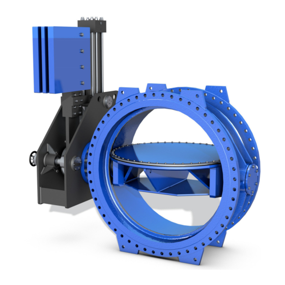
Vag EKN H1200 PS10 Operation Manual (30 pages)
Butterfly valve
Brand:
Vag
| Category:
Control Unit
| Size: 2.25 MB
Table of Contents
Table of Contents
2
Allgemeines
3
Sicherheit
3
General
3
Safety
3
Bestimmungsgemäße Verwendung
4
Kennzeichnung
4
Proper Use
4
Identification
4
Transport Und Lagerung
5
Transport
5
Transport and Storage
5
Bild / Picture 1: Transportlage Auf Dem Flansch / Transport Position on Flange
6
Bild / Picture 2: Transportlage Flanschfüße / Transport Position on Flat Base
6
Lagerung
7
Storage
7
Bild / Picture 3: Aufhängebohrungen VAG EKN® H1200 / Suspension Bores VAG EKN® H1200
7
Bild / Picture 4: Beispiel Lagerung VAG EKN® H1200 Absperrklappe / Example Storage of the VAG EKN® H1200 Butterfly Valve
7
Produktmerkmale
8
Merkmale Und Funktionsbeschreibung
8
Einsatzbereiche
8
Product Features
8
Features and Function Description
8
Applications
8
Leistungsgrenzen
9
Kavitation
9
Performance Limits
9
Cavitation
9
Maximal Zulässige Durchflussgeschwindigkeit
10
Maximum Permissible Flow Velocity
10
Bild / Picture 5: Sigma-Werte Zur Beurteilung Von Kavitation / Evaluation of Cavitation Values
10
Zulässige Und Unzulässige Betriebsweise
11
Sonderausführung Mit Ausbaustück
11
Allgemein
11
Permissible and Impermissible Modes of Operation
11
Special Type with Dismantling Joint
11
General
11
Bild / Picture 6: VAG EKN® H1200 Mit Ausbaustück / VAG EKN® H1200 with Dismantling Joint
11
Montage
12
Wartung
12
Assembly
12
Maintenance
12
Bild / Picture 7: Verstellbarkeit Ausbaustück / Adjustability Dismantling Joint
12
Bild / Picture 8: Ausbaustück / Dismantling Joint
12
Sonderausführung Mit UVV- Verriegelungseinrichtung
13
Special Type with UVV Safety Interlock
13
Bild / Picture 9: Verriegelungseinrichtung / Locking Device
13
Einbau in Die Rohrleitung
14
Anlagenseitige Voraussetzungen
14
Installation into the Pipeline
14
Conditions Required on Site
14
Bild / Picture 10: UVV-Verriegelungseinrichtung / UVV Safety Interlock
14
Bild / Picture 11: UVV-Verriegelungseinrichtung Gesichert Durch Bolzen Und Vorhängeschloss
14
Einbaustelle
15
Einbauten in Der Rohrleitung Vor Und Hinter Der Armatur
15
Installation Location
15
Downstream of the Valve
15
Einbaulage
16
Installation Position
16
Bild / Picture 12: Zulässige Einbaulage / Permissible Installation Position
16
Montagehinweise Und Verbindungselemente
17
Assembly Instructions and Fittings
17
Bild / Picture 13: Unzulässige Einbaulage / Impermissible Installation Position
17
Inbetriebnahme Und Bedienung
19
Visuelle Begutachtung Und Vorbereitung
19
Funktionskontrolle Und Druckprüfung
19
Set up and Operation of the Valve
19
Visual Inspection and Preparation
19
Function Check and Pressure Test
19
Antrieb
20
Allgemeines
20
Armatur Mit VAG Hysec Hydraulischen Fallgewichtsantrieben
20
Actuator
20
General
20
Valves with VAG Hysec Hydraulic Brake and Lift Units
20
Wartung Und Instandhaltung
21
Allgemeine Sicherheitshinweise
21
Maintenance and Repair
21
General Safety Instructions
21
Bild / Picture 14: VAG EKN® H1200 Absperrklappe Mit Hysec Hydraulischer Fallgewichtsantrieb
21
Inspektions- Und Betätigungsintervalle
22
Wartungsarbeiten Und Teilewechsel
22
Konstruktion
22
Empfehlung Für Teilewechsel
22
Reinigung, Schmierung
22
Inspection and Operation Intervals
22
Maintenance Work and Replacement of Parts
22
Design
22
Recommendation for the Replacement of Parts
22
Cleaning and Lubrication
22
Austausch Des Profildichtringes
23
Austausch Der O-Ringe in Der Lagerung
23
Replacement of the Profile Seal
23
Replacement of the O-Ring in the Bearing
23
Bild / Picture 15: Demontage Vom Lagerflansch / Dismantling of Bearing Flange
24
Bild / Picture 16: Demontage Vom Lagerdeckel / Dismantling of Bearing Cover
24
Schraubenanzugsmomente
25
Tightening Torques for Screws
25
Bild / Picture 17: Befestigungsschrauben Für Hydraulischen Fallgewichtsantrieb / Fastening Bolt for Hydraulic Brake and Lift Unit
25
Bild / Picture 18: Haltering Schrauben / Retaining Ring Screws
25
Tabelle / Table 1: Anzugsmomente Für Die Haltering Schrauben / Tightening Torques of Retaining Ring Screws
25
Tabelle / Table 2: Anzugsmomente Für Die Lagerflansch Fixierschrauben / Tightening Torques of Bearing Flange Fixing Screws
25
Störungen, Ursachen Und Abhilfe
26
Trouble Shooting
26
Bild / Picture 19: Lagerflansch Fixierschrauben / Bearing Flange Fixing Screws
26
Bild / Picture 20: Befestigungsschrauben Für Die Hubbremse / Fastening Bolt for Brake and Lift Unit
26
Tabelle / Table 3: Anzugsmomente Für Die Befestigungsschraubenhubbremse / Tightening Torques of Fastening Bolt Brake and Lift Unit
26
Kontakt
30
How to Contact Us
30
Advertisement
Advertisement
Related Products
Vag EKN
VAG EKN H-Series
VAG EKN M-Series
VAG EKN B-Series
Vag EKN AWWA
Vag EROX plus Penstock
Vag EROX plus-O Penstock
Vag Categories
Control Unit
Controller
Firefighting Equipment
Industrial Equipment
More Vag Manuals
Login
Sign In
OR
Sign in with Facebook
Sign in with Google
Upload manual
Upload from disk
Upload from URL