Sign In
Upload
Manuals
Brands
THORLABS Manuals
Controller
ITC510
THORLABS ITC510 Manuals
Manuals and User Guides for THORLABS ITC510. We have
1
THORLABS ITC510 manual available for free PDF download: Operation Manual
THORLABS ITC510 Operation Manual (123 pages)
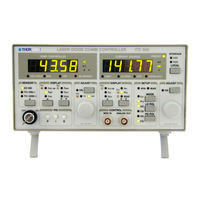
Laser Diode Combi Controller
Brand:
THORLABS
| Category:
Controller
| Size: 1 MB
Table of Contents
Table of Contents
3
1 General Description of the Itc5Xx Controller
9
Packing List
9
Safety
9
Features
12
Mode of Operation
14
Technical Data
15
Technical Data ITC502
15
Technical Data ITC510
18
Operating Elements at the Front Panel
22
Operating Elements at the Rear Panel
23
Pre-Settings
24
Setting the Limit of the Laser Current I
24
Ld Lim
24
Setting the Limit Value of the TEC Current
24
Setting the Temperature Window
24
DIP Switch for "Wake Up" Preset
25
Connecting Components
28
Pin Assignment for the Laser Diode Output
28
Pin Assignment of the TEC Output Jack
30
Connecting a Thermistor
31
Connecting a Temperature Sensor AD590 or AD592
32
Connecting a Temperature Sensor LM135 or LM335
33
Connecting a TEC Element
33
Connecting the Status Indicator
35
Connecting Laser- and Monitor Diode
35
Connecting Interlock and Status LED
37
Temperature Tune Input
38
2 Operating the Itc5Xx
39
Mains Voltage Selector
39
Mains Switch
39
Main Setting Knobs
39
Display
40
Select the Value to be Displayed
41
Operating Mode of the Laser Diode (MODE)
42
Polarity of the Laser Diode (LD POL)
44
Polarity of the Monitor Diode (PD POL)
44
Bias Voltage of the Monitor Diode (BIAS)
44
Adjusting the Bias Voltage of the Monitor Diode
46
Adjusting the Power Display of an Internal Monitor Diode
46
Temperature Window Protection
48
Selecting the Temperature Sensor
48
Polarity Check of the TEC Element
49
Setup and Function of Temperature Controllers
50
Statements and Implications
50
Demands to the Ideal Temperature Control Loop
51
Influences on the Real Temperature Control Loop
51
PID Adjustment
53
Analog Modulation Input
56
Analog Output (I )
57
Laser and TEC Current ON/OFF
58
CP Gain
59
BNC Connector TEMP out
59
BNC Connector Temp Tune
60
Using the Interlock Input
60
Examples of Various Protection Functions
61
Laser Voltage Measurement
62
3 Remote Control by a PC (Itc5Xx-IEEE)
63
IEEE488 Interface
64
Interface Specifications
64
Setting up the Interface
65
Connecting the Instrument
67
IEEE488 Bus Commands
68
Before Programming
70
Nomenclature
70
Program and Response Messages
70
Data Format
71
Common Commands and Queries
73
Identification Query
73
Reset
73
Self-Test Query
73
Set Operation-Complete Bit
73
Operation-Complete Query
74
Wait
74
Event-Status-Enable-Register (ESE)
74
Query Standard-Event-Status-Register (ESR)
74
Service-Request-Enable-Register (SRE)
75
Query Status-Byte-Register (STB)
75
System Command Group
76
Answer Mode
76
Error-LED Mode
76
Querying the Error Queue
77
Averaging Rate
77
Status Command Group
78
Query Device-Error-Condition-Register (DEC)
78
Query Device-Error-Event-Register (DEE)
78
Device-Error-Event-Enable-Register (EDE)
78
Itc5Xx Specific Commands
79
Operation Mode (MODE)
79
Laser Diode Polarity (LDPOL)
79
Photo Diode Polarity (PDPOL)
80
Reading the State of the Temperature Protection (TP)
80
Switching the Bias Voltage on and off (PDBIA)
81
Turn the Output on and off (LASER)
82
Reading the Laser Diode Hardware Limit (LIMCP)
83
Laser Diode Current (ILD)
83
Monitor Diode Current (IMD)
84
Calibrating a Photo Diode (CALPD)
85
Optical Power (POPT)
86
Reading the Optical Power from the Display (POPTP)
87
Reading the Laser Diode Voltage (VLD)
87
Reading the Bias Voltage (VBIAS)
87
Temperature Sensor (SENS)
88
Switching the TEC on and off (TEC)
88
Temperature (Only AD590) (TEMP)
89
Resistance of the Thermistor (RESI)
90
Reading the TEC Current Hardware Limit (LIMTP)
91
Reading the TEC Current (ITE)
91
Reading the Temperature/Resistance Window (WIN)
91
Reading the TEC Voltage (VTE)
91
Error Messages of the Itc5Xx
92
General Errors
92
Itc5Xx Operation Error Messages
95
Status Reporting
98
Standard Event Status Register (ESR)
98
Standard Event Status Enable Register (ESE)
101
Status Byte Register (STB)
101
Service Request Enable Register (SRE)
102
Reading the STB by Detecting SRQ
102
Reading the STB by *STB? Command
102
Reading the STB by Serial Poll
102
Device Error Condition Register (DEC)
103
Device Error Event Register (DEE)
104
Device Error Event Enable Register (EDE)
104
Hints for Setting up Control Programs
105
4 Maintenance
108
Repair
108
Cleaning
108
Selecting the Line Voltage
108
Exchanging the Line Fuse
109
Trouble-Shooting
111
5 Service
114
Exchange of Internal Fuses
114
6 Appendix
115
Warranty
115
Certifications and Compliances
116
Thorlabs "End of Life" Policy (WEEE)
117
Waste Treatment on Your Own Responsibility
118
Ecological Background
118
List of Acronyms
119
List of Figures
121
7 Addresses
122
Advertisement
Advertisement
Related Products
THORLABS ITC502
Thorlabs ITC1 Series
Thorlabs ITC133
Thorlabs ITC100P
THORLABS ITC4000 Series
THORLABS ITC4001
THORLABS ITC4005
THORLABS ITC4005QCL
Thorlabs ITC100F
Thorlabs ITC110
THORLABS Categories
Measuring Instruments
Controller
Laboratory Equipment
Security Sensors
Industrial Equipment
More THORLABS Manuals
Login
Sign In
OR
Sign in with Facebook
Sign in with Google
Upload manual
Upload from disk
Upload from URL