Sign In
Upload
Manuals
Brands
State Water Heaters Manuals
Water Heater
SUF-100-250
State Water Heaters SUF-100-250 Manuals
Manuals and User Guides for State Water Heaters SUF-100-250. We have
6
State Water Heaters SUF-100-250 manuals available for free PDF download: Installation, User And Service Manual, Instruction Manual, Service Handbook
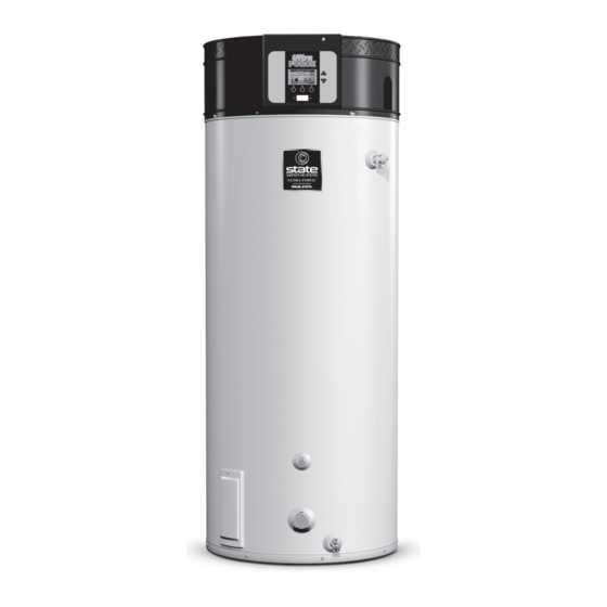
State Water Heaters SUF-100-250 Installation, User And Service Manual (118 pages)
Brand:
State Water Heaters
| Category:
Water Heater
| Size: 4.67 MB
Table of Contents
Preface
3
Copyright
3
Trademarks
3
Warranty
3
Liability
3
Compliance
4
Regulations
4
Contact Information
5
About this Manual
7
Scope
7
Target Group
7
Notation Conventions
7
Document Identification
8
Table of Contents
9
User Part
13
Introduction
15
Safety
17
Interface
19
Operator Interface
19
Explanation of Icons
19
Control Switch
20
Buttons
20
PC Connection
20
Status of the Water Heater
21
Operating Modes
21
Error Conditions
22
Service Conditions
23
Anode Warning
23
Use
25
Turn on the Water Heater
25
The Appliance's Heating Cycle
25
Turn off the Water Heater
27
Turn off for a Short Period
27
Isolate from the Mains
28
Turn off for a Long Period
28
Main Menu
29
Notation Conventions for Menu-Related Instructions
29
Switching to on Mode
30
Setting the Water Temperature
30
Week Program
30
Starting and Stopping the Week Program
31
Changing the Appliance's Standard Week Program
31
Adding Times to a Week Program
34
Deleting Times from a Week Program
35
Extra Period
36
Settings
38
Installation, Maintenance and Service Part
41
Introduction
43
About the Water Heater
43
The Appliance's Heating Cycle
43
Working Principle
43
Operating Cycle
45
Safety
47
Safety Instructions
47
Instructions on the Water Heater
48
Safety Devices
49
Protection for the Water Heater
49
Safety of the Installation
50
Environmental Aspects
50
Recycling
50
Disposal
51
Installation
53
Packaging
53
Conditions
53
Ambient Conditions
53
Maximum Floor Load
53
Water Composition
54
Working Clearances
54
Installation Diagram
55
Water Connections
56
Unvented Water Connections
56
Vented Water Connections
57
Gas Connection
58
Venting System
58
C13/C33 Concentric Systems
60
C13/C33 Parallel Systems
62
C43/C53/C63 Systems
64
Electrical Connections
65
Preparation
65
Mains Power
66
Optional Electrical Connections
66
Commissioning
67
Filling
67
Procedure for Checking the Supply Pressure
68
Procedure for Checking the Gas Control Valve Pressure
70
CO 2 Adjustment
71
Switching Pressure Measurement
74
Turn on the Water Heater
74
Decommisioning
74
Turn off the Water Heater
74
Draining
74
Conversion of Gas Type
77
Settings
79
Operator Interface
79
Service Program
79
Hysteresis
79
Display the Error History
80
Display the Water Heater History
80
Display the Selected Water Heater
81
Switch the Pump on or off
81
Setting the Service Interval
81
Service Mode
82
Setting Legionella Prevention
82
Setting the Central Heating Configuration
83
Maintenance
85
Preparation
85
Water-Side Maintenance
86
Descale the Tank
86
Clean the Condensate Drain
87
Gas-Side Maintenance
87
Clean the Burner
87
Clean the Heat Exchanger
87
Finalization
88
Troubleshooting
89
Errors and Warnings
89
General Errors
90
Displayed Errors
91
Warnings
96
Appendices
97
Technical Details
97
Dimensions
101
Gas Details
105
Week Program Card
107
Electrical Wiring Diagram
109
Menu Structure
111
Declaration of Conformity
112
Warranty
113
Index
115
Advertisement
State Water Heaters SUF-100-250 Instruction Manual (80 pages)
commercial gas water heaters
Brand:
State Water Heaters
| Category:
Water Heater
| Size: 15.53 MB
Table of Contents
Instruction Manual
1
Table of Contents
2
SAFE Installation, USE and Service
3
General Safety Information
4
Precautions
4
Icomm™ & Bacnet Compatible
6
Introduction
6
Preparing for the Installation
6
Qualifications
6
Basic Operation
7
Features and Components
7
Top Views
8
Side Views
10
11
Installation Considerations
11
Rough in Dimensions
11
Recovery Capacities
12
Locating the Water Heater
12
Clearance to Combustible Materials
13
Service Clearance
13
Insulation Blankets
13
Installation Requirements
14
Gas Pressure Requirements
14
Supply Gas Line
14
Supply Gas Regulator
14
Power Supply
14
Mixing Valves
15
Dishwashing Machines
15
Closed Water Systems
15
Thermal Expansion
15
Temperature-Pressure Relief Valve
16
Condensate Drain
17
Air Requirements
18
Fresh Air Openings for Confined Spaces
19
Outdoor Air through Two Openings
19
Outdoor Air through Two Horizontal Ducts
19
Outdoor Air through One Opening
19
Outdoor Air through Two Vertical Ducts
20
Air from Other Indoor Spaces
20
Commonwealth of Massachusetts
21
VENTING Installation
22
General Venting Information
22
Category IV Appliance
22
Power Vent Configuration
22
Direct Vent Configuration
22
General Venting Instructions
22
Venting Requirements
24
Maximum Equivalent Lengths
24
Minimum Equivalent Lengths
24
Maximum Number of Elbows
24
Venting Installation Sequence
25
Power Vent Installation
25
Direct Vent Installation
25
Intake Air Connection
26
Intake Air Screen
26
Vertical Termination Installation
27
Sidewall Termination Installation
29
Concentric Termination Installation
30
Inch Concentric Termination Installation
31
Multiple Concentric Termination Clearances
32
Multiple Concentric Termination Arrangements
33
Venting Arrangements
34
Termination Clearances Sidewall Power Vent
36
Termination Clearances Sidewall Direct Vent
37
WATER HEATER Installation
38
Condensate Drain Installation
38
Supply Gas Line Installation
39
Supply Gas Regulator Installation
40
Electrical Wiring
41
Power Supply Connections
41
Enable/Disable Circuit
41
Water Line Connections
42
T&P Valve Discharge Pipe
42
Temperature Regulation
43
High Temperature Limit Control (ECO)
43
Thermostat Control
43
Control System Operation
44
Control System Navigation
44
The Desktop Screen
44
Status Icons
45
Operating States
46
Control System Menus
46
User Settings & Control System Menus
47
Temperatures Menu
47
Heater Status Menu
48
Display Settings
49
Heater Information
49
Current Fault
50
Fault History
50
Fault Occurrence
50
Restore Factory Defaults
50
Service Contact Information
51
Start up
52
Initial Start up
52
Lighting the Water Heater
53
Supply Gas Pressure Adjustment
54
Manifold Gas Pressure Adjustment
54
Checking the Firing Rate
55
High Altitude Installations
55
Lighting the Water Heater
56
Lighting & Operation Labels
56
For Your Safety Read before Operating
57
Operating Instructions
57
To Turn off Gas to Appliance
57
Troubleshooting
58
Installation Checklist
58
Sequence of Operation
58
Sequence of Operation Flow Chart
59
Operational Problems
60
Rough Starting, Rough Operation
60
Momentary Ignition
60
Not Enough or no Hot Water
60
Alert Conditions
61
Diagnostic Checks
61
Fault and Alert Conditions
61
Fault Conditions
61
Resetting Control System Lock Outs
61
Fault and Alert Messages
62
Blocked Air Intake
63
Blower Prover Open
63
Maintenance
64
Maintenance Schedule
64
Lime Scale Removal
65
Sediment Removal
65
Drain Valve and Access Panels
66
Powered Anode Rods
66
Vent System
66
67
Diagrams
67
CCB - Central Control Board Layout
67
SUF 120 & 150 Wiring Diagram
68
SUF 199 & 250 Wiring Diagram
69
Circulation Pump Wiring Diagrams
70
Water Piping Diagrams
71
Limited Warranty
78
State Water Heaters SUF-100-250 Installation, User And Service Manual (97 pages)
Brand:
State Water Heaters
| Category:
Water Heater
| Size: 2.82 MB
Table of Contents
Table of Contents
5
About the Appliance
9
What to Do if You Smell Gas
9
Target Groups
10
Maintenance
10
Forms of Notatins
11
Overview of the Document
11
Working Principle of the Appliance
13
Product View and Parts Identification
13
The Appliance's Heating Cycle
14
Protection for the Appliance
14
Water Temperature Protection
14
Gas Valve
15
Fan
15
Pressure Switch
15
Safety of the Installation
16
Unvented Installation
16
Vented Installation
16
T&P Valve
16
Installation
17
Environmental Conditions
17
Humidity and Ambient Temperature
18
Maximum Floor Loading
18
Water Composition
18
Working Clearances
18
Technical Specifications
19
Dimensions of the Appliance
20
Installation Diagram
23
Water Connections, Unvented
24
Cold/Hot Water Side
24
Circulation Pipe
24
Condensation Drainage
24
Water Connections, Vented
25
Gas Connection
25
Air Supply and Flue
26
Requirements for Flue Gas Discharge Materials
26
Concentric Connections
28
Explanation of Installation Types
28
Concentric Wall Flue Terminal Specifications
29
Concentric Roof Flue Terminal Specifications
30
Parallel Connections
31
Electrical Connection
32
Terminal Block
33
Connecting Mains Power
34
Isolating Transformer
34
Checking the Supply Pressure and Burner Pressure
35
Connecting Continuous Pump/Program-Controlled Pump
35
Connecting an Extra on Mode Switch ("Tank On")
35
Connecting an Extra Error Signal ('Alarm On')
35
Pressure Check Procedure
36
Adjusting Pressure
38
Finilizing
38
Conversion to a Different Gas Category
39
Filling
43
Filling Unvented Installations
44
Filling Vented Installations
44
Draining
45
Draining Unvented Installations
46
Draining Vented Installations
46
The Control Panel
49
Explanation of Symbols
49
Electronic Controlled On/Off Switch
49
Navigation Buttons
50
PC Connection
50
Status of the Appliance
51
Operating Modes
51
Error Conditions
52
Service Condition
52
Prog Mode
52
Starting and Running
53
Shutting down for a Brief Period ("Off Mode")
55
Electrically Isolating the Appliance
55
Shutting the Appliance down for a Longer Period
55
Main Menu
57
Notational Convention for Menu-Related Instructions
57
Switching into "On Mode"
57
Setting the Water Temperature
57
Week Program
58
Starting and Stopping the Week Program
58
Changing the Appliance's Standard Week Program
58
Week Program: Setting the Switch-On Time
59
Week Program: Setting Switch-Off Time
59
Week Program: Adding Times
60
Week Program: Setting the Water Temperature
60
Week Program: Setting Program-Controlled Pump
60
Week Program: Deleting Times
61
Extra Period Programming
62
Settings
63
Setting Menu Language
63
Setting Day and Time
63
Setting Program-Controlled Pump
63
Displaying Appliance Specifications
64
Service Program
65
Setting the Hysteresis
65
Displaying the Error History
65
Displaying the Appliance History
66
Display the Selected Appliance
66
Setting the Pump On/Off
66
Setting the Service Interval
66
Troubleshooting
67
Maintenance Frequency
79
Determining Service Interval
79
Preparation for Maintenance
81
Water-Side Maintenance
83
Anode Inspection
83
Descaling and Cleaning the Tank
83
Gas-Side Maintenance
84
Cleaning the Burner/Orifice/Heat Exchanger
84
Electrical Diagram
90
Instruction Manual
90
Index
95
Advertisement
State Water Heaters SUF-100-250 Instruction Manual (80 pages)
SERIES 300 & 301
Brand:
State Water Heaters
| Category:
Water Heater
| Size: 14.68 MB
Table of Contents
For Your Safety
1
Instruction Manual
1
Table of Contents
2
General Safety Information
4
Precautions
4
Grounding Instructions
4
Hydrogen Gas Flammable
4
Introduction
6
Abbreviations Used
6
Qualifications
6
ICOMM and BMS/EMS COMPATIBILITY
6
Preparing for the Installation
6
Basic Operation
7
Modulation
7
Blower/Burner Assembly Detail
7
Features and Components
7
Components- Top View (All Models)
8
Side Views
9
Installation Considerations
10
Rough-In Dimensions
10
Locating the Water Heater
11
Optional Direct Vent Terminations
12
Hard Water
12
Circulation Pumps
12
Insulation Blankets
12
Installation Requirements
13
Gas Supply Systems
13
Supply Gas Regulator
13
Power Supply
13
Mixing Valves
14
Dish-Washing Machines
14
Closed Water Systems
14
Thermal Expansion
14
Temperature-Pressure Relief Valve
15
Condensate Drain
16
Combustible Material Storage
16
Contaminated Air
16
Air Requirements
17
Fresh Air Openings for Confined Spaces
18
Installation Requirements - Commonwealth of Massachusetts
20
Venting Installation
21
General Venting Information
21
Category IV Appliances
21
General Venting Instructions
21
Venting Requirements
22
Common Direct Venting
23
Venting Installation Sequence
23
Power Vent Installation
23
Direct Vent Installation
24
Vertical Termination Installation
25
Sidewall Termination Installation
27
Polypropylene Installations
28
AL29-4C ® Vent Installations
29
Common Direct Venting Requirements
29
Concentric Termination Installation Preparation
30
Concentric Termination Installation
31
Low-Profile Vent Termination Installation
34
Venting Arrangements
35
Venting Arrangements
36
Termination Clearances Sidewall Power Vent
37
Termination Clearances Sidewall Direct Vent
38
Water Heater Installation
39
Condensate Drain Installation
39
Supply Gas Line Installation
40
Gas Line Leak Testing
41
Electrical Wiring
41
Water Line Connections
43
T&P Valve Discharge Pipe
43
Temperature Regulation
44
High Temperature Limit Control (ECO)
44
Thermostat Control
44
Firing Rate Modulation
44
High Temperature Applications
44
Control System Operation
45
Control System Navigation
45
User Settings & Control System Menus
48
Start up
53
Prior to Start up
53
Initial Start up
53
Lighting Operation & Labels
54
Checking the Firing Rate
56
High Altitude Installations
56
Troubleshooting
57
Installation Checklist
57
Sequence of Operation
57
Sequence of Operation Flow Chart
58
Operational Problems
59
Fault and Alert Conditions
60
Ignition Failure
61
Blocked Air Intake
61
Maintenance
63
General
63
Draining and Flushing
63
Sediment Removal
64
Powered Anode Rods
64
Drain Valve and Access Panels
64
Temperature-Pressure Relief Valve Test
64
Vent System
65
Diagrams
66
Central Control Board (CCB) Layout
66
Wiring Diagram
67
Circulation Pump Wiring Diagrams
68
Water Piping Diagrams
69
Notes
77
State Water Heaters SUF-100-250 Instruction Manual (80 pages)
Brand:
State Water Heaters
| Category:
Water Heater
| Size: 14.71 MB
Table of Contents
Table of Contents
2
General Safety Information
4
Precautions
4
Grounding Instructions
4
Hydrogen Gas Flammable
4
Introduction
6
Abbreviations Used
6
Qualifications
6
ICOMM and BMS/EMS COMPATIBILITY
6
Preparing for the Installation
6
Basic Operation
7
Modulation
7
Blower/Burner Assembly Detail
7
Features and Components
7
Components- Top View (All Models)
8
Side Views
9
Installation Considerations
10
Rough-In Dimensions
10
Locating the Water Heater
11
Optional Direct Vent Terminations
12
Hard Water
12
Circulation Pumps
12
Insulation Blankets
12
Installation Requirements
13
Gas Supply Systems
13
Supply Gas Regulator
13
Power Supply
13
Mixing Valves
14
Dish-Washing Machines
14
Closed Water Systems
14
Thermal Expansion
14
Temperature-Pressure Relief Valve
15
Condensate Drain
16
Combustible Material Storage
16
Contaminated Air
16
Air Requirements
17
Fresh Air Openings for Confined Spaces
18
Installation Requirements - Commonwealth of Massachusetts
20
Venting Installation
21
General Venting Information
21
Category IV Appliances
21
General Venting Instructions
21
Venting Requirements
22
Common Direct Venting
23
Venting Installation Sequence
23
Power Vent Installation
23
Direct Vent Installation
24
Vertical Termination Installation
25
Sidewall Termination Installation
27
Polypropylene Installations
28
AL29-4C ® Vent Installations
29
Common Direct Venting Requirements
29
Concentric Termination Installation Preparation
30
Concentric Termination Installation
31
Low-Profile Vent Termination Installation
34
Venting Arrangements
35
Venting Arrangements
36
Termination Clearances Sidewall Power Vent
37
Termination Clearances Sidewall Direct Vent
38
Water Heater Installation
39
Condensate Drain Installation
39
Supply Gas Line Installation
40
Gas Line Leak Testing
41
Electrical Wiring
41
Water Line Connections
43
T&P Valve Discharge Pipe
43
Temperature Regulation
44
High Temperature Limit Control (ECO)
44
Thermostat Control
44
Firing Rate Modulation
44
High Temperature Applications
44
Control System Operation
45
Control System Navigation
45
User Settings & Control System Menus
48
Start up
53
Prior to Start up
53
Initial Start up
53
Lighting Operation & Labels
54
Checking the Firing Rate
56
High Altitude Installations
56
Troubleshooting
57
Installation Checklist
57
Sequence of Operation
57
Sequence of Operation Flow Chart
58
Operational Problems
59
Fault and Alert Conditions
60
Maintenance
63
General
63
Draining and Flushing
63
Sediment Removal
64
Powered Anode Rods
64
Drain Valve and Access Panels
64
Temperature-Pressure Relief Valve Test
64
Vent System
65
Diagrams
66
Central Control Board (CCB) Layout
66
Wiring Diagram
67
Circulation Pump Wiring Diagrams
68
Water Piping Diagrams
69
Notes
77
State Water Heaters SUF-100-250 Service Handbook (54 pages)
COMMERCIAL GAS HIGH EFFICIENCY WATER HEATERS
Brand:
State Water Heaters
| Category:
Water Heater
| Size: 7.03 MB
Table of Contents
Table of Contents
2
Introduction
3
Qualifications
3
Service Warning
3
Service Reminder
3
Tools Recommended
3
Installation Considerations
4
Instruction Manual
4
Closed Water Systems
4
Thermal Expansion
4
Air Requirements
4
Contaminated Air
4
Features and Components
5
Combustion Blower & Burner Assembly
5
Top View: SUF 60120 - 100250 Models
6
Top View: SUF 119300 - 119500 Models
6
Sequence of Operation Flow Chart
7
Fault and Alert Codes
8
Low Gas Pressure
8
High Altitude
8
Gas Pressure Specifications
8
Gas Supply Systems
9
Supply Gas Regulator
9
Gas Pressure Test
10
Pressure Switches
12
Control System Monitoring
12
Pressure Switch Tests
13
Continuity Test During Standby
13
Continuity Test During Operation
14
Pressure Test During Operation
14
Pressure Switch Settings
15
Ignition Failure
16
Blocked Air Intake
19
Blocked Exhaust
20
Flame Sensor Error
21
Gas Control Valve
21
Gas Control Valve Voltage Tests
22
Flame Sensor
23
Flame Sensing Operation
23
Flame Sensing Current Test
24
No Water
25
Powered Anodes
25
Power Anode Cleaning and Removal
25
Anode Shorted
27
Temperature Probe Short (Upper or Lower)
28
Temperature Probe
28
Temperature Sensor Test
29
ECO Continuity Test
29
Temperature Probe Open (Upper or Lower)
31
Venting
32
General Venting Information
32
Intake Air Connection
33
Electrical Connections - All Models
34
Electrical Wiring
34
Power Supply Connections
34
Enable/ Disable Switch
35
Power Supply Test
35
Installation Check List
36
Operation and Service
37
How It Works
37
Combustion Blower
37
Modulation
37
Condensate Prevention Algorithm
37
Blower Speed Control
39
Burner Assembly
40
Combustion Blower and Burner Removal/ Installation Instructions
41
Spark Igniter
42
Gas Orifice - Suf 119300 - 119500 Models
44
Orifice Chart - SUF 119300 - 119500 Models
44
Ccb (Central Control Board)
45
CCB Cover Removal and Replacement
46
CCB Circuit Board Layout
47
CCB Connection Identification
48
Wiring Diagram - Suf 60120 - 119500
50
Control Overview
51
Icomm
52
Notes
53
Advertisement
Related Products
State Water Heaters Ultra Forcce SUF 100 240
State Water Heaters SUF 100 250
State Water Heaters Utra-Force SUF100 240NE
State Water Heaters SUF 100-150
State Water Heaters SUF 100-199
State Water Heaters SUF 100
State Water Heaters SUF 100 THRU 250
State Water Heaters SUF 100 150
State Water Heaters SUF 100 199
State Water Heaters Utra-Force SUF100 150NE
State Water Heaters Categories
Water Heater
Heat Pump
Boiler
Pest Control
Gas water heater
More State Water Heaters Manuals
Login
Sign In
OR
Sign in with Facebook
Sign in with Google
Upload manual
Upload from disk
Upload from URL