
Related Manuals for State Water Heaters SUF 120-300


Summary of Contents for State Water Heaters SUF 120-300
- Page 1 60-120 100-150 100-199 100-250 120-300 120-400 120-500 Installation Installation Installation Installation User and User and User and User and Service Manual Service Manual Service Manual Service Manual...
- Page 2 your installer...
-
Page 3: Preface
STATE Water Heaters. STATE Water Heaters reserves the right to modify specifications in this manual. Trademarks Brand names in this manual are registered trademarks of their respective owners. -
Page 4: Compliance
Compliance To safely produce domestic hot water, the design and construction of the SUF water heaters is in accordance with: • the European Gas Appliance Directive (GAD). • the European Standard for Gas–fired storage water heaters for the production of domestic hot water (EN89). -
Page 5: Contact Information
Institute of Gas Engineers and Managers (IGEM) Publications • IGE/UP/1: Soundness testing and purging of industrial and commercial gas installations. • IGE/UP/1A: Soundness testing and direct purging of small low pressure industrial and commercial natural gas installations. • IGE/UP/2: Gas installation pipework, boosters and compressors on industrial and commercial premises. -
Page 7: About This Manual
About this manual Scope This manual gives information about safe and correct use of the water heater and how installation, maintenance and service activities have to be done correctly. You must obey the instructions in this manual. Caution Read this manual carefully before you start the water heater. It can cause personal injury and damage to the water heater when you do not read the manual and/or do not obey the instructions. -
Page 8: Document Identification
This manual contains the following text styles/symbols for situations that may endanger users/engineers, cause damage to equipment or need special attention: Note A note gives more information on a topic. Caution Obey the caution instructions to prevent damage of the water heater. Warning Obey the warning instructions to prevent danger of personal injury, and serious damage to the water heater. -
Page 9: Table Of Contents
Table of Contents Preface..................3 Copyright................3 Trademarks............... 3 Warranty................3 Liability................3 Compliance............... 4 Regulations............... 4 Contact information............5 About this manual............... 7 Scope................7 Target group..............7 Notation conventions............7 Document identification............8 User part..............13 Introduction................15 Safety..................17 Interface................... 19 Operator interface............ - Page 10 4.1.1 The appliance's heating cycle..........25 Turn off the water heater...........27 4.2.1 Turn off for a short period..........27 4.2.2 Isolate from the mains............28 4.2.3 Turn off for a long period........... 28 Main menu..............29 4.3.1 Notation conventions for menu-related instructions....29 4.3.2 Switching to ON mode............30 4.3.3...
- Page 11 7.2.4 Working clearances............54 Installation diagram............55 Water connections............56 7.4.1 Unvented water connections..........56 7.4.2 Vented water connections..........57 Gas connection..............58 Venting system..............58 7.6.1 C13/C33 concentric systems..........60 7.6.2 C13/C33 parallel systems..........62 7.6.3 C43/C53/C63 systems............64 Electrical connections............65 7.7.1 Preparation..............65 7.7.2...
- Page 12 10.1 Preparation..............85 10.2 Water-side maintenance............ 86 10.2.1 Descale the tank.............. 86 10.2.2 Clean the condensate drain..........87 10.3 Gas-side maintenance............87 10.3.1 Clean the burner.............. 87 10.3.2 Clean the heat exchanger..........87 10.4 Finalization..............88 Troubleshooting................ 89 11.1 Errors and warnings............89 11.1.1 General errors..............90 11.1.2 Displayed errors...............
-
Page 13: User Part
User part 0311720_SUF_120-500_III_UKUK_V2.0 , 2017-08-01... -
Page 15: Introduction
Introduction The SUF water heater stores and heats water for sanitary purposes. Cold water enters the bottom of the tank through the water inlet (1). The heated water leaves the tank at the top through the hot water outlet (2). To operate the water heater, the operator interface (3) and control switch (4) are used. - Page 16 User part...
-
Page 17: Safety
Safety STATE cannot be held responsible for damages or injuries leading back to: • Failure to follow the instructions provided in this manual. • Carelessness during use or maintenance of the water heater. Every user has to study the user part of this manual and has to follow the instructions in this part of the manual strictly. - Page 18 User part...
-
Page 19: Interface
Interface Operator interface The operator interface is completely menu-driven, and comprises: • a 4-line display with 20 characters per line; • 6 buttons for controlling the water heater (below the display); • 6 graphical symbols (above the display); • a connector for a service PC; •... -
Page 20: Control Switch
Control switch The control switch of the controller turns the water heater ON and OFF. Note that in the OFF position the water heater remains electrically live, in order for the continuous pump to stay running. After switching on, the text INTERNAL CHECK appears on the display for about 10 seconds. -
Page 21: Status Of The Water Heater
Status of the water heater During operation, the display shows the status of the water heater. 3.6.1 Operating modes When running, the water heater has four basic operating modes, namely: • OFF (see section 3.6.1.1) • ON (see section 3.6.1.2) •... -
Page 22: Error Conditions
3.6.1.4 PROG In this mode a preset week program is active, and the water heater responds continually to demand within the time periods set in the week program. There are two distinct situations possible in this mode: The current time falls within a set time period of the week program. The figure shows the display with the following information: line one: the text PROG;... -
Page 23: Service Conditions
3.6.3 Service conditions The figure shows the message SERVICE REQUIRED. If this message appears, the water heater needs a service and maintenance inspection. In this case, contact your service and maintenance engineer. Note Regular maintenance extends the service life of the water heater. Note The message SERVICE REQUIRED is based on the number of expired burning hours and the preset service interval. - Page 24 User part...
-
Page 25: Use
Turn on the water heater Start the water heater as follows: Fill the water heater (see section 7.8.1). Open the manual gas valve. Switch on the power to the water heater using the isolator between the water heater and the power supply. Switch the controller ON by setting the control switch to position I. - Page 26 When the water heater starts, it will run through the following steps: The water temperature drops below the set temperature of (for example) 65°C. The controller detects a heat demand and starts the operating cycle. The icon is activated. The message HEAT DEMAND appears. Once demand is registered, the fan is started to vent any gases that may be present.
-
Page 27: Turn Off The Water Heater
When the water is up to temperature, the heat demand ceases and the post-purge starts. This takes about 25 seconds. The icons are dimmed. The icon is activated. The message POST PURGE appears. Following the post-purge, the fan stops and the pressure switch opens: The icons are dimmed. -
Page 28: Isolate From The Mains
4.2.2 Isolate from the mains The water heater may only be isolated from mains power in the correct way. The correct procedure is as follows: Activate the MENU with [ Position the cursor in front of OFF. Confirm OFF with [ENTER]. Caution Failure to wait until the fan stops can cause damage to the water heater. -
Page 29: Main Menu
Main menu The MENU is reached by pressing [ ] on the operator interface. The main menu comprises: • Select this option if you wish to turn off the water heater for a short period (see section 4.2), but do not wish to drain it. In this mode, the frost protection is active. This prevents water from freezing in the water heater. -
Page 30: Switching To On Mode
4.3.2 Switching to ON mode You can switch the water heater to ON mode from any operational mode, as follows: ]: ON | START OPERATION Confirm with [ENTER]. Note Also refer to the chapter on starting the water heater (see section 4.1). 4.3.3 Setting the water temperature 4.3.3.1... -
Page 31: Starting And Stopping The Week Program
day of the week and the temperature. The third line shows the next switching time of the week program and the programmed temperature. The fourth line shows the text PROGRAM ACTIVATED. The appliance's default week program switches the appliance on every day at 00:00 and off at 23:59. - Page 32 The display shows the menu for the week program, see the figure below. With the default setting, the program switches on and off every day at 00:00 and 23:59 respectively, the water temperature is 65ºC and the pump is switched on (P). Example As an example, we will set the switch-on time for Sunday to 08:15 hours, and the matching switch-off time to 12:45 hours.
- Page 33 Use [ ] and [ ] to set the minutes. In the example, this is 15. Confirm with [ENTER]. The cursor moves to the switch-off hour digits, which will blink. 4.3.6.2 Week program: setting the switch-off time Use [ ] and [ ] to set the hours. In the example, this is 12. Confirm with [ENTER].
-
Page 34: Adding Times To A Week Program
After changing all desired switch-on and switch off times, you can start running the week program: Scroll with [ ] to START OPERATION. Confirm with [ENTER]. 4.3.7 Adding times to a week program Call up the menu to INSERT switch-on and switch-off times into a week program as follows: ]: WEEK PROGRAM | PROGRAM OVERVIEW. -
Page 35: Deleting Times From A Week Program
4.3.8 Deleting times from a week program All switch-on/off times are shown sequentially in the display. Assume that the switch- on/off times for the water heater are programmed as in the figure. To delete a period, proceed as follows: ]: WEEK PROGRAM | PROGRAM OVERVIEW. Confirm with [ENTER]. -
Page 36: Extra Period
The lines showing switch-on/off times are replaced by the text DELETE BLOCK?. See the figure. Confirm with [ENTER]. (or use [RESET] to cancel). The switching period has been deleted. You will return now to the week program menu. The cursor points to the first programmed period. Scroll with [ ] to START OPERATION. - Page 37 Setting the switch-on time Use [ ] and [ ] to set the day. In the example this is SU. Confirm with [ENTER]. The cursor moves to the hour digits, which will blink. Use [ ] and [ ] to set the switch-on hour to the desired value. In the example, this is 08.
-
Page 38: Settings
Setting the program-controlled pump If required, a pump can be controlled during the period. Use [ ] and [ ] to set PUMP ON. The pump ensures a regular circulation of hot water in the hot water pipes. You can skip this step if you there is no pump in your hot water circuit. Confirm with [ENTER]. - Page 39 The language is set. 4.3.10.2 Setting day and time To enter the time and day: Call up the menu for entering the day and time as follows: ]: SETTINGS. Confirm with [ENTER]. The display shows the menu for settings. Scroll with [ ] and [ ] to DAY/TIME. Confirm with [ENTER].
- Page 40 4.3.10.3 Displaying water heater specifications Note This category is solely intended for the installation engineer and/or service and maintenance engineer. The corrected data is shown in the table of general and electrical data (see section 12.1). Call up the menu to display the water heater specifications as follows: ]: SETTINGS.
-
Page 41: Installation, Maintenance And Service Part
Installation, Maintenance and Service part 0311720_SUF_120-500_III_UKUK_V2.0 , 2017-08-01... - Page 42 User part...
-
Page 43: Introduction
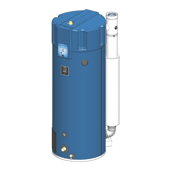
Introduction About the water heater The SUF water heater is intended for heating water for sanitary purposes. The SUF is a condensing gas–fired storage water heater with a fan in the air intake. The flue gasses transfer their heat to the water through an efficient heat exchanger. The water heater has a concentric venting connector and can function as an open or as a room- sealed water heater. - Page 44 Temperature sensor T Cold water inlet Drain valve Gas control valve Burner Air supply hose Hot surface igniter Flame probe Fig. Water heater SUF 120-300, 120-400, 120-500 Chimney pipe Condens trap Insulation layer Potentiostat Base Venturi Flue gas test point...
-
Page 45: Operating Cycle
Operating cycle The temperature sensor T (7) measures the water temperature at the top of the water heater (T ). This temperature is sent to the controller. As soon as T is lower than the set water temperature (T ), the controller registers a "heat demand". The fan (18) starts running and the gas control valve (16) is opened. - Page 46 Installation, Maintenance and Service part...
-
Page 47: Safety
Safety Safety instructions For safety instructions about the use of the water heater, refer to Safety (see section 2) in the User part of this manual. Warning Installation, maintenance and service must be carried out by a qualified engineer in compliance with the general and local regulations imposed by the gas, water and power supply companies and the fire brigade. -
Page 48: Instructions On The Water Heater
Caution The anode protection remains active when the water heater is in OFF mode and the control switch is set to 0. Note Any leakage from the tank and/or connections can cause damage to the immediate environment or floors below the level of the boiler room. Install the water heater above a waste water drain or in a suitable metal leak tray. -
Page 49: Safety Devices
Safety devices 6.3.1 Protection for the water heater 6.3.1.1 Water temperature protection Using temperature sensors T (7) and T (13), the controller monitors three temperatures that are important for safety. The table explains the functioning of the temperature sensors. Safety Description Anti-frost The frost protection cuts in. -
Page 50: Safety Of The Installation
6.3.2 Safety of the installation Excessive pressure in the tank can damage the enamelled layer (in the water heater) or the tank itself. An inlet combination and pressure-reducing valve prevents this. The inlet combination acts as a stop valve, non-return valve and overflow valve. If the water mains pressure is too high, a pressure-reducing valve must be used (Refer to the general and electric specifications in the appendices (see section 12)). -
Page 51: Disposal
6.4.2 Disposal Old end-of-life appliances contain materials that need to be recycled. When you discard devices at the end of their service life, you must obey local legislation related to waste disposal. Never discard your old device together with regular waste. Put the device into a municipal waste collection depot for electrical and electronic equipment. - Page 52 Installation, Maintenance and Service part...
-
Page 53: Installation
Installation Warning The installation must be done by a qualified person, in compliance with general and local applicable regulations. Caution The water heater may not be used in rooms where chemical substances are stored or used because of the risk of explosion and corrosion of the water heater. Some propellants, bleaching agents and degreasing agents etc. -
Page 54: Water Composition
Fig. Working clearances Fig. Working clearances SUF 60-120 - 100-250 SUF 120-300 - 120-500 Note When installing the water heater, be aware that any leakage from the tank and/or connections can cause damage to the immediate environment or floors below the level of the boiler room. -
Page 55: Installation Diagram
Installation diagram Fig. Installation diagram Pressure reducing U N V E N T E D valve (mandatory if the mains water pressure is too high) T&P valve Stop valve (recommended) Non-return valve (mandatory) Circulation pump (optional) Drain valve Manual gas valve (mandatory) Service stop valve Temperature gauge... -
Page 56: Water Connections
Note Use this installation diagram when you: • install the water connections (see section 7.4) • install the condensate drain (see section 7.4.1.4) • install the gas connection (see section 7.5) • fill the water heater (see section 7.8.1) • drain the water heater (see section 7.9.2) Water connections 7.4.1... -
Page 57: Vented Water Connections
7.4.1.4 Condensation drain Fit a sloping waste water pipe to the condens trap (13) for condensation drainage and connect this via an open connection to the waste water discharge. Caution If the condensation drain is not fitted to the waste water discharge using an open connection, this can cause faults. -
Page 58: Gas Connection
Gas connection Caution Make sure that the gas supply pipe has the correct diameter and length to supply sufficient capacity to the water heater. Caution Make sure that the gas supply pipe is clean. Contamination in the pipe can cause damage to the gas control valve, during operation. - Page 59 Fig. Venting systems 0311720_SUF_120-500_III_UKUK_V2.0 , 2017-08-01...
-
Page 60: C13/C33 Concentric Systems
C13/C33 concentric systems Use a wall terminal set or a roof terminal set to install a C13 or a C33 concentric venting system. Description Concentric SUF 60-120 - SUF 120-300 - Venting material 100-250 120-500 Manufacture venting material Muelink & Grol Muelink &... - Page 61 Caution During installation, obey the instructions delivered with the sets of air supply components and the flue gas discharge components. Make sure that the venting system does not exceed the maximum number of 45º and 90º bends and the maximum pipe length. Caution Use a run-off of 50 mm per meter towards the water heater.
-
Page 62: C13/C33 Parallel Systems
C13/C33 parallel systems Use a wall terminal set or a roof terminal set to install a C13 or a C33 parallel venting system. Description Parallel SUF 60-120 - SUF 120-300 - Venting material 100-250 120-500 Manufacture venting material Muelink & Grol Muelink &... - Page 63 Refer to the table for the correct pipe dimensions of the C13 or a C33 parallel venting systems. Description Unit SUF 60-120 - SUF 120-300 - 100-250 120-500 Default Diameter flue discharge/ 2x100 2x130 air inlet Maximum length air inlet...
-
Page 64: C43/C53/C63 Systems
Contact STATE for more information and/or part numbers of the C43, C53 and C63 venting systems. Concentric systems Refer to the table for the correct pipe dimensions of the C43, C53 and C63 concentric systems. Description SUF 60-120 - SUF 120-300 - 100-250 120-500 Manufacture venting material Muelink & Grol Muelink & Grol Construction... -
Page 65: Electrical Connections
Use the "adapter box concentric to parallel - water heater side" (part number 0312209) for C63 parallel systems. Electrical connections Warning Leave the water heater electrically isolated until you are ready to commission it. Caution The water heater is phase-sensitive. It is absolutely essential to connect the mains live (L) to the live of the water heater and the mains neutral (N) to the neutral of the water heater. -
Page 66: Mains Power
16 to 20 7.7.2 Mains power Note The water heater is supplied without a power cable and isolator. Use a power cable with cores of at least 3 x 1,0 mm and a double-pole isolator with a contact gap of at least 3 mm. Connect the water heater to the mains power supply: Connect neutral (N), live (L) and earth (A) of the power cable to terminals 1 thru 3 of the terminal block as shown in the table (see section 7.7.1). -
Page 67: Commissioning
Connect leads (X3 and X4) to terminals 21 and 22 according to the table (see section 7.7.1). Fit the cable in the strain relief. If you have no more connections to make: Fit the cover on the terminal block. Fit the covers onto the water heater. 7.7.3.4 Additional error signal The appliance has a relay terminal that is switched when an error is detected. -
Page 68: Procedure For Checking The Supply Pressure
Completely fill the water heater. When a full water jet flows from the nearest draw- off point, the water heater is full. Bleed the entire installation of air, for example by opening all draw-off points. The water heater is now under water supply pressure. There should now be no water coming out of the inlet combination expansion valve or (if used) out of the T&P valve (3). - Page 69 SUF 120-300 to 120-500 The gas control valve has a test nipple that can be used for measuring the supply pressure. This test nipple has a sealing screw. Loosen the sealing screw by a few turns. Do not completely loosen it as it can be difficult to retighten.
-
Page 70: Procedure For Checking The Gas Control Valve Pressure
Note After conversion, you must check that the gas control valve is gastight. Shut off the gas supply. Disconnect the pressure gauge and retighten the sealing screw in the test nipple. If there is nothing else you need to check or adjust, you can put the covers back on the appliance. -
Page 71: Co 2 Adjustment
Fig. Gas control valve pressure adjustment IMD-1096b R0 7.8.4 adjustment To check the CO value under full load and partial load and to adjust it if necessary, proceed as follows: Isolate the appliance from the power supply (see section 4.2.2). Carefully remove the covers from the appliance. - Page 72 , set it back to the original value using [ ]. Continue with the CO measurement under partial load. SUF 120-300 to 120-500 If the measure value is within the range given in the table of CO values: If you have increased T , set it back to the original value using [ ].
- Page 73 0.3 vol% of the CO value under full load. Fig. SUF 60-120 to 100-250 - CO adjustment (partial load) IMD-1095c R0 Fig. SUF 120-300 to 120-500 - CO adjustment (partial load) IMD-1097b R0 Note Turning to the left (anticlockwise) means more less (lower CO...
-
Page 74: Switching Pressure Measurement
7.8.5 Switching pressure measurement To measure the switching pressure, proceed as follows: Isolate the appliance from the power supply (see section 4.2.2). Carefully remove the covers from the appliance. The electrical section is now visible. Remove the black caps from the measurement point of the pressure switch. Connect the + of the pressure gauge to the H of the measurement point of the pressure switch. - Page 75 Position the cursor in front of OFF. Confirm OFF with [ENTER]. Wait until the fan has stopped. The icon is then dimmed. Caution Failure to wait until the fan stops can cause damage to the water heater. Switch the water heater OFF (position 0) using the control switch on the operator interface.
- Page 76 Installation, Maintenance and Service part...
-
Page 77: Conversion Of Gas Type
Conversion of gas type Caution Conversion of the water heater may only be carried out by a qualified person. Use a special conversion kit to converse the water heater when: • The water heater has to operate on a different family of gases (liquid petroleum gas or natural gas). - Page 78 Installation, Maintenance and Service part...
-
Page 79: Settings
Settings Operator interface The operator interface is completely menu-driven and enables the user to change settings and to verify the status and history of the water heater. For more information about how to use the operator interface, refer to Operator interface (see section 3). -
Page 80: Display The Error History
The standard setting for the hysteresis is 5°C. The operating cycle starts when the water temperature drops to 5°C below the SETPOINT and ends when the water reaches 5°C above the SETPOINT. Set the hysteresis as follows: • ]: HYSTERESIS UP The figure shows an example Set the hysteresis as follows: •... -
Page 81: Display The Selected Water Heater
9.2.4 Display the selected water heater Call up the menu for displaying the water heater selection as follows: • ]: SELECT APPLIANCE The water heater number can be found on the rating plate. The water heater selection has been correctly preset in the factory. 9.2.5 Switch the pump on or off If a program-controlled pump (see section 7.7.3.2) is installed, it can be switched ON or... -
Page 82: Service Mode
9.2.7 Service mode The Installation engineer uses the SERVICE OPERATION menu to adjust the water heater setting during FULL LOAD and PARTIAL LOAD operation. Use [ ]:SERVICE OPERATION to display the SERVICE OPERATION menu. [ ] and [ ] can be used to switch between PARTIAL LOAD and FULL LOAD. If there is a heat demand, the water heater will first run through a startup cycle, then continue to operate in FULL LOAD or PARTIAL LOAD mode. -
Page 83: Setting The Central Heating Configuration
9.2.8.1 Switching legionella prevention on and off To switch legionella prevention on or off, select: • ]: ANTI LEGIONELLA • Select NO to switch legionella prevention off. • Select YES to switch legionella prevention on. The following screen appears: • Select START to activate the period currently displayed. - Page 84 Installation, Maintenance and Service part...
-
Page 85: Maintenance
Maintenance The water heater needs maintenance at least once a year. The maintenance interval is determined by the water quality, the average burning time each day and the set water temperature. On the operator interface, the maintenance interval can be set as a reminder. The display shows SERVICE REQUIRED when the pre-set interval has elapsed. -
Page 86: Water-Side Maintenance
The display will now show INTERNAL CHECK for about 10 seconds, and will then go to the main menu. Activate ON mode by going through the following steps: Press once on the blue arrow [ ] to position the cursor beside ON, then press [ENTER]. -
Page 87: Clean The Condensate Drain
Fig. Cleaning opening IMD-0080 R1 Remove the cover plate (1) on the outer jacket (see the figure). Undo the bolts. Remove the cover and the gasket. Inspect the tank and remove the loose scale deposits and contamination. If the scale cannot be removed by hand, descale the water heater with a descaling agent. -
Page 88: Finalization
10.4 Finalization To finalize the maintenance, carry out the following steps: Fill the water heater (see section 7.8.1). Start the water heater (see section 4.1). Check the CO value (see section 7.8.4). Check the switching pressure of the pressure switch (see section 7.8.5). Erase the message SERVICE REQUIRED. -
Page 89: Troubleshooting
Troubleshooting 11.1 Errors and warnings The water heater can have three different kinds of errors and warnings: • General errors (see section 11.1.1), which are not displayed • Displayed errors, which are divided in two different groups: Lock out errors: when the cause is removed, you can reset the error to resume operation. -
Page 90: General Errors
11.1.1 General errors Note For the coding of the connections, refer to the Electrical wiring diagram. Indication Cause Measure Gas smell There is a gas leak • Close the mains gas valve at once. • Do not operate any switches. •... -
Page 91: Displayed Errors
Indication Cause Measure Insufficient or no hot The water heater is off. Turn on the water heater (see section 4.1). water There is no supply voltage. Make sure that: • the control switch is set to I. • the isolator is in ON position. •... - Page 92 Code and description Cause Measure S02 (blocking error) Sensor is not (correctly) connected Connect the sensor lead to JP5 Open circuit from sensor 1 Damaged cable and/or defective sensor Replace the cable and/or sensor of temperature sensor T at the top of tank (1).
- Page 93 Code and description Cause Measure F02 (lock out error) Defective motor and/or rotor. • Check the motor and rotor • Replace the fan if the motor or rotor is Fan fails to run at correct defective. speed. • Reset controller Damaged wiring •...
- Page 94 Code and description Cause Measure F04 (lock out error) No gas • Open the main gas supply valve and/or the manual gas supply valve before the Three unsuccessful gas control valve ignition attempts. • Check supply pressure to the gas control valve •...
- Page 95 Code and description Cause Measure F11 (blocking error) Defective gas control valves See F07. Flame detection with closed gas control valve. F19 (blocking error) There is not enough supply voltage. Check that there is power to the controller Power supply voltage is The measured voltage must be 230 VAC too low.
-
Page 96: Warnings
11.1.3 Warnings Note For the coding of the connections, refer to the Electrical wiring diagram. Indication Cause Remark Maximum burning hours: The actual burning hours have exceeded The water heater operates, but displays this Service is required the pre-set burning hours. warning. -
Page 97: Appendices
Appendices 12.1 Technical details Description Unit SUF 60-120 SUF 100-150 SUF 100-199 SUF 100-250 General Contents litres Empty Weight Maximum floor load Maximum operating pressure kPa (bar) 800 (8) 800 (8) 800 (8) 800 (8) (vented) Maximum operating pressure kPa (bar) 550 (5.5) 550 (5.5) 550 (5.5) - Page 98 Description Unit Value Maximum mains pressure of kPa (bar) 800 (8) cold water supply (vented) Maximum mains pressure of kPa (bar) 550 (5.5) cold water supply (unvented) Maximum mains pressure of kPa (bar) 500 (5) the protected cold supply setup T&P overflow pressure kPa (bar) 700 (7)
- Page 99 Description Unit SUF 120-300 SUF 120-400 SUF 120-500 General Contents litres Empty Weight Maximum floor load Maximum operating pressure kPa (bar) 800 (8) 800 (8) 800 (8) (vented) Maximum operating pressure kPa (bar) 550 (5.5) 550 (5.5) 550 (5.5) (unvented) Control thermostat - °C...
- Page 100 500 (5) the protected cold supply setup T&P overflow pressure kPa (bar) 700 (7) T&P overflow temperature °C Description Unit SUF 120-300 SUF 120-400 SUF 120-500 Load profile Energy Efficiency Class (Energy Label) Energy Efficiency Daily Electricity Consumption 0.237 0.346 0.257...
-
Page 101: Dimensions
12.2 Dimensions Size Description Unit SUF 60-120 SUF 100-150 SUF 100-199 SUF 100-250 Overall height 1390 1925 1925 1925 Position on pallet Appliance diameter Depth Width Diameter of flue gas 100/150 100/150 100/150 100/150 discharge Height of flue gas 1365 1890 1890 1890... - Page 102 Fig. Dimensions SUF 60-120, 100-150, 100-199, 100-250 44 º 45 º 18 º 45 º IM D -076 9 R 0 Installation, Maintenance and Service part...
- Page 103 Size Description Unit SUF 120-300 SUF 120-400 SUF 120-500 Overall height 2060 2060 2060 Position on pallet Appliance diameter Depth 1000 1000 1000 Width Diameter of flue gas 130/200 130/200 130/200 discharge Height of flue gas 1995 1995 1995 outlet/air supply...
- Page 104 Fig. Dimensions SUF 120-300, 120-400, 120-500 6 .5º 4 5 º 1 8 º 4 5 º IM D -0 77 1 R 0 Installation, Maintenance and Service part...
-
Page 105: Gas Details
12.3 Gas details Description Unit SUF 60-120 SUF 100-150 SUF 100-199 SUF 100-250 Gas category 2H: G20 Diameter of the venturi restrictor Nominal Load (gross) 32.2 33.3 52.2 63.3 Nominal output 31.0 32.7 50.3 60.4 Supply pressure mbar (full load) vol% 9.0 ±... - Page 106 Description Unit SUF 120-300 SUF 120-400 SUF 120-500 Gas category 2H: G20 Diameter of the venturi 8.60 8.60 8.60 restrictor Nominal Load (gross) 86.6 105.5 128.8 Nominal output 84.2 100.7 121.8 Supply pressure mbar (full load) vol% 8.9 ± 1.0 8.9 ±...
-
Page 107: Week Program Card
12.4 Week program card You can cut the week program card out and keep it near the water heater. Period Time Pump ... ºC ON / OFF ... ºC ON / OFF ... ºC ON / OFF ... ºC ON / OFF ... - Page 108 ... ºC ON / OFF ... ºC ON / OFF ... ºC ON / OFF ... ºC ON / OFF Example Period Time Pump 14:30 70 ºC ON / OFF 16:15 Installation, Maintenance and Service part...
-
Page 109: Electrical Wiring Diagram
12.5 Electrical wiring diagram X J2 J3 3 JP 2 JP 11 J2 0 JP 3 JP 4 J2 1 JP 5 J1 9 J3 5 J3 4 JP 6 J2 9 JP 8 JP 12 J3 9 J3 6 21 2 2 23 P rim a ir S ecund air... - Page 110 Cable colors: Components: Terminal block connections: Brown Control Power connection for controller Blue Flame probe Extra error signal connection Yellow/Green Hot surface igniter Gas control valve connection Black Gas control valve Program-controlled pump connection White Burner earth connection Fan connection Grey/Beige External ON mode switch Controller display connection...
-
Page 111: Menu Structure
12.6 Menu structure CONTROL SERVICE MAIN MENU PROGRAM HYSTERESE HYSTERESE DOWN HYSTERESE UP START OPERATION HISTORY CHANGE SETPOINT OF ERRORS APPLIANCE WEEK- HISTORY PROGRAMMA START OPERATION SELECT APPLIANCE PROGRAM OVERVIEW PUMP RELAY EXTRA PERIOD SERVICE INTERVAL SETTINGS SERVICE OPERATION LANGUAGE FULL LOAD DAY/TIME PARTIAL LOAD... -
Page 112: Declaration Of Conformity
12.7 Declaration of conformity Installation, Maintenance and Service part... -
Page 113: Warranty
12.8 Warranty Article 1: General warranty If within one year of the original installation date of a water heater supplied by the supplier, following verification, and at the sole option of the supplier, an assembly or part (with exclusion of the tank) proves to be defective or fails to function correctly due to manufacturing and/or material defects, then the supplier shall repair or replace this section or part. - Page 114 Article 4: Exclusions The warranty set out in articles 1 and 2 will not apply in the event of: damage to the water heater caused by an external factor; misuse, neglect (including frost damage), modification, incorrect and/or unauthorised use of the water heater and any attempt to repair leaks; contaminants or other substances having been allowed to enter the tank;...
-
Page 115: Index
Index Declaration of conformity....112 Decommisioning........74 Deleting times from a week program..35 Descale the tank....... 86 Dimensions........101 Display the error history.....80 Display the selected water heater..81 Display the water heater history..80 Displayed errors........ 91 Displaying water heater specifications.. 40 Disposal........... - Page 116 Hot water side......56, 57 Packaging.........53 Hysteresis........79 PC connection........20 Preface..........3 Preparation........85 Preparation........65 Pressure switch......... 49 Procedure for checking the gas control Installation........53 valve pressure......70, 70 Installation diagram......55 Procedure for checking the supply Installation, Maintenance and Service pressure...........68 part..........
- Page 117 Switching pressure measurement..74 Working clearances......54 Switching to ON mode......30 Working principle.........43 T&P valve........... 50 Target group.........7 Technical details........97 The appliance's heating cycle... 25, 43 Trademark........... 3 Trademarks.......... 3 Troubleshooting........89 Turn off for a long period...... 28 Turn off for a short period.....27 Turn off the water heater....
- Page 118 Installation, Maintenance and Service part...
Need help?
Do you have a question about the SUF 120-300 and is the answer not in the manual?
Questions and answers