Table of Contents
Advertisement
Quick Links
www.statewaterheaters.com
500 Tennessee Waltz Parkway
Ashland City, TN 37015
Technical Support 800-365-0024
Parts 800-821-2017
WARNING: If the information in these
instructions is not followed exactly, a fire
or explosion may result causing property
damage, personal injury or death.
Do not store or use gasoline or other
flammable vapors and liquids in the
vicinity of this or any other appliance.
WHAT TO DO IF YOU SMELL GAS:
•
Do not try to light any appliance.
•
Do not touch any electrical switch; do
not use any phone in your building.
•
Immediately call your gas supplier
from a neighbor's phone. Follow the
gas supplier's instructions.
•
If you cannot reach your gas supplier,
call the fire department.
Installation
performed by a
service agency or the gas supplier.
Thank you for buying this energy efficient water heater.
We appreciate your confidence in our products.
PLACE THESE INSTRUCTIONS ADJACENT TO HEATER AND NOTIFY OWNER TO KEEP FOR FUTURE REFERENCE.
PRINTED 0217
COMMERCIAL GAS WATER HEATERS
and
service
must
qualified
installer,
SUF 60120 THRU SUF 100250
be
Instruction Manual
SERIES 300 & 301
INSTALLATION - OPERATION - SERVICE
- MAINTENANCE - LIMITED WARRANTY
Read and understand this instruction
manual and the safety messages
herein before installing, operating or
servicing this water heater.
Failure to follow these instructions and
safety messages could result in death
or serious injury.
This manual must remain with the
water heater.
MODELS
100224322
Advertisement
Table of Contents

Subscribe to Our Youtube Channel
Related Manuals for State Water Heaters SUF-100-199NE


Summary of Contents for State Water Heaters SUF-100-199NE
- Page 1 Instruction Manual COMMERCIAL GAS WATER HEATERS MODELS SUF 60120 THRU SUF 100250 SERIES 300 & 301 www.statewaterheaters.com INSTALLATION - OPERATION - SERVICE 500 Tennessee Waltz Parkway - MAINTENANCE - LIMITED WARRANTY Ashland City, TN 37015 Technical Support 800-365-0024 Parts 800-821-2017 WARNING: If the information in these instructions is not followed exactly, a fire or explosion may result causing property...
-
Page 2: Table Of Contents
TABLE OF CONTENTS SAFE INSTALLATION, USE AND SERVICE.......... 3 Direct Vent Air Intake Moisture Protection ........25 APPROVALS ..................3 Vertical Termination Installation ............25 GENERAL SAFETY INFORMATION ............4 Sidewall Termination Installation............27 Precautions ..................4 Polypropylene Installations .............. 28 AL29-4C ®... -
Page 3: Safe Installation, Use And Service
SAFE INSTALLATION, USE AND SERVICE The proper installation, use and servicing of this water heater is extremely important to your safety and the safety of others. Many safety-related messages and instructions have been provided in this manual and on your own water heater to warn you and others of a potential injury hazard. -
Page 4: General Safety Information
GENERAL SAFETY INFORMATION PRECAUTIONS HYDROGEN GAS FLAMMABLE DO NOT USE THIS WATER HEATER IF ANY PART HAS BEEN EXPOSED TO FLOODING OR WATER DAMAGE. Immediately call a qualified service agency to inspect the water heater and to make a determination on what steps Explosion Hazard should be taken next. - Page 5 GENERAL SAFETY INFORMATION Fire or Explosion Hazard Fire Hazard Do not store or use gasoline or other flammable vapors and For continued protection against liquids in the vicinity of this or any other appliance. risk of fire: Do not install water heater on Avoid all ignition sources if you smell gas.
-
Page 6: Abbreviations Used
INTRODUCTION Thank You for purchasing this water heater. Properly installed This manual contains instructions for the installation, and maintained, it should give you years of trouble free service. operation, and maintenance of the water heater. It also contains warnings throughout the manual that you must read ABBREVIATIONS USED and be aware of. -
Page 7: Features And Components
FEATURES AND COMPONENTS BASIC OPERATION MODULATION The water heaters covered in this manual have a helical coil The water heaters covered by this manual are capable of shaped heat exchanger that is submerged in the storage tank. modulating their firing rate. The CCB monitors the water The water heater’s Main Burner is a radial design burner, it temperature in the tank and regulates the firing rate to achieve is mounted on the top and fires downward through the heat... -
Page 8: Top View
TOP VIEW FRONT Figure 3 COMPONENTS (All Models) 8. Supply gas line connection. See the requirements for the Gas Supply Systems on page 13. IMPORTANT. The Enable/Disable switch listed in this manual is 9. Low Gas Pressure switch. Normally open contacts that close NOT an "on/off"... -
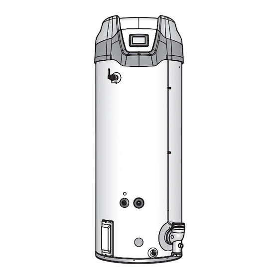
Page 9: Side Views
LEFT SIDE RIGHT SIDE Figure 4 9. Temperature-Pressure Relief Valve discharge pipe - see T&P SIDE VIEWS Valve Discharge Pipe Requirements: on page 15. 1. Cleanout access panel, covers water heater cleanout 10. Lower Temperature Probe, 1 of 2 temperature probes. The opening and ASME plate where applicable. -
Page 10: Rough In Dimensions
INSTALLATION CONSIDERATIONS ROUGH IN DIMENSIONS SUPPLY GAS CONNECTION INTAKE AIR CONNECTION 3 INCH PVC WATER OUTLET HEIGHT T & P VALVE FRONT BACK 3/4” NPT RECIRCULATION RETURN LOWER VENT TEMPERATURE CONNECTION PROBE 3 INCH PVC (exhaust elbow) CLEANOUT 1 1/2” NPT WATER 3/4”... -
Page 11: Locating The Water Heater
GAS LINE CONNECTION SIZE STORAGE CAPACITIES TABLE 1 TABLE 2 † MODEL SERIES NATURAL GAS PROPANE GAS MODEL U. S. GALLONS LITERS SUF 60120 300/301 3/4 "NPT 3/4 "NPT SUF 60120 SUF 100150 300/301 3/4 "NPT 3/4 "NPT SUF 100150 SUF 100199 300/301 3/4 "NPT... -
Page 12: Extended Vent Terminations
There is a risk in using fuel burning appliances such as gas Contact your local distributor or call the parts department phone water heaters in rooms, garages or other areas where gasoline, number listed on the back cover of this manual to order 4 inch other flammable liquids or engine driven equipment or vehicles termination(s). -
Page 13: Installation Requirements
combustion, potentially resulting in fire, asphyxiation, serious • DO NOT cover the instruction manual. Keep it on the side of personal injury or death. the water heater or nearby for future reference. • DO NOT apply insulation to the top of the water heater, as •... -
Page 14: Mixing Valves
MIXING VALVES HOT WATER Water temperature over 125°F (52°C) OUTLET can cause severe burns instantly resulting in severe injury or death. 12” TO 15” (30-38 cm) Children, the elderly and the physically or mentally disabled are at TEMPERED WATER OUTLET highest risk for scald injury. -
Page 15: Temperature-Pressure Relief Valve
TEMPERATURE-PRESSURE RELIEF VALVE water in adequate quantities should circumstances demand. If the discharge pipe is not connected to a drain or other suitable means, the water flow may cause property damage. CAUTION Explosion Hazard Water Damage Hazard Temperature-Pressure Relief Valve must comply with ANSI Z21.22- •... -
Page 16: Condensate Drain
CONDENSATE DRAIN COMBUSTIBLE MATERIAL STORAGE The water heaters covered in this manual are condensing appliances and require a building drain to be located in close proximity to allow the condensate to drain safely. Fire or Explosion Hazard Condensate drains from the water heater at the exhaust elbow located at the bottom. -
Page 17: Air Requirements
AIR REQUIREMENTS UNUSUALLY TIGHT CONSTRUCTION In unconfined spaces in buildings, infiltration may be adequate to provide air for combustion, ventilation and dilution of flue gases. However, in buildings of unusually tight construction (for example, weather stripping, heavily insulated, caulked, vapor barrier, etc.) additional air must be provided using the methods Breathing Hazard - Carbon Monoxide Gas described in the Confined Space section that follows. -
Page 18: Fresh Air Openings For Confined Spaces
FRESH AIR OPENINGS FOR CONFINED SPACES Alternatively a single permanent opening, commencing within 12 inches (300 mm) of the top of the enclosure, shall be provided. The following instructions shall be used to calculate the size, See Figure 10. The water heater shall have clearances of at number and placement of openings providing fresh air for least 1 inch (25 mm) from the sides and back and 6 inches (l50 combustion, ventilation and dilution in confined spaces. -
Page 19: Outdoor Air Through Two Vertical Ducts
OUTDOOR AIR THROUGH TWO VERTICAL DUCTS When ducts are used, they shall be of the same cross sectional area as the free area of the openings to which they connect. The illustrations shown in this section of the manual are a The minimum dimension of rectangular air ducts shall be not less reference for the openings that provide fresh air into confined than 3 inches (7.62 cm). -
Page 20: Installation Requirements - Commonwealth Of Massachusetts
INSTALLATION REQUIREMENTS - COMMONWEALTH OF MASSACHUSETTS COMMONWEALTH OF MASSACHUSETTS INSPECTION The state or local gas inspector of the side wall horizontally For all side wall terminated, horizontally vented power vent, direct vented gas fueled equipment shall not approve the installation vent, and power direct vent gas fueled water heaters installed in unless, upon inspection, the inspector observes carbon every dwelling, building or structure used in whole or in part for... -
Page 21: Venting Installation
VENTING INSTALLATION CATEGORY IV APPLIANCE Category IV appliances operate with a positive vent (exhaust) static pressure and with vent gas temperatures low enough to Breathing Hazard - Carbon Monoxide Gas produce condensate in the vent piping. • POWER VENT CONFIGURATION Install vent system in accordance with codes. -
Page 22: Intake Air Connection
18. Stress levels in pipe/fittings can be significantly increased by when viewed from the end, see Figure 15. The Tee fitting's improper installation. If rigid pipe clamps are used to hold 1/2 inch branch and hose barb must not be angled any lower the pipe in place, or if the pipe cannot move freely through a (towards the ground) than this factory specification. -
Page 23: Common Venting
including joining the pipe to the factory provided terminations (PVC TABLE 6 - PVC/CPVC and Polypropylene material). PVC Materials should use ASTM D-2564 Grade Cement; Number of 3 Inch Pipe 4 Inch Pipe CPVC Materials should use ASTM F-493 Grade Cement and ABS 90°... -
Page 24: Direct Vent Installation
If the vent piping will terminate vertically, through a roof, see If a concentric termination(s) will be used see Concentric Vertical Termination Installation on page 25. Termination Installation on page 30. If the vent piping will terminate horizontally, through a If a low-profile termination will be used see Low Profile sidewall, see Sidewall Termination Installation on page 27. -
Page 25: Intake Air Screen
See Figure 20. A horizontal section of the air inlet pipe, near the heater should include a 3” by 3” by 1/2” tee and a hose barb fitting to drain the water. The tee should be as close to the heater as is practical. The drain tubing in any installation should have a loop trap and flow to an appropriate waste drain. - Page 26 8. Suspend the pipe(s) through center of hole using field IF LESS THAN supplied metal strapping or equivalent support materials as 10 FEET (3 m) shown in Figure 22 on page 26. 9. Slide a roof boot or equivalent flashing over the pipe and secure roof boot or equivalent flashing to roof and seal around the flashing as shown in Figure 22, Figure 23 and 24 INCHES (60 cm)
-
Page 27: Sidewall Termination Installation
SIDEWALL TERMINATION INSTALLATION 18. Cut a 4 inch (10 cm) diameter hole for 3 inch pipe or 5 inch (13 cm) diameter hole for 4 inch pipe where the pipe(s) will 12. Determine the location for the termination(s). pass through the wall. 13. -
Page 28: Polypropylene Installations
POLYPROPYLENE INSTALLATIONS Polypropylene vent systems do not use cement to connect the pipe and elbow sections but use a push together gasket The water heater has been approved to be installed with seal method. Do not attempt to connect Polypropylene with Polypropylene vent material as shown in Tables 7 and 8. -
Page 29: Al29-4C ® Vent Installations
AL29-4C VENT INSTALLATIONS ® Listed vent systems composed of AL29-4C® must not mix parts from the different manufacturers. The joints of these (AL29-4C® is a registered trademark of Allegheny Technologies, Inc.) products are sealed by internal gaskets. Do not use any The water heaters covered by this manual are approved other type of sealant. -
Page 30: Concentric Termination Installation
CONCENTRIC TERMINATION INSTALLATION NOTE: If this required 10 foot (3 m) distance to a parapet, vertical wall or structure cannot be maintained, standard 1. Concentric terminations must be ordered separately. terminations must be used. See Vertical Termination SUF 60120 thru SUF 100250 models must use the 4 inch Installation on page 25. -
Page 31: Inch Concentric Termination Installation
4 INCH CONCENTRIC TERMINATION INSTALLATION the piping to the concentric termination using field supplied 4" x 3" reducer couplings and short sections of 3 inch pipe (18 inches or less) pipe. Do not exceed the maximum INTAKE AIR CONNECTION INTAKE AIR PIPE 3 INCH PVC equivalent vent length listed on page 23. - Page 32 MULTIPLE CONCENTRIC TERMINATION CLEARANCES Four Concentric Terminations When installing multiple concentric terminations vertically through 1. When installing four concentric terminations through a roof or a roof or horizontally through a sidewall ensure the required through a sidewall in close proximity they may be arranged clearances (separation) between terminations are maintained.
-
Page 33: Multiple Concentric Termination Arrangements
MULTIPLE CONCENTRIC TERMINATION ARRANGEMENTS SIDEWALL The illustrations on this page show some of the installation arrangements for multiple concentric terminations that are allowed. See Multiple Concentric Termination Clearances on page 32 for detailed information on clearances and additional arrangement options. NOTE: When multiple concentric terminations are installed through a roof in the same location all termination caps must be at the same height measured from the ground. -
Page 34: Low Profile Vent Installation
LOW PROFILE VENT INSTALLATION To Heater Intake Air Connection This water heater is certified for sidewall direct venting with IPEX System 636 Low Profile Vent Kit. Follow instructions below for From Heater Vent proper installations. Pipe Connection All termination kits must be located and installed in accordance 12”... -
Page 35: Venting Arrangements
VENTING ARRANGEMENTS Enlarged View of Direct Vent Air Intake Moisture Protection Power Vent Vertical Power Vent Horizontal Direct Vent Vertical Figure 42 Figure 43 Figure 44 Enlarged View of Direct Vent Air Intake Moisture Protection Enlarged View of Direct Vent Air Intake Enlarged View of Moisture Protection Direct Vent Air Intake... - Page 36 VENTING ARRANGEMENTS Enlarged View of Direct Vent Air Intake Moisture Protection Enlarged View of Enlarged View of Direct Vent Air Intake Direct Vent Air Intake Moisture Protection Moisture Protection Direct Vent Vertical Concentric Direct Vent Horizontal Concentric Direct Vent Horizontal Low Profile Figure 48 Figure 49 Figure 50...
-
Page 37: Termination Clearances Sidewall Power Vent
TERMINATION CLEARANCES SIDEWALL POWER VENT POWER VENT (using room air for combustion) EXTERIOR CLEARANCES FOR SIDEWALL VENT TERMINATION Figure 51 Vent terminal clearances for “Power Vent” installations. Power Vent configurations use room air for combustion. CANADIAN INSTALLATIONS US INSTALLATIONS CANADIAN INSTALLATIONS US INSTALLATIONS Clearance to each side Clearance in accordance... -
Page 38: Termination Clearances Sidewall Direct Vent
TERMINATION CLEARANCES SIDEWALL DIRECT VENT DIRECT VENT (using outdoor air for combustion) EXTERIOR CLEARANCES FOR SIDEWALL VENT TERMINATION Figure 52 Vent terminal clearances for “Direct Vent” installations. Direct Vent configurations use outdoor air for combustion. CANADIAN INSTALLATIONS US INSTALLATIONS CANADIAN INSTALLATIONS US INSTALLATIONS Clearance to each side Clearance in accordance... -
Page 39: Water Heater Installation
WATER HEATER INSTALLATION CONDENSATE DRAIN INSTALLATION INSTALLATION INSTRUCTIONS 1. Ensure the water heater’s Enable/Disable switch is in the Installation must conform with these instructions and local “Disable” position. building codes. 2. Install a 1/2 inch PVC condensate drain line between Field supplied materials required for installation include: condensate drain connection on the Exhaust/Condensate Elbow •... -
Page 40: Supply Gas Line Installation
SUPPLY GAS LINE INSTALLATION GAS LINE SIZING Depending on the developed equivalent length and/or the number Contact your local gas utility company to ensure that adequate of appliances connected to a common main, the size of supply gas gas service is available and to review applicable installation lines may have to be increased. -
Page 41: Gas Line Leak Testing
GAS LINE LEAK TESTING GAS LINE CONNECTION 1. The water heaters covered by this manual are shipped from the factory with 3/4 inch supply gas connections. The supply gas line must not be smaller than 3/4 inch. Connect the supply gas line to the water heater's 24 Volt Gas Valve in accordance Fire and Explosion Hazard with all applicable local and national code requirements. -
Page 42: Power Supply Connections
POWER SUPPLY CONNECTIONS heating operation during periods when the building is unoccupied or there is no demand for hot water. Read the requirements for the Power Supply on page 13 before connecting power. To use the enable/disable circuit it must first be activated by selecting the “Use External Enable”... -
Page 43: Water Line Connections
WATER LINE CONNECTIONS T&P VALVE DISCHARGE PIPE The water piping installation must conform to these instructions and to all local and national code authority having jurisdiction. Good practice requires that all heavy piping be supported. Read and observe all requirements in the following sections Explosion Hazard before installation of the water piping begins: 1. -
Page 44: Temperature Regulation
TEMPERATURE REGULATION HIGH TEMPERATURE LIMIT CONTROL (ECO) TABLE 13 Time for Permanent Burns This water heater is equipped with an ECO (energy cut out) non Water Temperature Time for 1st Degree Burn 2nd & 3rd Degree °F (°C) (Less Severe Burns) adjustable high temperature limit switch. -
Page 45: Control System Operation
CONTROL SYSTEM OPERATION OVERVIEW THE DESKTOP SCREEN During normal operation the control system will display the The water heaters covered in this manual are equipped with an "Desktop" screen on the LCD Touch Display which is the default electronic control system that regulates water temperature inside the screen. -
Page 46: Status Icons
STATUS ICONS The Status Icons are displayed on the Desktop screen and convey operational and diagnostic information. The icons are described in the table below. See Figure 59 on page 45. Ensure the water heater is properly grounded. Flame sensing requires an adequate earth ground. -
Page 47: Operating States
OPERATING STATES The current operational state of the water heater is displayed on the Desktop screen as the "Status." The common operational states are described in the table below. See Figure 59 on page 45. Ensure the water heater is properly grounded. Flame sensing requires an adequate earth ground. -
Page 48: User Settings & Control System Menus
USER SETTINGS & CONTROL SYSTEM MENUS TEMPERATURES MENU Operating Set Point And Differential Adjustment The Operating Set Point is adjustable from 90°F (42°C) to 180°F (82°C). The factory setting is 120°F (49°C). The Differential is adjustable from 2° to 20°. The factory setting is 8°. These user settings are accessed from the Temperatures menu. The following instructions will explain how to adjust these settings and navigate the control system menus. - Page 49 TEMPERATURES MENU (CONT) DESCRIPTION/ACTION DISPLAY • Differential - Adjustable user setting that changes the tank temperature differential with a range of 2° to 20°F. The factory Temperatures setting is 8°F. Operating Setpoint 120°F > • Tank Temperature - Non adjustable. Control system sensed temperature (averaged from upper &...
-
Page 50: Display Settings
DISPLAY SETTINGS DESCRIPTION/ACTION DISPLAY Press Display Settings from the Main Menu to enter this menu. Display Settings This menu contains adjustable display options for viewing Temperature Units °F > information on the UIM’s LCD screen. Use the Slidebar to navigate the menu. Brightness 5 >... - Page 51 CURRENT FAULT DESCRIPTION/ACTION DISPLAY Press Current Fault from the Main Menu to enter this menu. This menu contains non adjustable operational information. Use the Blocked Exhaust Slidebar to navigate the menu. 0 days 0 hr 0 min ago This menu contains the current Fault or Alert error message. The Error Code: A8-1201 time the Fault or Alert message occurred appears directly below.
-
Page 52: Service Contact Information
SERVICE CONTACT INFORMATION The control system has a discrete menu that Installing contractors and/or service agents can access to enter contact information for their customers. This contact information will be displayed with all Fault and Alert messages. DESCRIPTION/ACTION DISPLAY From the Desktop Screen (see Figure 59 on page 45) press Contact Information and hold down the middle (unmarked) area located between Show Contact... -
Page 53: Prior To Start Up
START UP PRIOR TO START UP On the water heaters covered by this manual there are test ports for supply and manifold gas pressure readings Installation and start up of this water heater requires abilities on the gas valve. Using a small flat tip pocket screw driver and skills equivalent to that of a licensed tradesman in the field - open the needle valve inside the supply gas pressure involved, see Qualifications on page 6. -
Page 54: Lighting The Water Heater
LIGHTING THE WATER HEATER LIGHTING & OPERATION LABELS The instruction label below is affixed to the water heater's covered by this manual at the factory and must be followed when lighting and operating the water heater. FOR YOUR SAFETY READ BEFORE LIGHTING WARNING: If you do not follow these instructions exactly, a fire or explosion may result causing property damage, personal injury... - Page 55 SUPPLY GAS PRESSURE ADJUSTMENT Multiple Water Heater Installations: In multiple water heater installations or in installations where the installed water heater(s) share a common gas supply main with other gas fired appliances; the supply gas pressures shall Fire and Explosion Hazard be measured at each water heater with all gas fired appliances connected to a common main firing at full capacity.
-
Page 56: Checking The Firing Rate
CHECKING THE FIRING RATE HIGH ALTITUDE INSTALLATIONS If firing rate adjustment is required follow these instructions to determine the actual firing rate of the water heater: NOTE: The heaters covered by this manual are capable of Fire and Explosion Hazard modulating their firing rate. -
Page 57: Troubleshooting
TROUBLESHOOTING SEQUENCE OF OPERATION INSTALLATION CHECKLIST Read the Sequence of Operation below before attempting to The list below represents some of the most critical correct any operational problems. Refer to the Features And installation requirements that, when overlooked, often result Components section beginning on page 7 for the location in operational problems, down time and needless parts of various water heater components described below. -
Page 58: Sequence Of Operation Flow Chart
SEQUENCE OF OPERATION FLOW CHART Sequence is shown with Enable/Disable Switch in the Enable position If tank temperature drops below Operating Set Point minus Differential setting a heating cycle is activated Control System performs diagnostic checks Control System Locks Out Normal State of all pressure switches and ECO are checked Displays Fault Msg Pressure switches and ECO are verified closed... -
Page 59: Operational Problems
OPERATIONAL PROBLEMS • Vent (exhaust) gas recirculation at the vent and intake air pipe terminations on Direct Vent installations - see Direct Vent Installation on page 24. • Excessive equivalent lengths of intake air and/or vent (exhaust) piping installed - see Venting Requirements on Read and understand this instruction page 22. -
Page 60: Fault And Alert Conditions
• Sediment or lime scale accumulation may be affecting mark. The water heater will continue to operate during an Alert water heater operation. See Maintenance on page 63 for condition but the water heater must be serviced by a qualified sediment and lime scale removal procedures. - Page 61 FAULT AND ALERT MESSAGES Call the technical support phone number listed on the back cover for further technical assistance or to locate a qualified service agent in your area. POSSIBLE CAUSES - CHECK/REPAIR DISPLAYED FAULT/ALERT MESSAGE • Using a manometer, ensure that gas supply pressure is above Ignition Failure minimum requirement listed on heater’s data plate and does not 0 days 0 hrs 0 mins ago...
- Page 62 FAULT AND ALERT MESSAGES (CONT) Call the technical support phone number listed on the back cover for further technical assistance or to locate a qualified service agent in your area. POSSIBLE CAUSES - CHECK/REPAIR DISPLAYED FAULT/ALERT MESSAGE • If Blocked Intake error occurs before blower runs, make sure Blocked Air Intake pressure switch connections are clean and tight.
-
Page 63: Maintenance
MAINTENANCE GENERAL MAINTENANCE SCHEDULE TABLE 17 Keep water heater area clear and free from combustible COMPONENT OPERATION INTERVAL REQUIRED materials, gasoline, and other flammable vapors and liquids. See Tank Sediment Removal Semi Annually Flushing Locating The Water Heater on page 11. Lime Scale Tank Semi Annually... -
Page 64: Filling The Water Heater
5. Ensure the drain hose is secured before and during the entire flushing procedure. Flushing is performed with system water CLEANOUT pressure applied to the water heater. TANK ACCESS PANEL 6. Open the water heater drain valve to flush the storage tank. CLEANOUT CLEANOUT OPENING... -
Page 65: Powered Anode Rods
TABLE 18 TEMPERATURE-PRESSURE UN-LIME® PROFESSIONAL DELIMER RELIEF VALVE Part Number Description 9005416105 4 - 1 gallon (case) 9005417105 1 - 5 gallon POWERED ANODE RODS DISCHARGE PIPE To insure a long, trouble-free operating life, the water heaters covered in this manual are factory equipped with a powered Figure 65 anode system. -
Page 66: Diagrams
DIAGRAMS CCB - CENTRAL CONTROL BOARD LAYOUT Figure 66... -
Page 67: Wiring Diagram
WIRING DIAGRAM Figure 67... -
Page 68: Circulation Pump Wiring Diagrams
CIRCULATION PUMP WIRING DIAGRAMS CIRCULATING PUMP WIRING DIAGRAM STORAGE TANK OR BUILDING RECIRCULATION FIELD SUPPLIED TEMPERATURE CONTROL INSTALLED IN THE STORAGE TANK OR CIRCULATING LOOP RETURN LINE NOTE: USE SEPARATE 120 VAC POWER SUPPLY FOR PUMP CIRCUIT. DO NOT SHARE POWER WITH WATER HEATER AS THIS MAY CAUSE ELECTRICAL LINE NOISE AND LEAD TO ERRATIC CONTROL SYSTEM OPERATION. -
Page 76: Notes
NOTES... - Page 77 NOTES...
- Page 78 NOTES...
-
Page 79: Warranty
For your records, fill in the product: Serial: ___________________ Model: ___________________ U.S. Customers: State Water Heaters 500 Tennessee Waltz Parkway Ashland City, Tennessee 37015 800-365-0024 www.statewaterheaters.com... - Page 80 500 Tennessee Waltz Parkway, Ashland City, TN 37015 Tech Support: 800-365-0024 Parts: 800-821-2017 www.statewaterheaters.com Copyright © 2017 State Water Heaters, All rights reserved.
Need help?
Do you have a question about the SUF-100-199NE and is the answer not in the manual?
Questions and answers
Do you have a question about the SUF-100-199NE and is the answer not in the manual? Could you send me a manual for this hot water heater. Someone has misplaced the manual that came with it. Would be most appreciative in you could copy of manual to: Dsmith1942216@outlook.com; The water heater is for Church baptistry and we had to boil water early in the morning to get a water temperatre that we could use for baptisms. Sincerely, Douglas Smith